EP0906529B1 - Aiguille de commande - Google Patents
Aiguille de commande Download PDFInfo
- Publication number
- EP0906529B1 EP0906529B1 EP19970921647 EP97921647A EP0906529B1 EP 0906529 B1 EP0906529 B1 EP 0906529B1 EP 19970921647 EP19970921647 EP 19970921647 EP 97921647 A EP97921647 A EP 97921647A EP 0906529 B1 EP0906529 B1 EP 0906529B1
- Authority
- EP
- European Patent Office
- Prior art keywords
- valve
- piston
- drilling
- activating pin
- channel
- Prior art date
- Legal status (The legal status is an assumption and is not a legal conclusion. Google has not performed a legal analysis and makes no representation as to the accuracy of the status listed.)
- Expired - Lifetime
Links
- 230000004913 activation Effects 0.000 title 1
- 230000003213 activating effect Effects 0.000 claims description 103
- 238000005553 drilling Methods 0.000 claims description 81
- 238000007789 sealing Methods 0.000 claims description 39
- 230000008878 coupling Effects 0.000 claims description 15
- 238000010168 coupling process Methods 0.000 claims description 15
- 238000005859 coupling reaction Methods 0.000 claims description 15
- 239000007788 liquid Substances 0.000 claims description 5
- 230000002401 inhibitory effect Effects 0.000 claims description 2
- 230000000670 limiting effect Effects 0.000 claims description 2
- 230000007704 transition Effects 0.000 claims 4
- 238000005086 pumping Methods 0.000 description 11
- 230000000694 effects Effects 0.000 description 2
- 230000006872 improvement Effects 0.000 description 2
- 238000013178 mathematical model Methods 0.000 description 2
- 238000003801 milling Methods 0.000 description 2
- 230000000903 blocking effect Effects 0.000 description 1
- 230000008859 change Effects 0.000 description 1
- 238000010276 construction Methods 0.000 description 1
- 239000013013 elastic material Substances 0.000 description 1
- 230000002349 favourable effect Effects 0.000 description 1
- 230000003993 interaction Effects 0.000 description 1
- 230000014759 maintenance of location Effects 0.000 description 1
- 239000000463 material Substances 0.000 description 1
- 238000000034 method Methods 0.000 description 1
- 238000012986 modification Methods 0.000 description 1
- 230000004048 modification Effects 0.000 description 1
- 230000009467 reduction Effects 0.000 description 1
- 230000002829 reductive effect Effects 0.000 description 1
- 230000000284 resting effect Effects 0.000 description 1
- 239000000725 suspension Substances 0.000 description 1
Images





Classifications
-
- B—PERFORMING OPERATIONS; TRANSPORTING
- B60—VEHICLES IN GENERAL
- B60S—SERVICING, CLEANING, REPAIRING, SUPPORTING, LIFTING, OR MANOEUVRING OF VEHICLES, NOT OTHERWISE PROVIDED FOR
- B60S5/00—Servicing, maintaining, repairing, or refitting of vehicles
- B60S5/04—Supplying air for tyre inflation
-
- F—MECHANICAL ENGINEERING; LIGHTING; HEATING; WEAPONS; BLASTING
- F16—ENGINEERING ELEMENTS AND UNITS; GENERAL MEASURES FOR PRODUCING AND MAINTAINING EFFECTIVE FUNCTIONING OF MACHINES OR INSTALLATIONS; THERMAL INSULATION IN GENERAL
- F16K—VALVES; TAPS; COCKS; ACTUATING-FLOATS; DEVICES FOR VENTING OR AERATING
- F16K15/00—Check valves
- F16K15/20—Check valves specially designed for inflatable bodies, e.g. tyres
-
- F—MECHANICAL ENGINEERING; LIGHTING; HEATING; WEAPONS; BLASTING
- F16—ENGINEERING ELEMENTS AND UNITS; GENERAL MEASURES FOR PRODUCING AND MAINTAINING EFFECTIVE FUNCTIONING OF MACHINES OR INSTALLATIONS; THERMAL INSULATION IN GENERAL
- F16L—PIPES; JOINTS OR FITTINGS FOR PIPES; SUPPORTS FOR PIPES, CABLES OR PROTECTIVE TUBING; MEANS FOR THERMAL INSULATION IN GENERAL
- F16L37/00—Couplings of the quick-acting type
- F16L37/08—Couplings of the quick-acting type in which the connection between abutting or axially overlapping ends is maintained by locking members
- F16L37/12—Couplings of the quick-acting type in which the connection between abutting or axially overlapping ends is maintained by locking members using hooks, pawls, or other movable or insertable locking members
- F16L37/20—Joints tightened by toggle-action levers
-
- Y—GENERAL TAGGING OF NEW TECHNOLOGICAL DEVELOPMENTS; GENERAL TAGGING OF CROSS-SECTIONAL TECHNOLOGIES SPANNING OVER SEVERAL SECTIONS OF THE IPC; TECHNICAL SUBJECTS COVERED BY FORMER USPC CROSS-REFERENCE ART COLLECTIONS [XRACs] AND DIGESTS
- Y10—TECHNICAL SUBJECTS COVERED BY FORMER USPC
- Y10T—TECHNICAL SUBJECTS COVERED BY FORMER US CLASSIFICATION
- Y10T137/00—Fluid handling
- Y10T137/3584—Inflatable article [e.g., tire filling chuck and/or stem]
-
- Y—GENERAL TAGGING OF NEW TECHNOLOGICAL DEVELOPMENTS; GENERAL TAGGING OF CROSS-SECTIONAL TECHNOLOGIES SPANNING OVER SEVERAL SECTIONS OF THE IPC; TECHNICAL SUBJECTS COVERED BY FORMER USPC CROSS-REFERENCE ART COLLECTIONS [XRACs] AND DIGESTS
- Y10—TECHNICAL SUBJECTS COVERED BY FORMER USPC
- Y10T—TECHNICAL SUBJECTS COVERED BY FORMER US CLASSIFICATION
- Y10T137/00—Fluid handling
- Y10T137/3584—Inflatable article [e.g., tire filling chuck and/or stem]
- Y10T137/36—With pressure-responsive pressure-control means
-
- Y—GENERAL TAGGING OF NEW TECHNOLOGICAL DEVELOPMENTS; GENERAL TAGGING OF CROSS-SECTIONAL TECHNOLOGIES SPANNING OVER SEVERAL SECTIONS OF THE IPC; TECHNICAL SUBJECTS COVERED BY FORMER USPC CROSS-REFERENCE ART COLLECTIONS [XRACs] AND DIGESTS
- Y10—TECHNICAL SUBJECTS COVERED BY FORMER USPC
- Y10T—TECHNICAL SUBJECTS COVERED BY FORMER US CLASSIFICATION
- Y10T137/00—Fluid handling
- Y10T137/8593—Systems
- Y10T137/87917—Flow path with serial valves and/or closures
- Y10T137/88054—Direct response normally closed valve limits direction of flow
Definitions
- the invention concerns an activating pin for a valve connector for connecting to inflation valves, the connector comprising a housing to be connected to a pressure source, within the housing a coupling hole having a central axis and an inner diameter approximately corresponding to the outer diameter of the inflation valve to which the valve connector is to be connected, and a cylinder and means for conducting gaseous media between the cylinder and the pressure source, and which activating pin is arranged for engaging with a central spring-force operated valve lever of the inflation valve, is arranged to be situated within the housing in continuation of the coupling hole coaxially with the central axis thereof and comprises a piston part with a piston, which piston is to be positioned in the cylinder movably between a first piston position and a second piston position, said activating pin further comprising a valve part.
- Such an activating pin according to preamble of claim 1 is known from WO-A-96/10903.
- an activating pin located within the coupling house can be designed as a piston equipped with a suitable seal and a piston rod that is slidable in the cylinder-shaped coupling house.
- the piston can be held in a longitudinal position against the cylinder valve without applying physical force so that the piston automatically slides, after the valve connector is placed on the inflation valve, by means of compressed air.
- This compressed air comes from the pressure source such that the piston, in the proximal position to the valve, (1) opens up the inner valve, (2) opens the air passage to the valve and, (3) tightens less than 100% against the cylinder wall while in the distal position from the valve.
- Figure 14 in PCT/DK96/00055 shows a valve (360) which must be closed against the piston control.
- the disadvantage is that the above-mentioned two seals must be operational at a certain section of the sliding. This requires very accurate calibration of the cylinder wall and the piston movement.
- the piston has a precisely defined opening zone and can thus only adjust itself to a minor extent to the tolerances of the pump valve in question.
- Figures 8, 9, 10, 14, and 15 in PCT/DK96/00055 show various activating pins equipped with a center blind drilling or a center drilling, side drillings and a V-shaped milling at the bottom which is perpendicular to the center axial drilling of the piston. The effect of this is that more force than necessary has to be applied when pumping, especially at high air velocities.
- Figure 9 in PCT/DK96/00055 shows an activating pin which has a center drilling, side drillings and a V-shaped milling at the bottom.
- the coupling is connected to e.g. a high pressure pump with a built-in check valve
- the spring keeps the valve of the activating pin in a closed position after uncoupling of a Schrader valve. If a tire with a Sclaverand valve has to be pumped immediately afterwards, one has to apply a large force to slide the activating pin which opens the inner valve of the Sclaverand valve. Air will escape and consequently the pumping time will be substantially longer if the tire has already been partly pumped.
- This last-mentioned problem also exists in the embodiments shown in Figures 10 and 15 in PCT/DK96/00055.
- the purpose of the present invention is to produce a reliable activating pin which is: (1) inexpensive, (2) has low aerodynamic drag making it comfortable to use for pumping purposes, and (3) provides the shortest possible pumping time.
- the activating pin further comprises a valve part
- the piston part comprises within it a channel
- the cross-section of said channel is, at at least one part of said piston part, flower-shaped, consisting of essentially identical sectors, wherein in each sector the distance between the center point of the channel cross-section and the outermost limiting surface of the channel is larger than the corresponding distance measured along the line separating the sector from and adjacent sector
- said valve part is positioned movably with respect to said piston part between a first valve position and a second valve position for enabling the conduction of gaseous and/or liquid media through said channel when said valve part is in said first valve position, and inhibiting the conduction of gaseous and/or liquid media through said channel when said valve part is in said second valve position.
- the channels are positioned in a mainly longitudinal direction in relation to the center axis of the housing and can be defined by at least one cross section which approximately can be defined by at least one curve.
- the curve is closed and can be defined by two unique modular parametrisation Fourier Series expansions, one for each co-ordinate function: where 0 ⁇ x ⁇ 2 ⁇ , x ⁇ p ⁇ 0, p ⁇
- the cross section area of the channels is optimized by a certain given cross section: e.g. a section which combines approximately laminar flow and which can guide a central piston valve rod. It is then also possible to obtain a contact area for a Schrader valve core. This means that a bridge is unnecessary.
- curves defined by the formula have been given the name "flower-shaped". The formula is: where 0 ⁇ x ⁇ 2 ⁇ , x ⁇ p ⁇ 0, p ⁇
- an activating pin ensures a large flow cross section which, by means of radial fins, also produces an approximately laminar flow which contributes to a reduced pressure drop during the flow.
- the radial fins can control any centrally positioned valve without blocking the air passage.
- the piston rod is equipped with two blind drillings parallel to the center axis that reaches the activating pin at both ends of the activating pin.
- the piston rod is also equipped with a concentric valve made of an elastic material, e.g. a valve rubber used on a Dunlop-Woods valve and squeezed onto the piston rod between e.g. its upper and lower part covering the radial drilling proximal to the pressure source.
- the radial drilling has an azimuth angle ⁇ larger than or equal to 90° to the center axis of the piston, seen in the flow direction of the air at flow from the side of the pressure source.
- the distal radial drilling has an azimuth angle ⁇ larger than or equal to 90° to the distal center drilling of the piston, seen in the flow direction of the air at flow from the side of the pressure source.
- the radius r 0 in the distal blind drilling is smaller than the radius r 0 of the proximal part of the center drilling. Due to evident arrangements in dimensioning the by-pass, the piston control is proximally equipped with longitudinal air ducts and/or having a bigger diameter.
- the side of the piston is chamfered. If connected to e.g.
- the connector needs to have an airing valve or a similar solution for providing the shortest pumping time. This results in a reliable activating pin because the pin valve works independently of the piston control fit and tolerances of the pump valves in question. It also results in a pin with low aerodynamic drag, which is comfortable for pumping purposes and which is inexpensive to produce.
- a second embodiment is an improvement of the first embodiment where the coupling is connected to e.g. a high-pressure pump with a built-in non-return valve.
- a spring force being produced by means of the combination of compressed air and the valve lever passing through the piston in an eccentric position ensures the lowest possible pumping time.
- the effect of the eccentric valve lever is that the air pressure in the space between the non-return valve of the pump and the activating pin becomes equal to the pressure of the surroundings as the valve lever opens the above-mentioned space if a Schrader valve is disconnected. It is thus always possible to couple a Sclaverand valve without air escaping from the tire.
- an airing valve which is constantly shut could be established in the above-mentioned space when the connector is coupled to the valves or when the activating pin touches the core of the Schrader valve. This can take place if, for example, the airing is shaped as a narrow channel at the pressurized side of the activating pin relative to the distal end of it.
- the eccentric valve lever is integrated in the piston valve which makes the activating pin inexpensive to produce. The pin works independently of the piston control fit.
- a third embodiment comprises a similar combination to the one described in the second embodiment, except here the pin has a center drilling. It is appropriate if the center drilling at each end expands gradually by a circular cross section and has an angle ⁇ or ⁇ , respectively, with the center axis of the activating pin and each angle is larger than 0° and smaller than 20° (usually in the interval between 6° and 12°).
- the top of the piston of the activating pin forms a valve seat for the valve (304). This results in a large opening area created by a small movement of the eccentric valve lever.
- the eccentric valve lever is loose in the piston and a stop device is used to stop its movement.
- the stop device is an integrated part of the piston valve and is resilient in relation to it.
- the piston valve rod has e.g. a "flower-shaped" cross section and the piston rod e.g. a circular cross section, resulting in channels (321).
- the activating pin is very reliable and inexpensive to produce.
- the air flow in the valve connector is approximately laminar which ensures low aerodynamic drag so that it is comfortable when pumping even with (low pressure) pumps without an integrated non-return valve.
- the improvement over the activating pin shown in figure 9 in PCT/DK96/00055 is considerable regarding reduction in pumping force and pumping time and is as good as e.g. the valve connector of figures 5A, 5B, 6 and 7.
- a fourth embodiment is an alternative to the third embodiment.
- the cross section of the piston rod can have two main forms, according the specific formula each being "flower-shaped" with different parameters, both resulting in an approximately laminar flow.
- the radius r 0 is smaller than the radius of the core of a Schrader valve while the air is flowing through the distals of the "flower shaped" cross section.
- the eccentric valve lever is similar to the loose type of Figure 5D, with the difference being that the top is rounded off. The characteristics of this model are almost in accordance with those of the third embodiment.
- the activating pin is designed as a piston with a piston rod that is slidable in the cylinder-shaped coupling house.
- the activating pin has a center drilling with an axially slidable valve in the center drilling that is kept closed by a spring where the center drilling of the activating pin has e.g. a "flower-shaped" cross section (D-D, figure 8B) and the piston valve rod has a circular one resulting in a reliable control and efficient air passage.
- the center drilling at each end expands gradually by a circular cross section.
- the walls of the gradual expansions form an angle ⁇ or ⁇ , respectively, between 0° and 20° (usually in the interval between 6° and 12°).
- the wall of the gradual expansion by the piston part of the center drilling forms a valve seat for the seal face of the valve.
- the seal face of the valve is pressed into the correct position by a spring, e.g. an elastic band.
- the sealing surface is a small area with an angle ⁇ , in relation to the center axis, of approximately 90°-154° (incl.) as seen in the flow direction of the air at flow from the side of the pressure source. This enables improved sealing.
- the valve is equipped with at least one fin or a similar device, which fits on the top of the edge of a Dunlop-Woods inner valve.
- the fin is equipped with a device perpendicular to the fin.
- the center drilling in the last-mentioned embodiment can also be designed in a way that provides a favorable flow in the area around the fin of the piston part. If e.g. combined with a pump with a built-in check-valve, the space between the connector and the check-valve need to have an airing or a similar solution.
- the activating pin is reliable, as it works independent of the piston rod fit and the tolerances of the pump valves. It is inexpensive to produce and it gives a low pump force, specifically with pumps without a check-valve. It works independent of piston control fit or pump valve tolerances.
- the activating pin has a center axial drilling with a valve that is axially slidable in the drilling and is kept closed by means of a spring.
- the valve and the spring are made of one piece of deformable material.
- the axially slidable valve and the spring are partly formed by a conic section, with an apex angle (2 ⁇ ), and partly formed by an approximately cylindrical section with a mainly circular cross section.
- the spring is attached to the piston part of the activating pin by means of a securing device. This is expedient if the wall of the center drilling in the activating pin is gradually expanded and has an angle ⁇ or ⁇ , respectively, in relation to the center axis of the activating pin.
- each angle is larger than 0° and smaller than 20° (usually in the interval between 6° and 12°).
- the wall of the gradual expansion of the center drilling thus forms a valve seat for the seal face of the valve.
- the valve is pulled to the tightening position by the spring.
- the piston part is equipped with at least one fin or a similar device which fits on top of the core of a Schrader valve.
- the slidable valve has two cones resting upon each other. This turns the air flow around the valve and in the grooves into an approximately laminar flow.
- the piston valve rod and the piston rod define e.g. a cylindrical channel, while the rest of the piston rod has a "flower-shaped" cross section.
- the embodiment of the flow ensures low aerodynamic drag so that it is comfortable when pumping even with low pressure pumps without an integrated non-return valve.
- the invention is inexpensive. It works independently of piston control fit and pump valve tolerances.
- the sealing surface of the cones is a small area with an angle ⁇ in relation to the center axis of approximately 90°-150° (incl.) with the center axis as seen in the flow direction of the air at flow from the side of the pressure source.
- This enables improved sealing.
- the space between the connector and the check-valve needs to be equipped with airing or the like. Instead of air, (mixes of) gasses and/or liquids of any kind can activate and flow through and around the embodiments of the activating pin.
- the invention can be used in all types of valve connectors, where at least a Schrader valve or any valve with a spring operated core can be coupled, irrespective of the method of coupling or the amount of coupling holes in the connector. Further, the invention can be coupled to any pressure source irrespective of whether or not there is a securing means in the valve connector. Any possible combination of the embodiments shown in the specification fall into the scope of the present invention.
- the various embodiments described above are provided by way of illustration and should not be constructed to limit the invention. Those skilled in the art will readily recognize various modifications and changes which may be made to the present invention without strictly following the exemplary embodiments and applications illustrated and described herein, and without departing from the true spirit and scope of the present invention.
- Figure 1A shows a cross section of e.g. a piston rod 801 with a channel 802. Its curve is defined by two unique modular parametrisation Fourier Series expansion.
- Figure 1B shows a mathematical model of the "flower-shaped" cross section that provides a suitable approximation.
- the change from a center drilling 303,410,533,653 to the circle section of expansions 312,313,411,412,538,539,658 can mathematically be expressed by r 0 ⁇ r max under retention of the other parameters.
- Figure 2B shows the radial drilling 127 which is open at an angle ⁇ to the blind drilling 128.
- the angle ⁇ is shown larger than 90°.
- the radial drilling 127 leads to e.g. a center blind drilling 128 at a distal position on the piston rod 122.
- FIG 3A shows a further development of the activating pin shown in Figure 2.
- the axially movable piston valve 225 is shown in an activated position by operation of the eccentric valve lever 226 which is integrated in the piston valve 225.
- the piston valve rod 227 has a sealing surface 228 which is positioned at the end. This ensures that the piston valve 225 always opens up to make air flow possible, e.g. from the space between the non-return valve of a pump and the activating pin to the surroundings, when a Schrader valve is uncoupled.
- the piston rod 223 has a sealing 229 with a sealing surface 230.
- the piston valve 225 has a sealing 238 with sealing surface 239 and the top of the piston 222 has a sealing surface 240.
- the radius r 0 of drilling 248 is smaller than radius r 0 of drilling 224.
- the air flows through the center drilling 224, which has a "flower-shaped" section, and around the piston rod 227 which has a circular cross section resulting in channels 234 (section A-A) which form the center drilling 224.
- a stop device 231 prevents the piston valve from being pulled out of the activating pin as it strokes against the piston rod 223.
- a radial drilling 247 is positioned distally.
- the center axis 237 of the activating pin is also shown.
- the piston valve can have a gradual expansion (not shown) proximal to the pressure source.
- Figure 3B shows the activating pin according to Figure 3A where the piston valve 225 is kept shut by air pressure.
- the valve function is fulfilled by the sealing 236 in full accordance with Figure 2.
- the stop device 231 has a stop surface 232 and the piston rod 223 has a stop surface 233.
- Channel 241 which has a cross section similar to channel 323 or 545.
- Figure 3C shows section A-A of the piston valve 223, which has a "flower-shaped" section, and the piston valve rod 227 which has a circular cross section resulting in air channel 234 in order to enable a suitable flow through the section with reliable guidance of the piston valve rod 227.
- Figure 3D shows view X of the top of the activating pin where the piston valve rod 227 is hung in the shackle 235.
- the figure also shows the eccentric valve lever 226 which is integrated into the piston valve 225 and which is a section of a cylinder surface.
- the valve lever is made by means of at least two legs that can be arranged rotationally symmetric around the center axis 237 of the activating pin.
- Channel 242 is located between the shackle 235, the piston valve 225.
- Figure 4 shows the third embodiment of the activating pin with the piston 301 in its distal position relative to the pressure source in a coupling house of a valve connector that can be squeezed onto tire valves.
- the piston 301 has a piston rod 302 and a center drilling 303.
- the activating pin has a piston valve 304 and an eccentric valve lever 305. Also shown are the center axis 337 and piston ring 338.
- the "flower-shaped" cross-section of the piston valve rod 322 defines air channels 321 which e.g. four can be used in order to get an approximately laminar air flow.
- the stop 315 prevents the piston valve 304 from being pulled out of the activating pin in cases where the coupling is connected to a piston pump without a non-return valve.
- the stop 315 is resiliently mounted by means of the bar 316 in the bottom 317 of the piston valve rod 322.
- the cross section of this channel changes constantly over its length.
- the activating pin has distally at least one fin or a shackle 318 which is optimally shaped in terms of air flow.
- Channel 324 is defined by partly the inside and outside (see section B-B) of the piston rod 302, and partly by bar 316.
- Channel 325 is defined by piston rod 304, sealing 306 and the eccentric valve lever 305.
- Figure 5B shows the activating pin according to Figure 5A where the piston valve 304 is kept shut by air pressure.
- the stop device 315 has a stop surface 319 and the stop surface 320 is a part of the piston rod 302.
- Figure 5C shows a section B-B with the air channel 311 which has a suitable flow through the section area. Moreover, the stop device 315 and the fin 318 are shown.
- Figure 5D shows the activating pin in an activated position with an eccentric valve lever 350 which is freely movable in the piston 301 of the activating pin and on which the piston valve 353 presses at the top 351.
- the stop device 352 ensures that the valve lever does not fall through the piston 301.
- the valve lever has at least two legs which can be positioned rotationally and symmetrically around the center axis 337 of the activating pin.
- the valve lever can also be designed as the valve lever 226 shown in Figure 3A. Embodiments described in Figure 5D are, of course, also applicable in connection with the other embodiments.
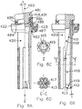
- Figure 6A shows a fourth embodiment of the activating pin, which is similar to the third embodiment, in a position where the piston valve 401 is opened by the activated eccentric valve lever 402.
- the piston valve 401 rotates over an angle ⁇ from the center axis 403 of the activating pin.
- the piston valve 401 rotates around an axis 404 which is perpendicular to the center axis 403.
- the rotation of the piston valve 401 is limited by the stop device 405.
- the piston valve 401 has a sealing 414 with a sealing surface 406, while the piston 407 has a sealing surface 408.
- the rest of the activating pin is similar to Figure 5A, except for the piston rod 420 and the eccentric valve lever 402 which has a rounded top 421 as shown in Fig. 5D.
- the channel 422 is defined by the piston valve 401, the sealing 414, the piston 407 and the eccentric valve lever 402.
- the channel 423 is defined by the piston 407 and the piston valve 401.
- Figure 6B shows the activating pin similar to fig. 6A with the piston valve 401 shut.
- the piston rod 409 has different parameters for the "flower-shaped" cross section of the center drilling 418. Also here are two gradual expansions 410,419 and walls 411,412, respectively, with characteristics according to those of Figure 5A: angles ⁇ and ⁇ in relation to the center axis 403.
- the contact area 413 (see also Fig. 6B) of the activating pin with a Schrader valve has a cone shape. No bridge is necessary, as r 0 is smaller than the diameter of the core of a Schrader valve.
- Figure 6C shows view Z of Fig. 6A with fin 415 and opening 416.
- Figure 6D shows cross section C-C of Figure 6B with the "flower-shaped" cross section of the piston rod 409 defining air channel 417. Also shown is a contact area 413 for engaging with the core of a Schrader valve.
- Figure 7 shows a fifth embodiment with the piston 531 in its distal position relative to the pressure source in the coupling house of a valve connector that can be squeezed onto valves.
- the piston 531 has a piston rod 532 and is equipped with a center drilling 533.
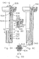
- Figure 8A shows the activating pin in activated position where an axially slidable valve 534 has a seal face 535.
- the air flows through a proximal (to the pressure source) gradual expansion 536 of the center drilling 533 and through the latter to the distal gradual expansion 537.
- the wall 538,539 forms an angle ⁇ or ⁇ , respectively, to the wall 540 of the center drilling 533. These are larger than 0° and smaller than 20° (usually in the interval between 6° and 12°).
- Both expansions 536,537 have an approximately circular cross section distally from the connection to the center drilling 533. Also shown are the center axis 543 and the piston valve rod 544.
- Figure 8B shows the section D-D from figure 8A where the channel 533 is defined by a "flower-shaped" cross section of the piston rod 532 and a circular cross section of the valve rod 544. Furthermore, a fin 542 is shown.
- Figure 8C shows the activating pin with a closed valve.
- the spring 541 secured in the piston 531 is an elastic band which presses the axially slidable valve 534 down so that the seal face 535 of the valve is pressed against the wall 538 of the expansion 536.
- the seal face 535 can have a similar sealing (not showed) with the wall 538 as showed in Figure 11A, 11B.
- Figure 8D shows an improved sealing surface arrangement: sealing 550 with surface 551 and piston rod 553 with sealing surface 552.
- Angle ⁇ is between 90°-150° (incl.).
- the channel 546 is defined by the sealing surfaces 551 and 552, when these are seperated from each other.
- Figure 9 shows a sixth embodiment with the piston 651 in its distal position relative to the pressure source in a coupling house of a valve connector that can be squeezed onto valves.
- the piston 651 has a piston rod 652 and is equipped with a center drilling 653.
- Figure 10A shows the activating pin in its closed position and its activated position (broken lines) where the axially slidable valve 654 has a seal face 655.
- the air flows through the expansion 656 of the center drilling 653 and through the latter to the distal gradual expansion 657 and the distal part of the piston rod with a "flower-shaped" cross section.
- the wall 658,659 forms an angle ⁇ or ⁇ , respectively, to the wall 660 of the center drilling 653. These angles are each larger than 0° and smaller than 20° (usually in the interval between 6° and 12°). Both expansions 656,657 have an approximately circular cross section.
- the valve 654 has a spring part 661 secured in a brace 662.
- the activating pin has at least one fin or brace 663. Furthermore, a cone 664 is shown.
- Figure 10B shows the top (view Y) of the activating pin shown in figure 10A with the three expansions 656 and braces 662.
- the braces serve as a securing device for the valve spring and the expansions 656 ensure a suitable flow cross section.
- Figure 10C shows the section E-E in figure 10A resulting in a cylindrical air channel 653. A suitable flow cross section is also ensured here.
- Figure 10D shows the section F-F in figure 10A. Internally, this section of the piston rod 652 is "flower-shaped" to ensure a suitable flow cross section. Furthermore, a fin designed as a brace 663 is shown. Also shown is the channel 666 between the brace 663 and the piston rod 652.
- Figure 11A shows an activating pin similar to the one of Figure 10, with the sealing surface 704 of the cone 702 and the corresponding surface 703 for the piston rod 701 having an angle ⁇ equal to or larger than 90° and less than approximately 150° with the center axis 665 seen in the direction of the flow of the air at flow from the pressure source.
- Channel 705 is defined by the sealing surface 703 and 704, when these are seperated from each other.
Landscapes
- Engineering & Computer Science (AREA)
- General Engineering & Computer Science (AREA)
- Mechanical Engineering (AREA)
- Lift Valve (AREA)
- Check Valves (AREA)
- Organic Low-Molecular-Weight Compounds And Preparation Thereof (AREA)
- Pistons, Piston Rings, And Cylinders (AREA)
- Compressor (AREA)
- Pens And Brushes (AREA)
- Photoreceptors In Electrophotography (AREA)
- Earth Drilling (AREA)
- Mechanically-Actuated Valves (AREA)
- Valve-Gear Or Valve Arrangements (AREA)
- Saccharide Compounds (AREA)
- Compressors, Vaccum Pumps And Other Relevant Systems (AREA)
- Fluid-Driven Valves (AREA)
- Fuel-Injection Apparatus (AREA)
Claims (19)
- Broche d'activation pour un raccord de valve destiné à être raccordé à des valves de gonflage, le raccord comprenantcaractérisé en ce queun boítier devant être raccordé à une source de pression,dans le boítierun orifice de couplage possédant un axe central et un diamètre intérieur correspondant approximativement au diamètre extérieur de la valve de gonflage, à laquelle le raccord de valve doit être raccordé, etun cylindre et des moyens pour véhiculer des milieux gazeux entre le cylindre et la source de pression, et laquelle broche d'activationest agencée de manière à coopérer avec un levier de valve central, actionné par la force d'un ressort, de la valve de gonflage,est agencée de manière à être située dans le boítier à la suite de l'orifice de couplage, coaxialement à l'axe central de ce dernier, etcomprend une partie à piston (121,122,131,222,223,301, 302,306,307,309,318,338,406,407,408,409,414,420,531,532, 541, 553,651,652,662,663,701) pourvue d'un piston, lequel piston doit être positionné dans le cylindre de manière à être déplaçable entre une première position et une seconde position,la broche d'activation comprenant une partie de valve (126,126a,225,227,231,238,304,306,315,316,317,322,401, 414,534,535,542,544,550,654,661,664,702),ladite partie de valve (126,126a,225,227,231,238,304,306, 315,316,317,322,401,414,534,535,542,544,550,654,661,664, 702) étant positionnée de manière à être déplaçable par rapport à ladite partie à piston (121,122,131,222,223, 301,302,306,307,309,318,338,406,407,408,409,414,420,531, 532,541,553,651,652,662,663,701) entre une première position et une seconde position de valve, pourpermettre le transfert d'un milieu gazeux et/ou liquide par ledit canal lorsque ladite partie de valve est située dans ladite première position de valve, etempêcher le transfert d'un milieu gazeux et/ou liquide par ledit canal lorsque ladite partie de valve est située dans ladite seconde position de valve,la partie à piston (121,122,131,222,223,301,302,306,307, 309,318,338,406,407,408,409,414,420,531,532,541,553,651, 652,662,663,701) contient en elle un canal (123,124,127, 128,224,234,242,244,247,303,310,311,321,324,325,410,416, 417,418,419,422,423,533,536,537,546,653,656,657,666,705),la section transversale dudit canal est, dans au moins une portion de ladite partie à piston, conformée en forme de fleur et est constituée de secteurs essentiellement identiques, la distance, dans chaque secteur, entre le point central de la section transversale du canal et la surface limite la plus extérieure du canal étant inférieure à la distance correspondante mesurée le long de la ligne séparant le secteur d'un secteur adjacent.
- Broche d'activation selon la revendication 1 dans un raccord de valve destiné à être raccordé à des valves de gonflage, caractérisée en ce que ladite partie à piston (121, 122) comprend une première extrémité et une seconde extrémité, et dans laquelle le piston (121) est situé au niveau de ladite première extrémité et ledit canal (123, 124) comprendun premier perçage borgne (123) s'étendant dans la direction longitudinale de ladite partie à piston (121) au niveau de la première extrémité de ladite partie à piston (121),un premier perçage radial (124) raccordant l'extrémité aveugle dudit perçage borgne (123) à un premier orifice dans la surface de ladite partie à piston (121, 122);et ladite partie de valve (126) est un élément élastique agencé de manière à laisser ouvert ledit premier orifice, lorsque la valve est dans ladite première position, et à fermer ledit premier orifice, lorsque la valve est dans ladite seconde position.
- Broche d'activation selon la revendication 2 dans un raccord de valve destiné à être raccordé à des valves de gonflage, caractérisée en ce que ledit canal (127, 128) comprendun second perçage borgne (128) dans la direction longitudinale de ladite partie à piston (121, 122) au niveau de la première extrémité de ladite partie à piston (121, 122),un second perçage radial (127) raccordant l'extrémité aveugle dudit second perçage borgne (128) à un second orifice de la surface de ladite partie à piston (121, 122).
- Broche d'activation selon la revendication 2 dans un raccord de valve destiné à être raccordé à des valves de gonflage, caractérisé en ce que l'angle α entre l'axe dudit premier perçage borgne (123) et l'axe dudit premier perçage radial (124) est supérieur ou égal à 90°.
- Broche d'activation selon la revendication 3 dans un raccord de valve destiné à être raccordé à des valves de gonflage, caractérisée en ce que l'angle β entre l'axe (125) dudit second perçage aveugle (128) et l'axe dudit second perçage radial (127) est supérieur ou égal à 90°.
- Broche d'activation selon la revendication 2 dans un raccord de valve destiné à être raccordé à des valves de gonflage, caractérisée en ce qu'au moins l'un dudit premier perçage borgne (123) et dudit second perçage aveugle (128) possède une surface en coupe transversale qui est plus grande au niveau de son extrémité ouverte qu'au niveau de son extrémité fermée.
- Broche d'activation selon la revendication 1 dans un raccord de valve destiné à être raccordé à des valves de gonflage, caractérisée en ce quedans laquelle ladite première position de la valve correspond à une rotation de ladite partie de valve (401) autour dudit axe de rotation (404) pour venir dans une position dans laquelle elle laisse ouverte ladite ouverture, et ladite seconde position de la valve correspond à une rotation de ladite partie de valve (401) autour dudit axe de rotation (403) pour venir dans une position dans laquelle elle ferme ladite ouverture.ladite partie à piston (407, 409, 420) comprend une première extrémité et une seconde extrémité, le piston (407) étant situé sur ladite première extrémité et ledit canal (303, 418) possédant une ouverture située au niveau de ladite première extrémité, etladite partie de valve (401) est agencée de manière à tourner autour d'un axe de rotation (404) monté sur ladite première extrémité perpendiculairement à l'axe longitudinal (403) de ladite partie à piston (407,409,420);
- Broche d'activation selon la revendication 7 dans un raccord de valve destiné à être raccordé à des valves de gonflage, caractérisée en ce qu'elle comprend des moyens (402) pour ramener ladite partie de valve (401) dans ladite première position de la valve lorsque le piston est dans sa première position.
- Broche d'activation selon la revendication 7 dans un raccord pour valve destiné à être raccordé à des valves de gonflage, caractérisée en ce que ledit canal (303) comprend un perçage dans la direction longitudinale de ladite partie à piston (407, 409, 420), ledit perçage possédant dans une surface en coupe transversale qui est plus grande au niveau d'au moins une extrémité ouverte qu'au milieu entre ses extrémités ouvertes.
- Broche d'activation selon la revendication 9 dans un raccord de valve destiné à être raccordé à des valves de gonflage, caractérisée en ce que ladite partie de valve (225,227,302,304,322,353,534,544,654,661,702) est agencée de manière à se déplacer par rapport à ladite partie à piston (222,223,301,302,531,532,553,651,652,701) dans la direction longitudinale de ladite partie à piston (222,223,301,302,531,532,553,651,652,701).
- Broche d'activation selon la revendication 10 dans un raccord de valve destiné à être raccordé à des valves de gonflage, caractérisée en ce quedans laquelle ladite première position de la valve correspond à un déplacement de ladite partie de valve (225, 227) dans la direction longitudinale de ladite partie à piston (222, 223) dans une position dans laquelle l'extrémité libre (228) de ladite tige de valve (227) laisse ouvert le point de transition entre ladite première partie de canal (224) et ladite seconde partie de canal (228), et ladite seconde position de valve correspond à un déplacement de ladite valve (225, 227) dans la direction longitudinale de ladite partie à piston (222, 223) dans une position dans laquelle l'extrémité libre (228) de ladite tige de valve (227) ferme le point de transition entre ladite première partie de canal (227) et ladite seconde partie de canal (228).ladite partie à piston (222, 223) comprend une première extrémité et une seconde extrémité, le piston (222) étant situé au niveau de ladite première extrémité,ledit canal (224, 248) comprend une première partie de canal (224) et une seconde partie de canal (248) tous deux dans la direction longitudinale de ladite partie à piston (222, 223) et raccordées entre elles au niveau d'un point de transition, etladite partie de valve (225, 227) comprend une tige de valve (227) agencée de manière à se déplacer dans ladite première partie de canal (224) et comportant une extrémité libre (228);
- Broche d'activation selon la revendication 11 dans un raccord de valve destiné à être raccordé à des valves de gonflage, caractérisée en ce qu'au moins une extrémité de ladite première partie de canal (224) et ladite seconde partie de canal (248) possèdent une surface en coupe transversale plus grande à son autre extrémité qu'au niveau de son extrémité la plus proche dudit point de transition.
- Broche d'activation selon la revendication 11 dans un raccord de valve destiné à être raccordé à des valves de gonflage, caractérisée en ce qu'elle comprend des moyens d'arrêt (231) servant à limiter le déplacement de ladite partie de valve (227) dans la direction longitudinale de ladite partie de piston (223).
- Broche d'activation selon la revendication 10, dans un raccord de valve destiné à être raccordé à des valves de gonflage, caractérisée en ce que ladite partie à piston (301, 302) comprend une première extrémité et une seconde extrémité, le piston (301) étant situé au niveau de ladite première extrémité,dans laquelle ladite première position de la valve correspond au fait que ladite partie de valve (304,322,316,353) est déplacée dans la direction longitudinale de ladite partie à piston (301, 302) dans une position, dans laquelle ledit élément d'étanchéité de valve (306) laisse ouverte l'ouverture circulaire dudit perçage (303,310) dans ladite première extrémité, et ladite seconde position de valve correspond à un déplacement de ladite partie de valve (304,322,316,353) dans la direction longitudinale de ladite partie à piston (301, 302) dans une position dans laquelle ledit capuchon de valve ferme l'ouverture circulaire dudit perçage (303, 311) situé au niveau de ladite première extrémité.ledit canal (303,310,311,321,324) comprend un perçage (303) s'étendant depuis la première extrémité (310) en direction de ladite seconde extrémité (311), l'ouverture dudit perçage dans ladite première extrémité étant circulaire, etladite partie de valve (304,322,316,353) comprendune tige de valve (322) comportant un canal (321) disposée dans la direction longitudinale de ladite partie de valve (304,322,316,353), ladite tige de valve (322) étant agencée de manière à se déplacer dans ledit perçage (303, 310), etun élément cylindrique d'étanchéité de valve (306) situé à une extrémité de ladite tige de valve (322), l'axe (337) dudit élément cylindrique d'étanchéité de valve (306) s'étendant dans la direction longitudinale de ladite partie à piston (304,322,316,353), dudit perçage (303, 310) et de ladite tige de valve (322), et le diamètre extérieur dudit élément d'étanchéité de valve (306) étant supérieur au diamètre de l'ouverture circulaire dudit perçage (310) présent dans ladite première extrémité;
- Broche d'activation selon la revendication 14 dans un raccord de valve destiné à être raccordé à des valves de gonflage, caractérisé en ce qu'elle comprend des moyens (305, 350) pour entraíner ladite partie de valve (304,322,3156,353) pour l'amener dans ladite première position de valve lorsque le piston (301) est dans sa première position.
- Broche d'activation selon la revendication 10 dans un raccord de valve destiné à être raccordé à des valves de gonflage, caractérisée en ce quedans laquelle ladite première position de valve correspond à un déplacement de ladite partie de valve (544,654,702) dans la direction longitudinale de ladite partie à piston (531,532,651,652) dans une position dans laquelle elle laisse subsister un intervalle (530) entre ladite première surface d'étanchéité (536,659,703) et ladite seconde surface d'étanchéité (535,655,704), et ladite seconde position de valve correspond à un déplacement de ladite partie de valve (544,654,702) dans la direction longitudinale de ladite partie à piston (531,532,651,652) dans une position dans laquelle ladite première surface d'étanchéité (538,659,703) est repoussée contre ladite seconde surface d'étanchéité (535,655,704).ladite partie à piston (531,532,651,652,701) comprend une première extrémité et une seconde extrémité, le piston (531, 651) étant situé dans ladite première extrémité,ledit canal (533,536,537,653,656,657,666) comprend un perçage (533, 653) qui s'étend depuis ladite première extrémité jusqu'à ladite seconde extrémité, ledit perçage possédant, en un point prédéterminé entre ladite première extrémité et ladite seconde extrémité, une section transversale circulaire et formant une première surface d'étanchéité (536,659,703), etladite partie de valve (544,654,702) est agencée de manière à se déplacer dans ledit perçage (533, 653) et comprend une seconde surface d'étanchéité conique (535, 655,704),
- Broche d'activation selon la revendication 16 dans un raccord de valve destiné à être raccordé à des valves de gonflage, caractérisée en ce que dans ladite seconde position de la valve, ladite partie de valve (544) est plus proche de la seconde extrémité de ladite partie à piston (531, 532) que dans ladite première position de la valve, et que la broche d'activation comprend un élément élastique (541) servant à amener lesdits moyens de valve (534) dans ladite seconde position.
- Broche d'activation selon la revendication 16 dans un raccord de valve destiné à être raccordé à des valves de gonflage, caractérisée en ce que, dans ladite première position de la valve, ladite partie de valve (654, 702) est plus proche de la seconde extrémité et de ladite partie à piston (651,652,701) que dans ladite seconde position de la valve.
- Utilisation d'une broche d'activation selon la revendication 1 dans un raccord de valve destiné à être raccordé à des valves de gonflage.
Priority Applications (3)
| Application Number | Priority Date | Filing Date | Title |
|---|---|---|---|
| EP20040003470 EP1437540A3 (fr) | 1996-05-14 | 1997-05-14 | Aiguille de commande |
| SI9730644T SI0906529T1 (en) | 1996-05-14 | 1997-05-14 | Activation pin |
| DK97921647T DK0906529T3 (da) | 1996-05-14 | 1997-05-14 | Aktiveringsstift |
Applications Claiming Priority (9)
| Application Number | Priority Date | Filing Date | Title |
|---|---|---|---|
| DK9600168U DK9600168U3 (da) | 1996-05-14 | 1996-05-14 | Ventilkobling |
| DK16896 | 1996-05-14 | ||
| DK9600180U DK9600180U3 (da) | 1996-05-14 | 1996-05-24 | Ventilkobling |
| DK18096 | 1996-05-24 | ||
| DK22796 | 1996-06-28 | ||
| DK9600227U DK9600227U3 (da) | 1996-05-24 | 1996-06-28 | Ventilkobling |
| DK4897 | 1997-01-31 | ||
| DK9700048U DK9700048U3 (da) | 1996-05-14 | 1997-01-31 | aktiveringspind til ventilkobling |
| PCT/DK1997/000223 WO1997043570A1 (fr) | 1996-05-14 | 1997-05-14 | Aiguille de commande |
Related Child Applications (1)
| Application Number | Title | Priority Date | Filing Date |
|---|---|---|---|
| EP20040003470 Division EP1437540A3 (fr) | 1996-05-14 | 1997-05-14 | Aiguille de commande |
Publications (2)
| Publication Number | Publication Date |
|---|---|
| EP0906529A1 EP0906529A1 (fr) | 1999-04-07 |
| EP0906529B1 true EP0906529B1 (fr) | 2004-02-18 |
Family
ID=27439774
Family Applications (2)
| Application Number | Title | Priority Date | Filing Date |
|---|---|---|---|
| EP19970921647 Expired - Lifetime EP0906529B1 (fr) | 1996-05-14 | 1997-05-14 | Aiguille de commande |
| EP20040003470 Withdrawn EP1437540A3 (fr) | 1996-05-14 | 1997-05-14 | Aiguille de commande |
Family Applications After (1)
| Application Number | Title | Priority Date | Filing Date |
|---|---|---|---|
| EP20040003470 Withdrawn EP1437540A3 (fr) | 1996-05-14 | 1997-05-14 | Aiguille de commande |
Country Status (27)
| Country | Link |
|---|---|
| US (1) | US6378547B1 (fr) |
| EP (2) | EP0906529B1 (fr) |
| JP (1) | JP2000514527A (fr) |
| KR (2) | KR20000010997A (fr) |
| CN (2) | CN1119542C (fr) |
| AP (1) | AP9801413A0 (fr) |
| AT (1) | ATE259954T1 (fr) |
| AU (2) | AU739666B2 (fr) |
| BR (1) | BR9709242A (fr) |
| CA (1) | CA2254964A1 (fr) |
| CY (1) | CY2467B1 (fr) |
| DE (1) | DE69727678T2 (fr) |
| DK (2) | DK9700048U3 (fr) |
| EA (1) | EA000511B1 (fr) |
| ES (1) | ES2218678T3 (fr) |
| HU (1) | HUP9904704A3 (fr) |
| NO (2) | NO985269L (fr) |
| NZ (2) | NZ505701A (fr) |
| OA (1) | OA10923A (fr) |
| PL (1) | PL184214B1 (fr) |
| PT (1) | PT906529E (fr) |
| RO (1) | RO119137B1 (fr) |
| SI (1) | SI0906529T1 (fr) |
| SK (1) | SK155998A3 (fr) |
| TW (2) | TW363924B (fr) |
| UA (1) | UA73068C2 (fr) |
| WO (1) | WO1997043570A1 (fr) |
Families Citing this family (14)
| Publication number | Priority date | Publication date | Assignee | Title |
|---|---|---|---|---|
| CN1143958C (zh) | 1995-02-03 | 2004-03-31 | Nvb国际公司 | 气门嘴接头 |
| TW363924B (en) | 1996-05-14 | 1999-07-11 | Nvb Int | Activation pin for valve connector providing a reliable activation pin which is inexpensive, has low air-power resistance, and is therefore suitable for use as pump |
| US6648005B2 (en) | 1998-11-13 | 2003-11-18 | Nvb International | Activation pin |
| ES2337031T3 (es) | 2001-03-27 | 2010-04-20 | Nvb Composites International A/S | Una combinacion de una camara y un piston, una bomba, un motor, un amortiguador y un transductor que incorpora la combinacion. |
| TW201207237A (en) * | 2010-08-03 | 2012-02-16 | Shu-Mu Wu | Air pump head |
| TW201235565A (en) | 2011-02-25 | 2012-09-01 | Nvb Composites Internat Uk Ltd | Piston-chamber combination vanderblom motor |
| EP2917611A1 (fr) | 2011-07-01 | 2015-09-16 | NVB Composites International UK Ltd | Ensemble piston/chambre - moteur vanderblom |
| US9328834B2 (en) * | 2014-04-30 | 2016-05-03 | Beto Engineering & Marketing Co., Ltd. | Air valve connecting device |
| CN104595537B (zh) * | 2014-12-24 | 2017-01-18 | 宁波五马实业有限公司 | 一种快速安装的气嘴接头 |
| TWI632317B (zh) * | 2017-09-12 | 2018-08-11 | 雙餘實業股份有限公司 | Inflatable joint |
| WO2019193744A1 (fr) * | 2018-04-06 | 2019-10-10 | 太平洋工業株式会社 | Valve de pneu |
| TWI665401B (zh) * | 2018-08-21 | 2019-07-11 | 許龍國 | 氣嘴接頭具自動止氣結構 |
| US11085549B1 (en) | 2019-03-26 | 2021-08-10 | Pacific Industrial Co., Ltd. | Valve |
| US11168678B2 (en) * | 2020-03-05 | 2021-11-09 | Scott Wu | Inflation pump |
Family Cites Families (41)
| Publication number | Priority date | Publication date | Assignee | Title |
|---|---|---|---|---|
| US1492838A (en) | 1917-11-26 | 1924-05-06 | Lloyd W Dilweg | Device for transmitting compressed air to automob ile tires |
| GB231992A (en) | 1924-02-29 | 1925-04-16 | Dunlop Rubber Co | An improved connection for fitment to valves of pneumatic tyres |
| US1850111A (en) | 1928-09-10 | 1932-03-22 | Paul C Swole | Combined air gauge and self closing outlet fitting |
| US2025067A (en) | 1934-12-17 | 1935-12-24 | Thomas S Miller | Tank filling device |
| US2257498A (en) | 1939-10-10 | 1941-09-30 | Clarence K Hansen | Tire inflation apparatus |
| US2489397A (en) * | 1944-05-05 | 1949-11-29 | Brummer Henry | Tire valve operating device |
| US2716998A (en) | 1949-03-02 | 1955-09-06 | Joseph J Knasko | Combined tire inflating chuck, deflator and blow gun |
| US2685906A (en) | 1952-01-19 | 1954-08-10 | Scovill Manufacturing Co | Running inflation and deflation system |
| GB872246A (en) | 1956-08-03 | 1961-07-05 | Walters & Dobson Ltd | Improvements in or relating to tyre valve connectors |
| US2976906A (en) | 1958-09-10 | 1961-03-28 | Wunibald I E Kamm | Tire pressure control device |
| GB977139A (en) | 1962-10-15 | 1964-12-02 | Walters & Dobson Ltd | Improvements in or relating to tyre valve connectors |
| US3249144A (en) | 1964-09-23 | 1966-05-03 | Berg Mfg & Sales Co | Tire pressure system and valve |
| FR2180164A5 (fr) | 1972-04-11 | 1973-11-23 | Poutrait Morin | |
| US3911988A (en) * | 1974-02-21 | 1975-10-14 | Eaton Corp | Pressurization control device |
| DE2544555A1 (de) * | 1975-10-04 | 1977-04-07 | Magirus Deutz Ag | Vorrichtung zur steuerung des luftdruckes im reifen eines fahrzeuges |
| IT1056460B (it) * | 1976-02-04 | 1982-01-30 | Dante B | Corpo valvolare per valvole per pneumatici |
| US4088147A (en) | 1976-07-09 | 1978-05-09 | Control Devices, Incorported | Air chuck |
| GB1599304A (en) | 1977-09-23 | 1981-09-30 | Scovill Inc | Inflation valve connectors |
| US4165760A (en) | 1977-10-17 | 1979-08-28 | Guenther Manfred H | Air chuck |
| US4489855A (en) | 1982-08-27 | 1984-12-25 | Code Manufacturing, Inc. | Instant tire inflator |
| WO1984002968A1 (fr) | 1983-01-27 | 1984-08-02 | Precision Valve Corp | Connecteur de valve de pneumatique |
| FR2552851B1 (fr) | 1983-09-30 | 1986-08-14 | Poutrait Morin | Embouts destines a etre fixes aux extremites d'un conduit flexible, pour constituer un raccord utilisable sur une pompe portative pour le gonflage de pneumatiques, et raccord comportant de tels embouts |
| DE8602739U1 (de) * | 1986-02-03 | 1987-10-01 | Alligator Ventilfabrik GmbH, 7928 Giengen | Ventil für Luftreifen |
| US4662412A (en) | 1986-05-13 | 1987-05-05 | Peter Bergmann | Inflating device for use single-handed |
| US4712812A (en) | 1986-09-02 | 1987-12-15 | Weir Iii Joseph W | Universal fittings |
| DE3729327A1 (de) * | 1987-09-02 | 1989-03-16 | Bosch Gmbh Robert | Reifendruck-steuerventil iii |
| DE3819771A1 (de) | 1987-12-18 | 1989-07-06 | Karl Scheffer Klute Gmbh & Co | Handluftpumpe fuer zweiradreifen |
| US4901747A (en) * | 1988-06-29 | 1990-02-20 | David Moliver | Tire inflation valve with pressure indicator |
| US4932451A (en) | 1989-01-26 | 1990-06-12 | General Motors Corporation | Vehicle wheel end assembly with air passage |
| US4938272A (en) | 1989-01-26 | 1990-07-03 | General Motors Corporation | Valve actuator for tire pressure management |
| FR2653523B3 (fr) | 1989-10-19 | 1991-10-04 | Hernandez Manuel | Raccord d'adaptation d'une bonbonne de gaz comprime a une valve de gonflage de pneu. |
| US5012954A (en) | 1990-02-08 | 1991-05-07 | Will Conrad A | Tire inflation system |
| DE4120188C1 (fr) | 1991-06-19 | 1992-09-17 | Cramer Gmbh & Co Kg, 5750 Menden, De | |
| US5094263A (en) * | 1991-08-02 | 1992-03-10 | General Motors Corporation | Tire pressure management actuator with bypass leakage prevention |
| CN1143958C (zh) | 1995-02-03 | 2004-03-31 | Nvb国际公司 | 气门嘴接头 |
| US5778923A (en) * | 1995-10-25 | 1998-07-14 | Marston; Philip William | Anti-seepage self-gauging inflation valve system |
| DE19601952A1 (de) | 1996-01-09 | 1997-07-10 | Gruener Uko Picasso | Luftdruckrohr-Flasche mit Ventil |
| TW390942B (en) * | 1996-04-22 | 2000-05-21 | Schwinn Cycling & Fitness Inc | Combination pump head |
| TW363924B (en) | 1996-05-14 | 1999-07-11 | Nvb Int | Activation pin for valve connector providing a reliable activation pin which is inexpensive, has low air-power resistance, and is therefore suitable for use as pump |
| US5785076A (en) * | 1996-05-20 | 1998-07-28 | You; Bae-Jou | Inflating assembly for tire |
| US5819781A (en) * | 1997-07-28 | 1998-10-13 | Wu; Scott | Pumping device with a pivotal lever for various valves |
-
1996
- 1996-07-19 TW TW085108785A patent/TW363924B/zh active
-
1997
- 1997-01-31 DK DK9700048U patent/DK9700048U3/da not_active IP Right Cessation
- 1997-05-14 ES ES97921647T patent/ES2218678T3/es not_active Expired - Lifetime
- 1997-05-14 AU AU27648/97A patent/AU739666B2/en not_active Ceased
- 1997-05-14 NZ NZ505701A patent/NZ505701A/en not_active IP Right Cessation
- 1997-05-14 CN CN97194692A patent/CN1119542C/zh not_active Expired - Fee Related
- 1997-05-14 CA CA 2254964 patent/CA2254964A1/fr not_active Abandoned
- 1997-05-14 EA EA199801014A patent/EA000511B1/ru not_active IP Right Cessation
- 1997-05-14 UA UA98126591A patent/UA73068C2/uk unknown
- 1997-05-14 PT PT97921647T patent/PT906529E/pt unknown
- 1997-05-14 US US09/180,689 patent/US6378547B1/en not_active Expired - Fee Related
- 1997-05-14 DE DE1997627678 patent/DE69727678T2/de not_active Expired - Fee Related
- 1997-05-14 EP EP19970921647 patent/EP0906529B1/fr not_active Expired - Lifetime
- 1997-05-14 PL PL97329876A patent/PL184214B1/pl not_active IP Right Cessation
- 1997-05-14 AP APAP/P/1998/001413A patent/AP9801413A0/en unknown
- 1997-05-14 HU HU9904704A patent/HUP9904704A3/hu unknown
- 1997-05-14 WO PCT/DK1997/000223 patent/WO1997043570A1/fr not_active Ceased
- 1997-05-14 KR KR1019980709146A patent/KR20000010997A/ko not_active Abandoned
- 1997-05-14 KR KR1020027006153A patent/KR100613121B1/ko not_active Expired - Fee Related
- 1997-05-14 RO RO98-01576A patent/RO119137B1/ro unknown
- 1997-05-14 CN CNB031465013A patent/CN100353104C/zh not_active Expired - Fee Related
- 1997-05-14 EP EP20040003470 patent/EP1437540A3/fr not_active Withdrawn
- 1997-05-14 JP JP54040997A patent/JP2000514527A/ja not_active Ceased
- 1997-05-14 SI SI9730644T patent/SI0906529T1/xx unknown
- 1997-05-14 AT AT97921647T patent/ATE259954T1/de not_active IP Right Cessation
- 1997-05-14 BR BR9709242A patent/BR9709242A/pt not_active IP Right Cessation
- 1997-05-14 DK DK97921647T patent/DK0906529T3/da active
- 1997-05-14 SK SK1559-98A patent/SK155998A3/sk unknown
- 1997-05-14 NZ NZ33332797A patent/NZ333327A/xx not_active IP Right Cessation
-
1998
- 1998-04-10 TW TW085108785A patent/TW487654B/zh active
- 1998-11-11 NO NO19985269A patent/NO985269L/no not_active Application Discontinuation
- 1998-11-13 OA OA9800221A patent/OA10923A/en unknown
-
2004
- 2004-05-19 CY CY0400058A patent/CY2467B1/xx unknown
- 2004-12-09 NO NO20045378A patent/NO20045378L/no not_active Application Discontinuation
-
2005
- 2005-05-19 AU AU2005202130A patent/AU2005202130A1/en not_active Abandoned
Also Published As
Similar Documents
| Publication | Publication Date | Title |
|---|---|---|
| US6378547B1 (en) | Activation pin | |
| US6510868B2 (en) | Profiled plate valve | |
| US2538364A (en) | Valve | |
| US4466461A (en) | Valve | |
| US3443793A (en) | Variable area orifice,rotary control valve | |
| CN107461506B (zh) | 具有弯曲凹口的阀塞 | |
| US6401744B1 (en) | Valve actuator | |
| US6648005B2 (en) | Activation pin | |
| AU2003204640B2 (en) | Precision modulating globe valve | |
| US5983928A (en) | Gas safety valve | |
| EP1246036A3 (fr) | Vanne de régulation de débit | |
| HK1069867A (en) | Activation pin | |
| AU1192702A (en) | Activating pin | |
| EP4421376B1 (fr) | Connecteur de gonflage | |
| AU2008201059A1 (en) | Activating pin | |
| KR200370212Y1 (ko) | 밸브의 작동상태를 표시하는 작동핀이 부착된 공압 밸브 | |
| CA1340054C (fr) | Distributeur modulaire sans joint d'etancheite | |
| KR20040096465A (ko) | 밸브의 작동상태를 표시하는 작동핀이 부착된 공압 밸브 | |
| CA2369417A1 (fr) | Systeme de recuperation pour puits artesiens, puits de petrole et puits de gaz |
Legal Events
| Date | Code | Title | Description |
|---|---|---|---|
| PUAI | Public reference made under article 153(3) epc to a published international application that has entered the european phase |
Free format text: ORIGINAL CODE: 0009012 |
|
| 17P | Request for examination filed |
Effective date: 19981216 |
|
| AK | Designated contracting states |
Kind code of ref document: A1 Designated state(s): AT BE CH DE DK ES FI FR GB GR IE IT LI LU MC NL PT SE |
|
| AX | Request for extension of the european patent |
Free format text: AL PAYMENT 981216;LT PAYMENT 981216;LV PAYMENT 981216;RO PAYMENT 981216;SI PAYMENT 981216 |
|
| 17Q | First examination report despatched |
Effective date: 20010709 |
|
| GRAH | Despatch of communication of intention to grant a patent |
Free format text: ORIGINAL CODE: EPIDOS IGRA |
|
| GRAS | Grant fee paid |
Free format text: ORIGINAL CODE: EPIDOSNIGR3 |
|
| GRAA | (expected) grant |
Free format text: ORIGINAL CODE: 0009210 |
|
| AK | Designated contracting states |
Kind code of ref document: B1 Designated state(s): AT BE CH DE DK ES FI FR GB GR IE IT LI LU MC NL PT SE |
|
| AX | Request for extension of the european patent |
Extension state: AL LT LV RO SI |
|
| REG | Reference to a national code |
Ref country code: GB Ref legal event code: FG4D |
|
| REG | Reference to a national code |
Ref country code: CH Ref legal event code: EP |
|
| REG | Reference to a national code |
Ref country code: IE Ref legal event code: FG4D |
|
| REF | Corresponds to: |
Ref document number: 69727678 Country of ref document: DE Date of ref document: 20040325 Kind code of ref document: P |
|
| PG25 | Lapsed in a contracting state [announced via postgrant information from national office to epo] |
Ref country code: IE Free format text: LAPSE BECAUSE OF NON-PAYMENT OF DUE FEES Effective date: 20040514 |
|
| PGFP | Annual fee paid to national office [announced via postgrant information from national office to epo] |
Ref country code: ES Payment date: 20040526 Year of fee payment: 8 |
|
| PGFP | Annual fee paid to national office [announced via postgrant information from national office to epo] |
Ref country code: FR Payment date: 20040528 Year of fee payment: 8 |
|
| PG25 | Lapsed in a contracting state [announced via postgrant information from national office to epo] |
Ref country code: LU Free format text: LAPSE BECAUSE OF NON-PAYMENT OF DUE FEES Effective date: 20040531 |
|
| REG | Reference to a national code |
Ref country code: SE Ref legal event code: TRGR |
|
| REG | Reference to a national code |
Ref country code: GR Ref legal event code: EP Ref document number: 20040401724 Country of ref document: GR |
|
| REG | Reference to a national code |
Ref country code: CH Ref legal event code: NV Representative=s name: WALDER WYSS & PARTNER RECHTSANWAELTE |
|
| REG | Reference to a national code |
Ref country code: DK Ref legal event code: T3 |
|
| REG | Reference to a national code |
Ref country code: PT Ref legal event code: SC4A Free format text: AVAILABILITY OF NATIONAL TRANSLATION Effective date: 20040518 |
|
| REG | Reference to a national code |
Ref country code: ES Ref legal event code: FG2A Ref document number: 2218678 Country of ref document: ES Kind code of ref document: T3 |
|
| ET | Fr: translation filed | ||
| PLBE | No opposition filed within time limit |
Free format text: ORIGINAL CODE: 0009261 |
|
| STAA | Information on the status of an ep patent application or granted ep patent |
Free format text: STATUS: NO OPPOSITION FILED WITHIN TIME LIMIT |
|
| REG | Reference to a national code |
Ref country code: SI Ref legal event code: IF |
|
| 26N | No opposition filed |
Effective date: 20041119 |
|
| REG | Reference to a national code |
Ref country code: IE Ref legal event code: MM4A |
|
| PG25 | Lapsed in a contracting state [announced via postgrant information from national office to epo] |
Ref country code: ES Free format text: LAPSE BECAUSE OF NON-PAYMENT OF DUE FEES Effective date: 20050516 |
|
| PG25 | Lapsed in a contracting state [announced via postgrant information from national office to epo] |
Ref country code: LI Free format text: LAPSE BECAUSE OF NON-PAYMENT OF DUE FEES Effective date: 20050531 |
|
| PGFP | Annual fee paid to national office [announced via postgrant information from national office to epo] |
Ref country code: AT Payment date: 20051130 Year of fee payment: 9 |
|
| REG | Reference to a national code |
Ref country code: CH Ref legal event code: PL |
|
| PG25 | Lapsed in a contracting state [announced via postgrant information from national office to epo] |
Ref country code: FR Free format text: LAPSE BECAUSE OF NON-PAYMENT OF DUE FEES Effective date: 20060131 |
|
| REG | Reference to a national code |
Ref country code: FR Ref legal event code: ST Effective date: 20060131 |
|
| REG | Reference to a national code |
Ref country code: CH Ref legal event code: AEN Free format text: DAS PATENT IST AUFGRUND DES WEITERBEHANDLUNGSANTRAGS VOM 28.02.2006 REAKTIVIERT WORDEN. |
|
| PG25 | Lapsed in a contracting state [announced via postgrant information from national office to epo] |
Ref country code: AT Free format text: LAPSE BECAUSE OF NON-PAYMENT OF DUE FEES Effective date: 20060514 |
|
| REG | Reference to a national code |
Ref country code: IE Ref legal event code: NE4A |
|
| REG | Reference to a national code |
Ref country code: ES Ref legal event code: FD2A Effective date: 20050516 |
|
| LTLA | Lt: lapse of european patent or patent extension |
Effective date: 20060514 |
|
| REG | Reference to a national code |
Ref country code: SI Ref legal event code: KO00 Effective date: 20070209 |
|
| REG | Reference to a national code |
Ref country code: IE Ref legal event code: NF4A Effective date: 20071217 |
|
| REG | Reference to a national code |
Ref country code: PT Ref legal event code: MM4A Free format text: LAPSE DUE TO NON-PAYMENT OF FEES Effective date: 20081114 |
|
| PG25 | Lapsed in a contracting state [announced via postgrant information from national office to epo] |
Ref country code: PT Free format text: LAPSE BECAUSE OF NON-PAYMENT OF DUE FEES Effective date: 20081114 |
|
| PGFP | Annual fee paid to national office [announced via postgrant information from national office to epo] |
Ref country code: MC Payment date: 20081124 Year of fee payment: 12 Ref country code: LU Payment date: 20081128 Year of fee payment: 12 Ref country code: IE Payment date: 20081127 Year of fee payment: 12 Ref country code: DK Payment date: 20081124 Year of fee payment: 12 Ref country code: DE Payment date: 20081124 Year of fee payment: 12 |
|
| PGFP | Annual fee paid to national office [announced via postgrant information from national office to epo] |
Ref country code: FI Payment date: 20081125 Year of fee payment: 12 |
|
| PGFP | Annual fee paid to national office [announced via postgrant information from national office to epo] |
Ref country code: BE Payment date: 20081124 Year of fee payment: 12 |
|
| REG | Reference to a national code |
Ref country code: PT Ref legal event code: NF4A Free format text: RESTITUTIO IN INTEGRUM Effective date: 20090527 |
|
| PGFP | Annual fee paid to national office [announced via postgrant information from national office to epo] |
Ref country code: GR Payment date: 20081124 Year of fee payment: 12 Ref country code: GB Payment date: 20081125 Year of fee payment: 12 |
|
| PGRI | Patent reinstated in contracting state [announced from national office to epo] |
Ref country code: PT Effective date: 20090527 |
|
| BERE | Be: lapsed |
Owner name: *NVB INTERNATIONAL Effective date: 20090531 |
|
| PG25 | Lapsed in a contracting state [announced via postgrant information from national office to epo] |
Ref country code: MC Free format text: LAPSE BECAUSE OF NON-PAYMENT OF DUE FEES Effective date: 20090531 |
|
| REG | Reference to a national code |
Ref country code: CH Ref legal event code: PL |
|
| REG | Reference to a national code |
Ref country code: DK Ref legal event code: EBP |
|
| GBPC | Gb: european patent ceased through non-payment of renewal fee |
Effective date: 20090514 |
|
| PG25 | Lapsed in a contracting state [announced via postgrant information from national office to epo] |
Ref country code: LI Free format text: LAPSE BECAUSE OF NON-PAYMENT OF DUE FEES Effective date: 20090531 Ref country code: FI Free format text: LAPSE BECAUSE OF NON-PAYMENT OF DUE FEES Effective date: 20090514 Ref country code: CH Free format text: LAPSE BECAUSE OF NON-PAYMENT OF DUE FEES Effective date: 20090531 |
|
| REG | Reference to a national code |
Ref country code: IE Ref legal event code: MM4A |
|
| PG25 | Lapsed in a contracting state [announced via postgrant information from national office to epo] |
Ref country code: IE Free format text: LAPSE BECAUSE OF NON-PAYMENT OF DUE FEES Effective date: 20090514 Ref country code: DK Free format text: LAPSE BECAUSE OF NON-PAYMENT OF DUE FEES Effective date: 20090531 |
|
| PG25 | Lapsed in a contracting state [announced via postgrant information from national office to epo] |
Ref country code: GB Free format text: LAPSE BECAUSE OF NON-PAYMENT OF DUE FEES Effective date: 20090514 |
|
| PG25 | Lapsed in a contracting state [announced via postgrant information from national office to epo] |
Ref country code: GR Free format text: LAPSE BECAUSE OF NON-PAYMENT OF DUE FEES Effective date: 20091202 Ref country code: DE Free format text: LAPSE BECAUSE OF NON-PAYMENT OF DUE FEES Effective date: 20091201 Ref country code: BE Free format text: LAPSE BECAUSE OF NON-PAYMENT OF DUE FEES Effective date: 20090531 |
|
| BERR | Be: reestablished |
Owner name: *NVB INTERNATIONAL Effective date: 20101012 |
|
| REG | Reference to a national code |
Ref country code: CH Ref legal event code: AEN Free format text: DAS PATENT IST AUFGRUND DES WEITERBEHANDLUNGSANTRAGS VOM 03.03.2010 REAKTIVIERT WORDEN. |
|
| PGRI | Patent reinstated in contracting state [announced from national office to epo] |
Ref country code: CH Effective date: 20101130 |
|
| PGFP | Annual fee paid to national office [announced via postgrant information from national office to epo] |
Ref country code: PT Payment date: 20101116 Year of fee payment: 14 Ref country code: CH Payment date: 20101130 Year of fee payment: 14 |
|
| PGRI | Patent reinstated in contracting state [announced from national office to epo] |
Ref country code: PT Effective date: 20101116 |
|
| PG25 | Lapsed in a contracting state [announced via postgrant information from national office to epo] |
Ref country code: IT Free format text: LAPSE BECAUSE OF NON-PAYMENT OF DUE FEES Effective date: 20100514 |
|
| PGFP | Annual fee paid to national office [announced via postgrant information from national office to epo] |
Ref country code: SE Payment date: 20101130 Year of fee payment: 14 |
|
| PGRI | Patent reinstated in contracting state [announced from national office to epo] |
Ref country code: BE Effective date: 20101012 |
|
| PG25 | Lapsed in a contracting state [announced via postgrant information from national office to epo] |
Ref country code: SE Free format text: LAPSE BECAUSE OF NON-PAYMENT OF DUE FEES Effective date: 20090515 |
|
| PGFP | Annual fee paid to national office [announced via postgrant information from national office to epo] |
Ref country code: IT Payment date: 20101129 Year of fee payment: 14 |
|
| PGRI | Patent reinstated in contracting state [announced from national office to epo] |
Ref country code: IT Effective date: 20110616 |
|
| REG | Reference to a national code |
Ref country code: PT Ref legal event code: MM4A Free format text: LAPSE DUE TO NON-PAYMENT OF FEES Effective date: 20111114 |
|
| REG | Reference to a national code |
Ref country code: NL Ref legal event code: V1 Effective date: 20111201 |
|
| REG | Reference to a national code |
Ref country code: CH Ref legal event code: PL |
|
| PG25 | Lapsed in a contracting state [announced via postgrant information from national office to epo] |
Ref country code: NL Free format text: LAPSE BECAUSE OF NON-PAYMENT OF DUE FEES Effective date: 20111201 Ref country code: CH Free format text: LAPSE BECAUSE OF NON-PAYMENT OF DUE FEES Effective date: 20110531 Ref country code: LI Free format text: LAPSE BECAUSE OF NON-PAYMENT OF DUE FEES Effective date: 20110531 Ref country code: PT Free format text: LAPSE BECAUSE OF NON-PAYMENT OF DUE FEES Effective date: 20111114 |
|
| PGRI | Patent reinstated in contracting state [announced from national office to epo] |
Ref country code: IT Effective date: 20110616 |
|
| PG25 | Lapsed in a contracting state [announced via postgrant information from national office to epo] |
Ref country code: LU Free format text: LAPSE BECAUSE OF NON-PAYMENT OF DUE FEES Effective date: 20090514 |
|
| PGRI | Patent reinstated in contracting state [announced from national office to epo] |
Ref country code: BE Effective date: 20101012 |
|
| PGFP | Annual fee paid to national office [announced via postgrant information from national office to epo] |
Ref country code: NL Payment date: 20100531 Year of fee payment: 14 |