EP0906645B1 - Platine à circuit imprimé avec douille et culot pour petite lampe à incandence - Google Patents
Platine à circuit imprimé avec douille et culot pour petite lampe à incandence Download PDFInfo
- Publication number
- EP0906645B1 EP0906645B1 EP97925898A EP97925898A EP0906645B1 EP 0906645 B1 EP0906645 B1 EP 0906645B1 EP 97925898 A EP97925898 A EP 97925898A EP 97925898 A EP97925898 A EP 97925898A EP 0906645 B1 EP0906645 B1 EP 0906645B1
- Authority
- EP
- European Patent Office
- Prior art keywords
- circuit board
- printed circuit
- contact pins
- incandescent lamp
- base
- Prior art date
- Legal status (The legal status is an assumption and is not a legal conclusion. Google has not performed a legal analysis and makes no representation as to the accuracy of the status listed.)
- Expired - Lifetime
Links
Images

Classifications
-
- H—ELECTRICITY
- H01—ELECTRIC ELEMENTS
- H01R—ELECTRICALLY-CONDUCTIVE CONNECTIONS; STRUCTURAL ASSOCIATIONS OF A PLURALITY OF MUTUALLY-INSULATED ELECTRICAL CONNECTING ELEMENTS; COUPLING DEVICES; CURRENT COLLECTORS
- H01R33/00—Coupling devices specially adapted for supporting apparatus and having one part acting as a holder providing support and electrical connection via a counterpart which is structurally associated with the apparatus, e.g. lamp holders; Separate parts thereof
- H01R33/05—Two-pole devices
- H01R33/06—Two-pole devices with two current-carrying pins, blades or analogous contacts, having their axes parallel to each other
-
- H—ELECTRICITY
- H01—ELECTRIC ELEMENTS
- H01R—ELECTRICALLY-CONDUCTIVE CONNECTIONS; STRUCTURAL ASSOCIATIONS OF A PLURALITY OF MUTUALLY-INSULATED ELECTRICAL CONNECTING ELEMENTS; COUPLING DEVICES; CURRENT COLLECTORS
- H01R33/00—Coupling devices specially adapted for supporting apparatus and having one part acting as a holder providing support and electrical connection via a counterpart which is structurally associated with the apparatus, e.g. lamp holders; Separate parts thereof
- H01R33/05—Two-pole devices
- H01R33/20—Two-pole devices having concentrically or coaxially arranged contacts
Definitions
- the invention relates to a socket and a base for a small incandescent lamp according to the preamble of claim 1.
- a socket and a base for one Small incandescent lamp provide easy installation of the small incandescent lamp on a printed circuit board and a simple replacement of a defective one Allow small light bulb.
- the in the as metallic sleeves trained socket contacts inserted contact pins of the socket the initial assembly of the circuit board with small incandescent lamps on conductor tracks the circuit board soldered.
- To replace one on the circuit board arranged small incandescent lamp is the between the contact pins and the existing metal connector solved by the Small incandescent lamp simply from the circuit board or from the contact pins is subtracted.
- the soldered during the initial assembly remain Contact pins on the circuit board and form the lamp holder for the replacement lamp to be used.
- the lamp holder according to the invention consists preferably only of the printed circuit board and the on the PCB soldered contact pins. Their construction is therefore simple not to be beaten.
- the bulb of the small incandescent lamp is advantageously arranged in a fitting receptacle of the base.
- the power leads led out of the lamp bulb are advantageous with the base contacts designed as metallic sleeves welded. This ensures a reliable electrical contact Lamp and a secure hold of the lamp bulb in the base guaranteed.
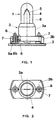
- contact pins 8 each with a support surface 8a on the circuit board 2 rests and is soldered onto a conductor track.
- the tub-like base 14 is with two continuous, to both of the pinch 12a arranged holes Mistake.
- a metallic sleeve 16 is arranged in each of these bores, which are each welded to one of the power supply lines 13 and form the electrical contacts of the base 14 or the small incandescent lamp 11.
- the metallic sleeves 16 each hold a metallic one Contact pin 17, which are part of the socket and with the sleeves 16th enter into a detachable connector.
- the contact pins 17 each have a longitudinally extending gap 17b, which during insertion the contact pins 17 narrowed into the metallic sleeves 16 so that the contact pins 17 are arranged with a clamp fit in the metallic sleeves 16.
- the contact pins 17 are each provided with a contact surface 17a rests on the printed circuit board 14 and is soldered onto a conductor track. To establish the plug connection between the base contacts 16 and the contact pins 17 to facilitate the contact surface 17a opposite free ends of the contact pins 17 are sharpened.
Landscapes
- Fastening Of Light Sources Or Lamp Holders (AREA)
- Connecting Device With Holders (AREA)
- Coupling Device And Connection With Printed Circuit (AREA)
- Non-Portable Lighting Devices Or Systems Thereof (AREA)
- Arrangement Of Elements, Cooling, Sealing, Or The Like Of Lighting Devices (AREA)
- Details Of Connecting Devices For Male And Female Coupling (AREA)
Claims (8)
- Platine à circuit imprimé comportant une douille et un culot pour une petite lampe à incandescence, le culot (3 ; 14) étant muni de contacts (7 ; 16) électriques qui servent à alimenter en tension la petite lampe (1 ; 11) à incandescence, caractérisée en ce que les contacts (7 ; 16) électriques du culot sont réalisés en manchons métalliques et en ce que la douille comporte des broches (8 ; 17) de contact métalliques, qui sont fixées de manière inamovible à la platine (2 ; 10) à circuit imprimé et qui forment avec les contacts (7 ; 16) de culot réalisés en manchons métalliques une liaison par enfichage amovible.
- Platine à circuit imprimé suivant la revendication 1, caractérisée en ce que les broches (8 ; 17) de contact comportent chacune un interstice (8b ; 17b) qui se rétrécit lors de l'introduction des broches (8 ; 17) de contact dans les manchons (7 ; 16) métalliques, si bien que les broches (8 ; 17) de contact sont montées en ajustement serré dans les manchons (7 ; 16) métalliques.
- Platine à circuit imprimé suivant la revendication 1, caractérisée en ce que les broches (8 ; 17) de contact sont brasées aux pistes conductrices de la platine (2 ; 10) à circuit imprimé.
- Platine à circuit imprimé suivant la revendication 1, caractérisée en ce que les manchons (7; 16) métalliques sont reliés de manière conductrice de l'électricité à des entrées (6 ; 13) de courant qui sont sorties de l'ampoule (4 ; 12) de la petite lampe (1 ; 11) à incandescence.
- Platine à circuit imprimé suivant la revendication 1, caractérisée en ce que le culot a un dispositif de réception pour l'ampoule (4 ; 12) de la petite lampe (1 ; 11) à incandescence.
- Platine à circuit imprimé suivant la revendication 1, caractérisée en ce que la douille est constituée de la platine (2 ; 10) à circuit imprimé et des broches (8 ; 17) de contact.
- Procédé pour monter une platine à circuit imprimé à douille et culot pour une petite lampe à incandescence comportant les dispositions de la revendication 1, caractérisé en ce que, pour équiper pour la première fois la platine (2 ; 10) à circuit imprimé, on enfiche les broches (8 ; 17) de contact de la douille dans les contacts de culot, réalisés en manchons (7 ; 16) métalliques, de la petite lampe (1 ; 11) à incandescence préfabriquée et en ce que lorsqu'on équipe la platine à circuit imprimé pour la première fois, on fixe ses broches (8 ; 17) de contact de manière inamovible à la platine (2 ; 10) à circuit imprimé, si bien que, lors du remplacement d'une petite lampe (1 ; 11) à incandescence montée sur la platine (2 ; 10) à circuit imprimé, la liaison d'enfichage existant entre les broches (8 ; 17) de contact et les manchons (7 ; 16) métalliques est détachée et les broches (8 ; 17) de contact restent pour enfiler une lampe de remplacement sur la platine (2 ; 10) à circuit imprimé.
- Procédé suivant la revendication 7, caractérisé en ce que l'on brase les broches (8 ; 17) de contact à la platine (2 ; 10) à circuit imprimé lorsqu'on l'équipe pour la première fois.
Applications Claiming Priority (3)
| Application Number | Priority Date | Filing Date | Title |
|---|---|---|---|
| DE19624690A DE19624690A1 (de) | 1996-06-20 | 1996-06-20 | Fassung und Sockel für eine Kleinglühlampe |
| DE19624690 | 1996-06-20 | ||
| PCT/DE1997/001121 WO1997049148A2 (fr) | 1996-06-20 | 1997-06-04 | Douille et culot pour petite lampe a incandescence |
Publications (2)
| Publication Number | Publication Date |
|---|---|
| EP0906645A2 EP0906645A2 (fr) | 1999-04-07 |
| EP0906645B1 true EP0906645B1 (fr) | 2000-03-22 |
Family
ID=7797519
Family Applications (1)
| Application Number | Title | Priority Date | Filing Date |
|---|---|---|---|
| EP97925898A Expired - Lifetime EP0906645B1 (fr) | 1996-06-20 | 1997-06-04 | Platine à circuit imprimé avec douille et culot pour petite lampe à incandence |
Country Status (11)
| Country | Link |
|---|---|
| EP (1) | EP0906645B1 (fr) |
| JP (1) | JP2001515644A (fr) |
| KR (1) | KR20000016776A (fr) |
| CN (1) | CN1096136C (fr) |
| AT (1) | ATE191105T1 (fr) |
| BR (1) | BR9709849A (fr) |
| DE (2) | DE19624690A1 (fr) |
| ES (1) | ES2144316T3 (fr) |
| HU (1) | HUP0103012A3 (fr) |
| TW (1) | TW371811B (fr) |
| WO (1) | WO1997049148A2 (fr) |
Families Citing this family (1)
| Publication number | Priority date | Publication date | Assignee | Title |
|---|---|---|---|---|
| KR20190006807A (ko) | 2017-07-11 | 2019-01-21 | 유성옥 | 물고기 포획용 통발 |
Family Cites Families (4)
| Publication number | Priority date | Publication date | Assignee | Title |
|---|---|---|---|---|
| GB1053039A (fr) * | ||||
| DE3147514A1 (de) * | 1981-12-01 | 1983-06-09 | Ulo-Werk Moritz Ullmann Gmbh & Co Kg, 7340 Geislingen | Lampentraeger fuer kraftfahrzeuge |
| DE4017131C1 (fr) * | 1990-05-28 | 1991-11-07 | Albrecht, Paul, 8600 Bamberg, De | |
| DE4401487C2 (de) * | 1994-01-21 | 1997-08-14 | Albrecht Paul | Fassung für Kleinglühlampe |
-
1996
- 1996-06-20 DE DE19624690A patent/DE19624690A1/de not_active Withdrawn
-
1997
- 1997-05-20 TW TW086106737A patent/TW371811B/zh active
- 1997-06-04 HU HU0103012A patent/HUP0103012A3/hu unknown
- 1997-06-04 JP JP50205798A patent/JP2001515644A/ja active Pending
- 1997-06-04 AT AT97925898T patent/ATE191105T1/de not_active IP Right Cessation
- 1997-06-04 DE DE59701323T patent/DE59701323D1/de not_active Expired - Fee Related
- 1997-06-04 EP EP97925898A patent/EP0906645B1/fr not_active Expired - Lifetime
- 1997-06-04 WO PCT/DE1997/001121 patent/WO1997049148A2/fr not_active Ceased
- 1997-06-04 BR BR9709849A patent/BR9709849A/pt not_active IP Right Cessation
- 1997-06-04 KR KR1019980710385A patent/KR20000016776A/ko not_active Ceased
- 1997-06-04 CN CN97193952A patent/CN1096136C/zh not_active Expired - Fee Related
- 1997-06-04 ES ES97925898T patent/ES2144316T3/es not_active Expired - Lifetime
Also Published As
| Publication number | Publication date |
|---|---|
| ES2144316T3 (es) | 2000-06-01 |
| BR9709849A (pt) | 1999-08-10 |
| KR20000016776A (ko) | 2000-03-25 |
| EP0906645A2 (fr) | 1999-04-07 |
| WO1997049148A3 (fr) | 2001-03-08 |
| DE19624690A1 (de) | 1998-01-02 |
| DE59701323D1 (de) | 2000-04-27 |
| WO1997049148A2 (fr) | 1997-12-24 |
| JP2001515644A (ja) | 2001-09-18 |
| HUP0103012A2 (hu) | 2001-12-28 |
| HUP0103012A3 (en) | 2003-06-30 |
| CN1096136C (zh) | 2002-12-11 |
| TW371811B (en) | 1999-10-11 |
| CN1216640A (zh) | 1999-05-12 |
| ATE191105T1 (de) | 2000-04-15 |
Similar Documents
| Publication | Publication Date | Title |
|---|---|---|
| EP0452743A1 (fr) | Lampe à décharge compacte à basse pression | |
| DE1941836B2 (de) | An eine gedruckte Schaltung angeschlossene Fassung für Glühlampen | |
| DE2441318C2 (de) | Sicherheitsvorrichtung für elektrische Verbindungsvorrichtungen | |
| WO1981001082A1 (fr) | Dispositif de couplage electrique | |
| DE68912002T2 (de) | Elektrische Lampe. | |
| DE3439171A1 (de) | Einseitig gesockelte quecksilberdampfniederdruckentladungslampe | |
| DE68908780T2 (de) | Elektrische Lampe. | |
| EP0179473A2 (fr) | Adaptateur pour une lampe à décharge à basse pression à culot unique | |
| DE69211726T2 (de) | Gesockelte elektrische Lampe für Netzspannungsbetrieb | |
| EP0854497B1 (fr) | Lampe compacte à décharge basse pression | |
| EP0906645B1 (fr) | Platine à circuit imprimé avec douille et culot pour petite lampe à incandence | |
| EP1255273A2 (fr) | Lampe électrique | |
| DE3014490C2 (de) | Elektrischer Schalter mit Beleuchtungseinrichtung | |
| EP0909467B1 (fr) | Petite lampe a incandescence et support pour une telle lampe | |
| DE2245365C3 (de) | Geteilter Sockel für eine ringförmige Leuchtstofflampe | |
| DE69000386T2 (de) | Sichereitszusammenbau eines verbinders und einer hochspannungslampe, besonders fuer wagenbeleuchtung. | |
| DE8430109U1 (de) | Kontaktelement | |
| DE202004014617U1 (de) | Adapter für ein Lampenbetriebsgerät | |
| EP0151674A2 (fr) | Lampe d'intérieur et/ou de travail | |
| DE69703453T2 (de) | Vorrichtung zur herstellung eines kontakts mit einem sockelteil,insbesondere einer gasentladungslampe | |
| DE460984C (de) | Aus Fassungsbock und abnehmbarem Deckel bestehende Fassung fuer elektrische, mit Metallsockeln versehene Roehrenlampen, sogenannte Soffittenlampen | |
| DE3818019C2 (de) | Leuchte | |
| DE4405760A1 (de) | Leuchtmittel sowie beleuchtbarer elektrischer Schalter | |
| DE838032C (de) | Stromzuführungsfassungen für Beleuchtungskörper mit Leuchtröhre | |
| EP0829902A2 (fr) | Lampe électrique |
Legal Events
| Date | Code | Title | Description |
|---|---|---|---|
| PUAI | Public reference made under article 153(3) epc to a published international application that has entered the european phase |
Free format text: ORIGINAL CODE: 0009012 |
|
| 17P | Request for examination filed |
Effective date: 19981204 |
|
| AK | Designated contracting states |
Kind code of ref document: A2 Designated state(s): AT BE DE ES FR GB IT NL SE |
|
| RTI1 | Title (correction) |
Free format text: CIRCUIT PLATE WITH SOCKET AND BASE FOR A SMALL INCANDESCENT LAMP |
|
| GRAG | Despatch of communication of intention to grant |
Free format text: ORIGINAL CODE: EPIDOS AGRA |
|
| RTI1 | Title (correction) |
Free format text: PRINTED CIRCUIT BOARD WITH SOCKET AND BASE FOR A SMALL INCANDESCENT LAMP |
|
| 17Q | First examination report despatched |
Effective date: 19990630 |
|
| GRAG | Despatch of communication of intention to grant |
Free format text: ORIGINAL CODE: EPIDOS AGRA |
|
| GRAH | Despatch of communication of intention to grant a patent |
Free format text: ORIGINAL CODE: EPIDOS IGRA |
|
| GRAH | Despatch of communication of intention to grant a patent |
Free format text: ORIGINAL CODE: EPIDOS IGRA |
|
| GRAA | (expected) grant |
Free format text: ORIGINAL CODE: 0009210 |
|
| AK | Designated contracting states |
Kind code of ref document: B1 Designated state(s): AT BE DE ES FR GB IT NL SE |
|
| REF | Corresponds to: |
Ref document number: 191105 Country of ref document: AT Date of ref document: 20000415 Kind code of ref document: T |
|
| REF | Corresponds to: |
Ref document number: 59701323 Country of ref document: DE Date of ref document: 20000427 |
|
| REG | Reference to a national code |
Ref country code: ES Ref legal event code: FG2A Ref document number: 2144316 Country of ref document: ES Kind code of ref document: T3 |
|
| ITF | It: translation for a ep patent filed | ||
| GBT | Gb: translation of ep patent filed (gb section 77(6)(a)/1977) |
Effective date: 20000524 |
|
| ET | Fr: translation filed | ||
| PLBE | No opposition filed within time limit |
Free format text: ORIGINAL CODE: 0009261 |
|
| STAA | Information on the status of an ep patent application or granted ep patent |
Free format text: STATUS: NO OPPOSITION FILED WITHIN TIME LIMIT |
|
| 26N | No opposition filed | ||
| REG | Reference to a national code |
Ref country code: GB Ref legal event code: IF02 |
|
| PGFP | Annual fee paid to national office [announced via postgrant information from national office to epo] |
Ref country code: AT Payment date: 20020529 Year of fee payment: 6 |
|
| PGFP | Annual fee paid to national office [announced via postgrant information from national office to epo] |
Ref country code: SE Payment date: 20020606 Year of fee payment: 6 |
|
| PGFP | Annual fee paid to national office [announced via postgrant information from national office to epo] |
Ref country code: GB Payment date: 20020610 Year of fee payment: 6 |
|
| PGFP | Annual fee paid to national office [announced via postgrant information from national office to epo] |
Ref country code: NL Payment date: 20020620 Year of fee payment: 6 |
|
| PGFP | Annual fee paid to national office [announced via postgrant information from national office to epo] |
Ref country code: FR Payment date: 20020625 Year of fee payment: 6 Ref country code: BE Payment date: 20020625 Year of fee payment: 6 |
|
| PGFP | Annual fee paid to national office [announced via postgrant information from national office to epo] |
Ref country code: ES Payment date: 20020626 Year of fee payment: 6 |
|
| PGFP | Annual fee paid to national office [announced via postgrant information from national office to epo] |
Ref country code: DE Payment date: 20020819 Year of fee payment: 6 |
|
| PG25 | Lapsed in a contracting state [announced via postgrant information from national office to epo] |
Ref country code: GB Free format text: LAPSE BECAUSE OF NON-PAYMENT OF DUE FEES Effective date: 20030604 Ref country code: AT Free format text: LAPSE BECAUSE OF NON-PAYMENT OF DUE FEES Effective date: 20030604 |
|
| PG25 | Lapsed in a contracting state [announced via postgrant information from national office to epo] |
Ref country code: SE Free format text: LAPSE BECAUSE OF NON-PAYMENT OF DUE FEES Effective date: 20030605 Ref country code: ES Free format text: LAPSE BECAUSE OF NON-PAYMENT OF DUE FEES Effective date: 20030605 |
|
| PG25 | Lapsed in a contracting state [announced via postgrant information from national office to epo] |
Ref country code: BE Free format text: LAPSE BECAUSE OF NON-PAYMENT OF DUE FEES Effective date: 20030630 |
|
| BERE | Be: lapsed |
Owner name: *PATENT-TREUHAND-G. -FUR ELEKTRISCHE GLUHLAMPEN M. Effective date: 20030630 |
|
| PG25 | Lapsed in a contracting state [announced via postgrant information from national office to epo] |
Ref country code: NL Free format text: LAPSE BECAUSE OF NON-PAYMENT OF DUE FEES Effective date: 20040101 Ref country code: DE Free format text: LAPSE BECAUSE OF NON-PAYMENT OF DUE FEES Effective date: 20040101 |
|
| GBPC | Gb: european patent ceased through non-payment of renewal fee |
Effective date: 20030604 |
|
| EUG | Se: european patent has lapsed | ||
| PG25 | Lapsed in a contracting state [announced via postgrant information from national office to epo] |
Ref country code: FR Free format text: LAPSE BECAUSE OF NON-PAYMENT OF DUE FEES Effective date: 20040227 |
|
| NLV4 | Nl: lapsed or anulled due to non-payment of the annual fee |
Effective date: 20040101 |
|
| REG | Reference to a national code |
Ref country code: FR Ref legal event code: ST |
|
| REG | Reference to a national code |
Ref country code: ES Ref legal event code: FD2A Effective date: 20030605 |
|
| PG25 | Lapsed in a contracting state [announced via postgrant information from national office to epo] |
Ref country code: IT Free format text: LAPSE BECAUSE OF NON-PAYMENT OF DUE FEES;WARNING: LAPSES OF ITALIAN PATENTS WITH EFFECTIVE DATE BEFORE 2007 MAY HAVE OCCURRED AT ANY TIME BEFORE 2007. THE CORRECT EFFECTIVE DATE MAY BE DIFFERENT FROM THE ONE RECORDED. Effective date: 20050604 |