EP1255273A2 - Lampe électrique - Google Patents
Lampe électrique Download PDFInfo
- Publication number
- EP1255273A2 EP1255273A2 EP02004560A EP02004560A EP1255273A2 EP 1255273 A2 EP1255273 A2 EP 1255273A2 EP 02004560 A EP02004560 A EP 02004560A EP 02004560 A EP02004560 A EP 02004560A EP 1255273 A2 EP1255273 A2 EP 1255273A2
- Authority
- EP
- European Patent Office
- Prior art keywords
- lamp
- metal part
- contact pin
- lamp vessel
- hollow contact
- Prior art date
- Legal status (The legal status is an assumption and is not a legal conclusion. Google has not performed a legal analysis and makes no representation as to the accuracy of the status listed.)
- Withdrawn
Links
- 239000002184 metal Substances 0.000 claims abstract description 54
- 229910052751 metal Inorganic materials 0.000 claims abstract description 54
- 238000004519 manufacturing process Methods 0.000 claims abstract description 5
- 239000011324 bead Substances 0.000 claims description 5
- 238000000034 method Methods 0.000 claims description 5
- 238000009411 base construction Methods 0.000 description 3
- 238000004873 anchoring Methods 0.000 description 2
- 230000001419 dependent effect Effects 0.000 description 1
- 239000011521 glass Substances 0.000 description 1
- 238000002347 injection Methods 0.000 description 1
- 239000007924 injection Substances 0.000 description 1
- 238000001746 injection moulding Methods 0.000 description 1
- MOFOBJHOKRNACT-UHFFFAOYSA-N nickel silver Chemical compound [Ni].[Ag] MOFOBJHOKRNACT-UHFFFAOYSA-N 0.000 description 1
- 239000010956 nickel silver Substances 0.000 description 1
- 239000010935 stainless steel Substances 0.000 description 1
- 229910001220 stainless steel Inorganic materials 0.000 description 1
Images


Classifications
-
- H—ELECTRICITY
- H01—ELECTRIC ELEMENTS
- H01J—ELECTRIC DISCHARGE TUBES OR DISCHARGE LAMPS
- H01J9/00—Apparatus or processes specially adapted for the manufacture, installation, removal, maintenance of electric discharge tubes, discharge lamps, or parts thereof; Recovery of material from discharge tubes or lamps
- H01J9/24—Manufacture or joining of vessels, leading-in conductors or bases
- H01J9/34—Joining base to vessel
-
- H—ELECTRICITY
- H01—ELECTRIC ELEMENTS
- H01K—ELECTRIC INCANDESCENT LAMPS
- H01K1/00—Details
- H01K1/42—Means forming part of the lamp for the purpose of providing electrical connection, or support for, the lamp
- H01K1/46—Means forming part of the lamp for the purpose of providing electrical connection, or support for, the lamp supported by a separate part, e.g. base, cap
-
- H—ELECTRICITY
- H01—ELECTRIC ELEMENTS
- H01K—ELECTRIC INCANDESCENT LAMPS
- H01K3/00—Apparatus or processes adapted to the manufacture, installing, removal, or maintenance of incandescent lamps or parts thereof
- H01K3/16—Joining of caps to vessel
Definitions
- the invention relates to an electric lamp according to the preamble of the claim 1.
- Such an electric lamp is for example in the European patent EP 0 815 578 B1.
- This patent describes a motor vehicle headlight lamp, which is a lamp vessel with a filament arranged therein, Has power supplies for the filament and a lamp base, the Lamp base has a metal ring for holding the lamp vessel and an electrical one Connections provided plastic part.
- a motor vehicle auxiliary light lamp such as a brake light lamp or a flashing light lamp
- a motor vehicle auxiliary light lamp does not have such high requirements Alignment of the lamp - filament or discharge arc - with respect to the Reflector placed like a motor vehicle headlight lamp.
- the base construction for an auxiliary light lamp can therefore be simplified accordingly.
- the base of the electric lamp according to the invention has an annular, resilient metal part for holding the lamp vessel and one with electrical Connections provided plastic part, the lamp vessel with the Metal part forms a plug connection and / or the metal part with the plastic part forms a connector.
- At least one electrical connection is hollow Contact pin formed in which one end protrudes from the lamp vessel and for supplying energy to at least one light source is arranged and fixed. Due to the resilient design of the metal part can be done by exerting pressure on the plug connection or the plug connections a mechanical stress can be generated in the metal part and by fixing the Power can be maintained in the hollow contact pin.
- the whole So base construction is through the connection of power supply and hollow Contact pin in a play-free arrangement and clamp fit held together. There are no further components are required to base the lamp according to the invention.
- the metal part is advantageously provided with several molded guide ridges and depth stops.
- the spring action the metal part can be advantageous and easily using the depth stops produce.
- the connector between the metal part and the plastic part is advantageously generated by means of several tabs on the metal part are molded and into appropriate slots or recesses in the plastic part are insertable.
- the contact pin is advantageously cylindrical and has one its outer diameter enlarging bead and a funnel-shaped expanded Section on.
- the funnel-shaped section also serves as a threading aid for the end of the power supply arranged in the hollow contact pin.
- the mechanical tension is simple and advantageous made by means of several depth stops for the lamp vessel, which to the Metal part are molded.
- the metal part points to the production of the plug connection with the plastic part advantageously several molded tabs, which in suitable recesses of the plastic part are introduced. advantageously, will come to an end before the plug connection or plug connections are made of the hollow contact pin funnel-shaped to thread the power supply in the hollow contact pin and to securely anchor the To ensure contact pin in the plastic part.
- Lamp is an incandescent lamp with an electrical power consumption of approx. 19 W and a nominal voltage of 12 V.
- This lamp is for use provided in a motor vehicle as a brake light or flashing light.
- Figure 1 shows a schematic representation of this light bulb.
- the incandescent lamp has a gas-tight closure by means of a pinch foot 11 Lamp holder 1 made of glass.
- a filament 2 is arranged in the axial direction.
- the ends of the Filament 2 are each electrically conductive with a power supply wire 3, 4 connected.
- the power supply wires 3, 4, which are used to supply energy to the filament 2 serve, are led out of the lamp vessel 1 via the squeezing foot 11.
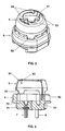
- the base of the lamp consists of an annular metal part 5 and one Plastic part 6, both of which are connected to one another by a plug connection.
- the pinch foot 11 of the lamp vessel 1 is in the metal part 5 by means of a plug connection supported.
- the guide webs molded onto the metal part 5 serve this purpose 51, which abut the narrow end faces of the pinch foot 11, and which the metal part 5 molded, resilient depth stops 53, on the one hand rest on the wide sides of the pinch foot 11 and on the other hand one vertically to the lamp vessel axis arranged support surface for the hollow, opposite form the squeeze foot 11 expanded part of the lamp vessel 1.
- the boardwalks 51 and the depth stops 53 support the pinch foot 11 of the lamp vessel on all sides from, but without a press fit of the pinch foot 11 in the annular metal part 5 to generate.
- the plastic part 6 is equipped with the electrical connections 7, 8 of the lamp.
- the electrical connections 7, 8 are both designed as hollow contact pins.
- the free ends of the two power supply wires 3, 4 are each in one of the hollow contact pins 7 and 8 arranged and there with the contact pins 7 and 8 welded. Details of the base construction are shown in Figures 2 to 6.
- the annular metal part 5 has four equidistantly arranged along its circumference Tabs 52.
- the tabs 52 each engage in suitably matched Slots 61 in the plastic part 6.
- Form the tabs 52 and the slots 61 the plug connection between the metal part 5 and the plastic part 6 of the lamp base.
- the metal part 5 is resilient.
- the plastic part 6 has two Breakthroughs 9, 10 in which a hollow contact pin 7 or 8 is anchored is.
- the hollow contact pins serve as electrical connections for the lamp.
- the contact pins 7, 8 each have a bead 71 that increases their outer diameter and a funnel-shaped section 72.
- the bead 71 and the funnel-shaped Section 72 ensures secure anchoring of the respective contact pin 7, 8 in the openings 9, 10.
- the openings 9, 10 each have a stop 91 for the bead 71 and a funnel-like area 92, 102 for the funnel-shaped section 72 of the corresponding contact pin 7 or 8.
- the two power supplies 3, 4 each extend into one of the hollow Contact pins 7 and 8.
- the funnel-shaped section 72 of the corresponding contact pin 7 or 8 serves as a threading aid for the end of the power supply 3 or 4.
- the metal part 5 is made of stainless steel or nickel silver and the plastic part 6 is designed as an injection molded part.
- the prefabricated lamp vessel 1 including the one in it assembled filament 2 and the power supplies 3, 4, the prefabricated metal part 5 and the prefabricated plastic part 6 assembled, that is, by Plug connections assembled together.
- the metal part 5, of the lamp vessel 1 and the plastic part 6 are the free ends of the power supplies 3, 4 inserted into the hollow contact pins 9, 10. Then it turns on the connectors exerted pressure in the axial direction, so that in the metal part 5 and in particular in the depth stops 53 generates a mechanical tension becomes.
- the metal part 5 or the depth stops 53 under mechanical Voltage is the ends of the arranged in the hollow contact pins 8, 9 Power leads 3, 4 welded to the contact pins 9, 10.
- both electrical connections do not have to be considered hollow contact pins can be formed. It is sufficient that at least one electrical connection is designed as a hollow contact pin.
- the guide webs 51 can also be designed such that they are clamping or bear resiliently on the pinch foot 11 of the lamp vessel 1.
- this Case is primarily the connector between the metal part 5 and the Plastic part 6 through the weld connection of the power supply lines with the contact pins with metal part 5 under mechanical tension, free of play and permanently fixed.
Landscapes
- Engineering & Computer Science (AREA)
- Manufacturing & Machinery (AREA)
- Non-Portable Lighting Devices Or Systems Thereof (AREA)
- Common Detailed Techniques For Electron Tubes Or Discharge Tubes (AREA)
Applications Claiming Priority (2)
| Application Number | Priority Date | Filing Date | Title |
|---|---|---|---|
| DE10121608 | 2001-05-04 | ||
| DE10121608A DE10121608A1 (de) | 2001-05-04 | 2001-05-04 | Elektrische Lampe |
Publications (2)
| Publication Number | Publication Date |
|---|---|
| EP1255273A2 true EP1255273A2 (fr) | 2002-11-06 |
| EP1255273A3 EP1255273A3 (fr) | 2006-02-15 |
Family
ID=7683552
Family Applications (1)
| Application Number | Title | Priority Date | Filing Date |
|---|---|---|---|
| EP02004560A Withdrawn EP1255273A3 (fr) | 2001-05-04 | 2002-02-27 | Lampe électrique |
Country Status (5)
| Country | Link |
|---|---|
| US (1) | US6628081B2 (fr) |
| EP (1) | EP1255273A3 (fr) |
| JP (1) | JP2002343309A (fr) |
| CA (1) | CA2384484A1 (fr) |
| DE (1) | DE10121608A1 (fr) |
Cited By (1)
| Publication number | Priority date | Publication date | Assignee | Title |
|---|---|---|---|---|
| EP1729326A3 (fr) * | 2005-05-24 | 2007-11-14 | Patent-Treuhand-Gesellschaft für elektrische Glühlampen mbH | Culot de lampe et lampe |
Families Citing this family (10)
| Publication number | Priority date | Publication date | Assignee | Title |
|---|---|---|---|---|
| DE20300699U1 (de) * | 2003-01-16 | 2003-03-20 | Patent-Treuhand-Gesellschaft für elektrische Glühlampen mbH, 81543 München | Lampensockel und Lampe mit einem Lampensockel |
| JP2007520855A (ja) * | 2003-10-30 | 2007-07-26 | コーニンクレッカ フィリップス エレクトロニクス エヌ ヴィ | キー機能付口金を具えるランプ及びかかるランプを製造する方法 |
| JP4253573B2 (ja) * | 2003-12-09 | 2009-04-15 | ハリソン東芝ライティング株式会社 | 電球の製造方法 |
| DE102004007150A1 (de) * | 2004-02-12 | 2005-08-25 | Patent-Treuhand-Gesellschaft für elektrische Glühlampen mbH | Sockel für eine Scheinwerferlampe und Scheinwerferlampe |
| US20060114695A1 (en) * | 2004-12-01 | 2006-06-01 | L&C Lighting Technology Corp. | Bulb holder with an insulator plate for avoiding electric short of the bulb |
| US7494262B2 (en) * | 2007-05-04 | 2009-02-24 | Honeywell International Inc. | Halogen burner and receptacle assembly |
| WO2009107060A1 (fr) * | 2008-02-29 | 2009-09-03 | Koninklijke Philips Electronics N.V. | Culot de lampe et son procédé de fabrication |
| JP5535195B2 (ja) * | 2008-04-25 | 2014-07-02 | コーニンクレッカ フィリップス エヌ ヴェ | ランプ、及びランプを製造する方法 |
| US8896205B1 (en) * | 2013-10-18 | 2014-11-25 | Amc Automation Co., Ltd. | Quartz light |
| CN107023811B (zh) * | 2016-02-01 | 2023-06-30 | 厦门广泓工贸有限公司 | 一种灯头电连接器及应用此电连接器的灯管或灯泡 |
Family Cites Families (12)
| Publication number | Priority date | Publication date | Assignee | Title |
|---|---|---|---|---|
| DE815578C (de) | 1949-01-01 | 1951-10-04 | Otto Bongers | Gewaechshaus |
| DE2966250D1 (en) * | 1978-05-17 | 1983-11-10 | Emi Plc Thorn | Cap assemblies for lamps |
| JPS5711453A (en) * | 1980-06-23 | 1982-01-21 | Mitsubishi Electric Corp | Manufacture of tube bulb |
| DE3743612A1 (de) * | 1987-12-22 | 1989-07-06 | Patent Treuhand Ges Fuer Elektrische Gluehlampen Mbh | Hochdruckentladungslampe |
| DE59005400D1 (de) * | 1989-02-24 | 1994-05-26 | Patent Treuhand Ges Fuer Elektrische Gluehlampen Mbh | Kittlos gesockelte elektrische Lampe. |
| US5239226A (en) * | 1990-12-14 | 1993-08-24 | General Electric Company | Replaceable lamp assembly for automotive headlamps |
| DE4223643A1 (de) * | 1992-07-17 | 1994-01-20 | Patent Treuhand Ges Fuer Elektrische Gluehlampen Mbh | Einseitig gesockelte Hochdruckentladungslampe |
| DE19548521A1 (de) * | 1995-12-22 | 1997-06-26 | Patent Treuhand Ges Fuer Elektrische Gluehlampen Mbh | Lampen-Reflektor-Einheit |
| CA2215068C (fr) | 1996-01-11 | 2004-12-28 | Patent-Treuhand-Gesellschaft Fuer Elektrische Gluehlampen Mbh | Lampe electrique munie d'un culot sans ciment |
| DE19709928A1 (de) * | 1997-03-11 | 1998-09-17 | Patent Treuhand Ges Fuer Elektrische Gluehlampen Mbh | Halogenglühlampe und Fassung |
| JP4054464B2 (ja) * | 1998-11-26 | 2008-02-27 | フェニックス電機株式会社 | リフレクタ付きハロゲンランプ |
| DE19855265A1 (de) * | 1998-12-01 | 2000-06-21 | Patent Treuhand Ges Fuer Elektrische Gluehlampen Mbh | Elektrische Lampe und Beleuchtungsvorrichtung mit einer derartigen elektrischen Lampe |
-
2001
- 2001-05-04 DE DE10121608A patent/DE10121608A1/de not_active Withdrawn
-
2002
- 2002-02-27 EP EP02004560A patent/EP1255273A3/fr not_active Withdrawn
- 2002-04-30 JP JP2002127754A patent/JP2002343309A/ja not_active Abandoned
- 2002-05-02 CA CA002384484A patent/CA2384484A1/fr not_active Abandoned
- 2002-05-06 US US10/138,248 patent/US6628081B2/en not_active Expired - Fee Related
Cited By (1)
| Publication number | Priority date | Publication date | Assignee | Title |
|---|---|---|---|---|
| EP1729326A3 (fr) * | 2005-05-24 | 2007-11-14 | Patent-Treuhand-Gesellschaft für elektrische Glühlampen mbH | Culot de lampe et lampe |
Also Published As
| Publication number | Publication date |
|---|---|
| US6628081B2 (en) | 2003-09-30 |
| DE10121608A1 (de) | 2002-11-07 |
| US20020163288A1 (en) | 2002-11-07 |
| EP1255273A3 (fr) | 2006-02-15 |
| CA2384484A1 (fr) | 2002-11-04 |
| JP2002343309A (ja) | 2002-11-29 |
Similar Documents
| Publication | Publication Date | Title |
|---|---|---|
| EP1255273A2 (fr) | Lampe électrique | |
| DE102004011635A1 (de) | Fassung für zweiseitig gesockelte röhrenförmige Leuchtstofflampen mit Zweistift-Sockeln | |
| EP0854497B1 (fr) | Lampe compacte à décharge basse pression | |
| DE69118123T2 (de) | Signallampe und Verfahren zur Herstellung derselben | |
| DD212617A5 (de) | Lampenaufbau | |
| EP0923105B1 (fr) | Lampe à décharge à basse pression de type compact | |
| DE60034284T2 (de) | Lampe mit Schraubsockel und im Sockelgehäuse enthaltene Elektronik, sowie Verfahren zur deren Herstellung | |
| DE60037175T2 (de) | Niederdruck gasentladungslampe | |
| DE19509112A1 (de) | Kompaktleuchtstofflampe mit kreisrundem Gasentladungsgefäß | |
| DE2355637A1 (de) | Elektrische lampe und verfahren zu deren herstellung | |
| DE60021990T2 (de) | Elektrische lampe | |
| DE2245365C3 (de) | Geteilter Sockel für eine ringförmige Leuchtstofflampe | |
| EP1329931B1 (fr) | Lampe compacte à décharge à basse pression | |
| DE2018702A1 (de) | Mit einem Kunststoffsockel versehene elektrische Lampe | |
| DE2340671A1 (de) | Signaleinrichtung | |
| DE19805258C2 (de) | Lampenfassung | |
| EP0906645B1 (fr) | Platine à circuit imprimé avec douille et culot pour petite lampe à incandence | |
| DE19726230C2 (de) | Elektrisches Anschlußelement | |
| DE1789012C3 (de) | Kleinstglühlampe | |
| EP2084727B1 (fr) | Source électrique de lumière destinée en particulier pour utilisation dans un réflecteur | |
| DE2408560C3 (de) | Elektrische Lampe und Vorrichtung zu ihrer Herstellung | |
| DE9418257U1 (de) | Stabförmige elektrische Leuchte | |
| AT66090B (de) | Einrichtung zur Befestigung der Elektroden und Stromzuleitungen in den Fassungen für elektrische Glühlampen, Kontaktstöpsel und dgl. | |
| DE99413C (fr) | ||
| EP0012332B1 (fr) | Douille en matière isolante pour un support de lampe |
Legal Events
| Date | Code | Title | Description |
|---|---|---|---|
| PUAI | Public reference made under article 153(3) epc to a published international application that has entered the european phase |
Free format text: ORIGINAL CODE: 0009012 |
|
| AK | Designated contracting states |
Kind code of ref document: A2 Designated state(s): AT BE CH CY DE DK ES FI FR GB GR IE IT LI LU MC NL PT SE TR |
|
| AX | Request for extension of the european patent |
Free format text: AL;LT;LV;MK;RO;SI |
|
| PUAL | Search report despatched |
Free format text: ORIGINAL CODE: 0009013 |
|
| AK | Designated contracting states |
Kind code of ref document: A3 Designated state(s): AT BE CH CY DE DK ES FI FR GB GR IE IT LI LU MC NL PT SE TR |
|
| AX | Request for extension of the european patent |
Extension state: AL LT LV MK RO SI |
|
| RIC1 | Information provided on ipc code assigned before grant |
Ipc: H01K 1/46 20060101ALI20051228BHEP Ipc: H01J 5/62 20060101ALI20051228BHEP Ipc: H01J 5/58 20060101ALI20051228BHEP Ipc: H01J 5/56 20060101ALI20051228BHEP Ipc: H01J 5/54 20060101AFI20051228BHEP |
|
| 17P | Request for examination filed |
Effective date: 20060306 |
|
| AKX | Designation fees paid |
Designated state(s): AT BE CH CY DE DK ES FI FR GB GR IE IT LI LU MC NL PT SE TR |
|
| 17Q | First examination report despatched |
Effective date: 20060427 |
|
| STAA | Information on the status of an ep patent application or granted ep patent |
Free format text: STATUS: THE APPLICATION HAS BEEN WITHDRAWN |
|
| 18W | Application withdrawn |
Effective date: 20070920 |