EP0906843A1 - Tank - Google Patents
Tank Download PDFInfo
- Publication number
- EP0906843A1 EP0906843A1 EP98203172A EP98203172A EP0906843A1 EP 0906843 A1 EP0906843 A1 EP 0906843A1 EP 98203172 A EP98203172 A EP 98203172A EP 98203172 A EP98203172 A EP 98203172A EP 0906843 A1 EP0906843 A1 EP 0906843A1
- Authority
- EP
- European Patent Office
- Prior art keywords
- tank
- ribs
- protrusions
- tank according
- liquid
- Prior art date
- Legal status (The legal status is an assumption and is not a legal conclusion. Google has not performed a legal analysis and makes no representation as to the accuracy of the status listed.)
- Granted
Links
Images
Classifications
-
- B—PERFORMING OPERATIONS; TRANSPORTING
- B60—VEHICLES IN GENERAL
- B60K—ARRANGEMENT OR MOUNTING OF PROPULSION UNITS OR OF TRANSMISSIONS IN VEHICLES; ARRANGEMENT OR MOUNTING OF PLURAL DIVERSE PRIME-MOVERS IN VEHICLES; AUXILIARY DRIVES FOR VEHICLES; INSTRUMENTATION OR DASHBOARDS FOR VEHICLES; ARRANGEMENTS IN CONNECTION WITH COOLING, AIR INTAKE, GAS EXHAUST OR FUEL SUPPLY OF PROPULSION UNITS IN VEHICLES
- B60K15/00—Arrangement in connection with fuel supply of combustion engines or other fuel consuming energy converters, e.g. fuel cells; Mounting or construction of fuel tanks
- B60K15/03—Fuel tanks
- B60K15/03177—Fuel tanks made of non-metallic material, e.g. plastics, or of a combination of non-metallic and metallic material
Definitions
- the present invention relates to a particular type of material tank plastic intended to contain a liquid such as for example a fuel.
- the present invention aims to remedy this problem, and to provide a reservoir of plastic having undergone an internal surface treatment, which, while can be made of common plastics, has a high waterproofing and long-term durability.
- the present invention relates to a liquid reservoir essentially made of plastic, the inner surface of which has been surface treated in order to increase its impermeability to said liquid, characterized in that at least part of the interior surface of the tank is provided with protrusions capable of hindering the movement of the liquid.
- Such a tank has a high and lasting impermeability, in particular vis-à-vis fuels. This result is all the more surprising since the presence protuberances inevitably cause an increase in the area of the interior surface of the tank, as well as local thinning of its wall, and that we would therefore expect a deterioration in its impermeability.
- liquid tank any hollow body intended to contain liquid.
- the tank described above is very advantageous when used as a fuel tank.
- the tank according to the invention which can also, for example, serve as a container for any hydrocarbons, for solvents, etc.
- the tank according to the invention is advantageously used in motor vehicles.
- the plastic material includes one or more polymers, as well that possibly one or more usual additives such as stabilizers, antioxidants, pigments, lubricants, flame retardants, antistatic agents, load and / or reinforcement, etc.
- the polymer (s) used are generally thermoplastic polymers, and more particularly polyolefins.
- polymer it is preferred to use polyethylene (PE), in particular PE high density (HDPE).
- the tank may optionally include a or several other layers, based on one or more plastics identical or different.
- the wall of the tank consists of a single plastic material, i.e. it is a single-layer tank. This does not exclude the presence of usual accessories such as connections of filling pipes and / or connection to the engine, inserts, etc., made of possibly different materials.
- tank wall is made entirely of material thermoplastic
- a technique commonly used for its manufacture is extrusion blow molding. This technique is equally suitable for tanks monolayers than multilayers.
- Such a tank can also be manufactured by any other usual technique, for example by injection and welding, by rotational molding, etc.
- a fluorination treatment applied to a polyethylene tank we can obtain the formation of a fluorinated polyethylene layer whose thickness is typically a few microns or tenths of a micron.
- the invention provides very good results in case the interior surface of the tank has been treated by fluorination and / or by sulfonation.
- the protrusions can be of any type, for example studs or ribs, provided that they are capable of hindering the movement of the liquid to immediate proximity to the part of the interior surface of the tank that is provided. They can advantageously be in the form of ribs, which can in particular be rectilinear, polygonal and / or curved. Advantageously, the ribs delimit closed areas, for example hexagonal or rectangular areas, the center ("bottom") of which is thus lower than the top of the ribs. It is also advantageous that the protrusions are spaced substantially evenly. Very good results have obtained when the ribs are arranged in networks substantially perpendicular to substantially rectilinear ribs, parallel and equidistant, thus defining zones approximately rectangular.
- protrusions can help improve the mechanical strength of the tank (stiffening, etc.).
- exact geometry of the protrusions by example their radii of curvature in a plane perpendicular to the wall of the tank) must be chosen while respecting the constraints imposed by the process of manufacturing used.
- the height of the protrusions is generally of the order of a few millimeters. A height of at most 20 mm, and preferably at most 15 mm, gives good results. Furthermore, the height of the protrusions is advantageously at least 3 mm, and preferably at least 5 mm.
- the average width of the protrusions (measured at mid-height) is generally of the same order of magnitude as their height. It is however unnecessary to give the protrusions an excessive average width, which would have consequence of increasing the proportion of the area of the protrusions by compared to the total area of the interior surface of the tank, with the risk deterioration of its overall waterproofing.
- the average width of protrusions is usually fixed slightly beyond the minimum width imposed by the constraints linked to the manufacturing process used; so in the in most cases this average width will be at least twice the thickness of the tank wall.
- the average width of the protrusions is advantageously greater than 3 times the thickness of the wall of the tank, and preferably more than 4 times this thickness. In addition, average widths less than 6 times this thickness, and preferably less than 5 times this thickness, have given good results.
- the spacing between two neighboring ribs is generally of the order of a few tens of millimeters. It has proven advantageous that the spacing of the protrusions is at least 3 times their height, and preferably at least 4 times their height. Furthermore, this spacing is advantageously at most 9 times their height, and preferably at most 6 times their height. A spacing at least 20 mm, and in particular at least 35 mm, gives good results. Furthermore, the spacing is advantageously at most 100 mm, and preferably not more than 70 mm.
- the entire interior surface of the tank can be fitted with protuberances. Normally, however, erosion takes place mainly on the bottom wall of the tank, whether erosion due to movements of the liquid or any solid particles. Therefore, it is advantageous that minus the bottom wall of the interior surface of the tank is provided with protuberances. According to a particularly simple variant of this invention, only this bottom wall is provided with protuberances. (By wall means to designate the wall which forms the bottom of the tank when it is in its normal use position.)
- the protrusions can be produced by any suitable technique.
- prefabricated ribs in the form of a or several grids of a suitable material can be fixed on the surface inside the tank during or after its manufacture.
- the protrusions are an integral part of the tank wall.
- relief elements of shapes and dimensions suitable may be present on the surface of the mold used for manufacturing of the tank, in order to create protuberances in the wall of the tank during its manufacture by molding. These raised elements can be an integral part of the mold, or having been subsequently fixed to a preexisting conventional mold. This variant is advantageous insofar as it allows the reuse of existing molds with minor modifications. We can still use a mold provided with movable elements in relief (retractable), which one causes the displacement at a given point in the manufacturing process.
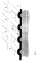
- FIG. 1 illustrates more precisely the manufacture of a reservoir in accordance with the invention. It represents, in section and in perspective, a metal mold (1), provided with ribs (2) with a profile devoid of sharp edges, used for molding a tank whose wall (3) is made of thermoplastic material.
- the ribs (2) of the mold cause similar ribs (4) to form on the inner surface of the tank.
- the mold has two networks perpendicular to ribs parallel to each other, which allows to form also, on the inner surface of the reservoir, perpendicular networks of ribs (4, 5) defining closed rectangular areas (6) lowered by relationship to the top of the ribs (4).
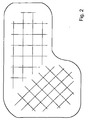
- Figure 2 schematically shows the bottom wall of a tank to fuel according to the invention.
- FIG. 2 schematically shows the bottom wall of a tank to fuel according to the invention.
Landscapes
- Engineering & Computer Science (AREA)
- Sustainable Development (AREA)
- Sustainable Energy (AREA)
- Chemical & Material Sciences (AREA)
- Combustion & Propulsion (AREA)
- Transportation (AREA)
- Mechanical Engineering (AREA)
- Life Sciences & Earth Sciences (AREA)
- Details Of Rigid Or Semi-Rigid Containers (AREA)
- Cooling, Air Intake And Gas Exhaust, And Fuel Tank Arrangements In Propulsion Units (AREA)
- Containers Having Bodies Formed In One Piece (AREA)
- Devices For Use In Laboratory Experiments (AREA)
- Pens And Brushes (AREA)
- Sampling And Sample Adjustment (AREA)
- Closures For Containers (AREA)
- Coating Apparatus (AREA)
Applications Claiming Priority (2)
| Application Number | Priority Date | Filing Date | Title |
|---|---|---|---|
| BE9700800 | 1997-10-03 | ||
| BE9700800A BE1011483A3 (fr) | 1997-10-03 | 1997-10-03 | Reservoir. |
Publications (2)
| Publication Number | Publication Date |
|---|---|
| EP0906843A1 true EP0906843A1 (de) | 1999-04-07 |
| EP0906843B1 EP0906843B1 (de) | 2002-09-04 |
Family
ID=3890761
Family Applications (1)
| Application Number | Title | Priority Date | Filing Date |
|---|---|---|---|
| EP19980203172 Expired - Lifetime EP0906843B1 (de) | 1997-10-03 | 1998-09-21 | Tank |
Country Status (5)
| Country | Link |
|---|---|
| EP (1) | EP0906843B1 (de) |
| AR (1) | AR017289A1 (de) |
| BE (1) | BE1011483A3 (de) |
| BR (1) | BR9803868A (de) |
| DE (1) | DE69807614T2 (de) |
Cited By (1)
| Publication number | Priority date | Publication date | Assignee | Title |
|---|---|---|---|---|
| US20220371433A1 (en) * | 2019-09-20 | 2022-11-24 | Kautex Textron Gmbh & Co. Kg | Plastic tank for motor vehicles having at least one reinforcing structure |
Citations (3)
| Publication number | Priority date | Publication date | Assignee | Title |
|---|---|---|---|---|
| DE3641356C1 (de) * | 1986-12-03 | 1988-07-07 | Daimler Benz Ag | Kraftstoffbehaelter fuer Fahrzeuge |
| US5213734A (en) | 1991-02-20 | 1993-05-25 | Solvay S.A. | Process for producing, by blow moulding, hollow bodies made of thermoplastic material having an improved impermeability to gases |
| EP0695779A1 (de) | 1994-07-20 | 1996-02-07 | SOLVAY (Société Anonyme) | Verfahren zur Oberflächenbehandlung eines Gegenständes durch Sulfonierung und Neutralisation |
-
1997
- 1997-10-03 BE BE9700800A patent/BE1011483A3/fr not_active IP Right Cessation
-
1998
- 1998-09-21 EP EP19980203172 patent/EP0906843B1/de not_active Expired - Lifetime
- 1998-09-21 DE DE1998607614 patent/DE69807614T2/de not_active Expired - Fee Related
- 1998-10-02 BR BR9803868A patent/BR9803868A/pt not_active Application Discontinuation
- 1998-10-02 AR ARP980104938 patent/AR017289A1/es active IP Right Grant
Patent Citations (3)
| Publication number | Priority date | Publication date | Assignee | Title |
|---|---|---|---|---|
| DE3641356C1 (de) * | 1986-12-03 | 1988-07-07 | Daimler Benz Ag | Kraftstoffbehaelter fuer Fahrzeuge |
| US5213734A (en) | 1991-02-20 | 1993-05-25 | Solvay S.A. | Process for producing, by blow moulding, hollow bodies made of thermoplastic material having an improved impermeability to gases |
| EP0695779A1 (de) | 1994-07-20 | 1996-02-07 | SOLVAY (Société Anonyme) | Verfahren zur Oberflächenbehandlung eines Gegenständes durch Sulfonierung und Neutralisation |
Cited By (2)
| Publication number | Priority date | Publication date | Assignee | Title |
|---|---|---|---|---|
| US20220371433A1 (en) * | 2019-09-20 | 2022-11-24 | Kautex Textron Gmbh & Co. Kg | Plastic tank for motor vehicles having at least one reinforcing structure |
| US12011990B2 (en) * | 2019-09-20 | 2024-06-18 | Kautex Textron Gmbh & Co. Kg | Plastic tank for motor vehicles having at least one reinforcing structure |
Also Published As
| Publication number | Publication date |
|---|---|
| EP0906843B1 (de) | 2002-09-04 |
| DE69807614T2 (de) | 2003-05-15 |
| BR9803868A (pt) | 1999-12-14 |
| BE1011483A3 (fr) | 1999-10-05 |
| AR017289A1 (es) | 2001-09-05 |
| DE69807614D1 (de) | 2002-10-10 |
Similar Documents
| Publication | Publication Date | Title |
|---|---|---|
| FR2966394A1 (fr) | Reservoir pour vehicule et/ou tubulure de remplissage pour un tel reservoir | |
| BE1009534A3 (fr) | Procede pour la fixation d'un element a l'interieur d'un corps creux en matiere thermoplastique. | |
| FR2873321A1 (fr) | Procede pour la fixation d'un accessoire dans un reservoir a carburant en matiere plastique | |
| FR2918595A1 (fr) | Procede pour la fixation d'un accessoire dans un reservoir en matiere plastique. | |
| FR2897308A1 (fr) | Procede pour la fixation d'un accessoire dans un reservoir a carburant en matiere plastique | |
| EP0621207B1 (de) | Profile zum Schutz von Gegenständen, insbesondere gegen Stösse | |
| EP0906843B1 (de) | Tank | |
| EP1220760A1 (de) | Verschlussvorrichtung und verfahren zum verschliessen der öffnung eines behälters | |
| EP1439974B1 (de) | Vorrichtung und verfahren zum verschliessen einer tanköffnung | |
| EP1190837A1 (de) | Mehrschichtiger Hohlkörper, Verfahren zu seiner Herstellung und Blasformwerkzeug mit Abquetschrändern | |
| WO2005014320A1 (fr) | Vitrage comprenant un element de renfort | |
| FR3094944A1 (fr) | Insert de renfort en matériau composite muni d’éléments d’ancrage | |
| FR2937581A1 (fr) | Procede pour la fabrication d'un reservoir a carburant en matiere plastique muni d'une jauge | |
| FR2807700A1 (fr) | Reservoir a carburant en matiere synthetique et son procede de fabrication | |
| LU102744B1 (fr) | Ensemble de moule pour la fabrication d'un réservoir de véhicule automobile | |
| BE1006436A3 (fr) | Reservoir multicouche en matiere thermoplastique pour le stockage d'hydrocarbures. | |
| US20070286974A1 (en) | Sulfonated Fuel Tank | |
| EP3230108B1 (de) | System für ein kraftfahrzeug | |
| FR2919534A1 (fr) | Reservoir a carburant en matiere plastique | |
| FR3134165A3 (fr) | Dispositif lumineux pour un véhicule automobile | |
| EP3668736B1 (de) | Tragkasten für batterie | |
| EP1072393B1 (de) | Hohlkörper und Verfahren zur Herstellung dieses Hohlkörpers | |
| FR3053936B1 (fr) | Reservoir a carburant multicoques et procede de fabrication | |
| FR3120353A1 (fr) | Bouteille à fond amélioré | |
| CA2928809C (fr) | Preforme a fond etoile et recipient correspondant |
Legal Events
| Date | Code | Title | Description |
|---|---|---|---|
| PUAI | Public reference made under article 153(3) epc to a published international application that has entered the european phase |
Free format text: ORIGINAL CODE: 0009012 |
|
| AK | Designated contracting states |
Kind code of ref document: A1 Designated state(s): BE DE ES FR GB IT PT |
|
| AX | Request for extension of the european patent |
Free format text: AL;LT;LV;MK;RO;SI |
|
| 17P | Request for examination filed |
Effective date: 19991007 |
|
| AKX | Designation fees paid |
Free format text: BE DE ES FR GB IT PT |
|
| GRAG | Despatch of communication of intention to grant |
Free format text: ORIGINAL CODE: EPIDOS AGRA |
|
| 17Q | First examination report despatched |
Effective date: 20011127 |
|
| GRAG | Despatch of communication of intention to grant |
Free format text: ORIGINAL CODE: EPIDOS AGRA |
|
| GRAH | Despatch of communication of intention to grant a patent |
Free format text: ORIGINAL CODE: EPIDOS IGRA |
|
| GRAH | Despatch of communication of intention to grant a patent |
Free format text: ORIGINAL CODE: EPIDOS IGRA |
|
| RAP1 | Party data changed (applicant data changed or rights of an application transferred) |
Owner name: INERGY AUTOMOTIVE SYSTEMS RESEARCH (SA) |
|
| GRAA | (expected) grant |
Free format text: ORIGINAL CODE: 0009210 |
|
| AK | Designated contracting states |
Kind code of ref document: B1 Designated state(s): BE DE ES FR GB IT PT |
|
| PG25 | Lapsed in a contracting state [announced via postgrant information from national office to epo] |
Ref country code: IT Free format text: LAPSE BECAUSE OF FAILURE TO SUBMIT A TRANSLATION OF THE DESCRIPTION OR TO PAY THE FEE WITHIN THE PRE;WARNING: LAPSES OF ITALIAN PATENTS WITH EFFECTIVE DATE BEFORE 2007 MAY HAVE OCCURRED AT ANY TIME BEFORE 2007. THE CORRECT EFFECTIVE DATE MAY BE DIFFERENT FROM THE ONE RECORDED.SCRIBED TIME-LIMIT Effective date: 20020904 Ref country code: GB Free format text: LAPSE BECAUSE OF FAILURE TO SUBMIT A TRANSLATION OF THE DESCRIPTION OR TO PAY THE FEE WITHIN THE PRESCRIBED TIME-LIMIT Effective date: 20020904 |
|
| REG | Reference to a national code |
Ref country code: GB Ref legal event code: FG4D Free format text: NOT ENGLISH |
|
| REF | Corresponds to: |
Ref document number: 69807614 Country of ref document: DE Date of ref document: 20021010 |
|
| PG25 | Lapsed in a contracting state [announced via postgrant information from national office to epo] |
Ref country code: PT Free format text: LAPSE BECAUSE OF FAILURE TO SUBMIT A TRANSLATION OF THE DESCRIPTION OR TO PAY THE FEE WITHIN THE PRESCRIBED TIME-LIMIT Effective date: 20021213 |
|
| GBV | Gb: ep patent (uk) treated as always having been void in accordance with gb section 77(7)/1977 [no translation filed] |
Effective date: 20020904 |
|
| PG25 | Lapsed in a contracting state [announced via postgrant information from national office to epo] |
Ref country code: ES Free format text: LAPSE BECAUSE OF FAILURE TO SUBMIT A TRANSLATION OF THE DESCRIPTION OR TO PAY THE FEE WITHIN THE PRESCRIBED TIME-LIMIT Effective date: 20030328 |
|
| PLBE | No opposition filed within time limit |
Free format text: ORIGINAL CODE: 0009261 |
|
| STAA | Information on the status of an ep patent application or granted ep patent |
Free format text: STATUS: NO OPPOSITION FILED WITHIN TIME LIMIT |
|
| 26N | No opposition filed |
Effective date: 20030605 |
|
| PGFP | Annual fee paid to national office [announced via postgrant information from national office to epo] |
Ref country code: FR Payment date: 20030909 Year of fee payment: 6 |
|
| PGFP | Annual fee paid to national office [announced via postgrant information from national office to epo] |
Ref country code: DE Payment date: 20031002 Year of fee payment: 6 |
|
| PGFP | Annual fee paid to national office [announced via postgrant information from national office to epo] |
Ref country code: BE Payment date: 20041122 Year of fee payment: 7 |
|
| PG25 | Lapsed in a contracting state [announced via postgrant information from national office to epo] |
Ref country code: DE Free format text: LAPSE BECAUSE OF NON-PAYMENT OF DUE FEES Effective date: 20050401 |
|
| PG25 | Lapsed in a contracting state [announced via postgrant information from national office to epo] |
Ref country code: FR Free format text: LAPSE BECAUSE OF NON-PAYMENT OF DUE FEES Effective date: 20050531 |
|
| REG | Reference to a national code |
Ref country code: FR Ref legal event code: ST |
|
| PG25 | Lapsed in a contracting state [announced via postgrant information from national office to epo] |
Ref country code: BE Free format text: LAPSE BECAUSE OF NON-PAYMENT OF DUE FEES Effective date: 20050930 |
|
| BERE | Be: lapsed |
Owner name: S.A. *INERGY AUTOMOTIVE SYSTEMS RESEARCH Effective date: 20050930 |