EP0906858B1 - Système de freinage pour véhicules - Google Patents
Système de freinage pour véhicules Download PDFInfo
- Publication number
- EP0906858B1 EP0906858B1 EP98116488A EP98116488A EP0906858B1 EP 0906858 B1 EP0906858 B1 EP 0906858B1 EP 98116488 A EP98116488 A EP 98116488A EP 98116488 A EP98116488 A EP 98116488A EP 0906858 B1 EP0906858 B1 EP 0906858B1
- Authority
- EP
- European Patent Office
- Prior art keywords
- brake
- pressure
- pedal
- wheel brakes
- failure
- Prior art date
- Legal status (The legal status is an assumption and is not a legal conclusion. Google has not performed a legal analysis and makes no representation as to the accuracy of the status listed.)
- Expired - Lifetime
Links
- 238000012360 testing method Methods 0.000 description 3
- 230000005540 biological transmission Effects 0.000 description 2
- 238000013461 design Methods 0.000 description 2
- 238000001514 detection method Methods 0.000 description 2
- 239000012528 membrane Substances 0.000 description 2
- 230000007423 decrease Effects 0.000 description 1
- 230000002950 deficient Effects 0.000 description 1
- 238000011161 development Methods 0.000 description 1
- 238000005259 measurement Methods 0.000 description 1
- 238000000034 method Methods 0.000 description 1
- 238000007789 sealing Methods 0.000 description 1
Images


Classifications
-
- B—PERFORMING OPERATIONS; TRANSPORTING
- B60—VEHICLES IN GENERAL
- B60T—VEHICLE BRAKE CONTROL SYSTEMS OR PARTS THEREOF; BRAKE CONTROL SYSTEMS OR PARTS THEREOF, IN GENERAL; ARRANGEMENT OF BRAKING ELEMENTS ON VEHICLES IN GENERAL; PORTABLE DEVICES FOR PREVENTING UNWANTED MOVEMENT OF VEHICLES; VEHICLE MODIFICATIONS TO FACILITATE COOLING OF BRAKES
- B60T8/00—Arrangements for adjusting wheel-braking force to meet varying vehicular or ground-surface conditions, e.g. limiting or varying distribution of braking force
- B60T8/32—Arrangements for adjusting wheel-braking force to meet varying vehicular or ground-surface conditions, e.g. limiting or varying distribution of braking force responsive to a speed condition, e.g. acceleration or deceleration
- B60T8/34—Arrangements for adjusting wheel-braking force to meet varying vehicular or ground-surface conditions, e.g. limiting or varying distribution of braking force responsive to a speed condition, e.g. acceleration or deceleration having a fluid pressure regulator responsive to a speed condition
- B60T8/44—Arrangements for adjusting wheel-braking force to meet varying vehicular or ground-surface conditions, e.g. limiting or varying distribution of braking force responsive to a speed condition, e.g. acceleration or deceleration having a fluid pressure regulator responsive to a speed condition co-operating with a power-assist booster means associated with a master cylinder for controlling the release and reapplication of brake pressure through an interaction with the power assist device, i.e. open systems
- B60T8/441—Arrangements for adjusting wheel-braking force to meet varying vehicular or ground-surface conditions, e.g. limiting or varying distribution of braking force responsive to a speed condition, e.g. acceleration or deceleration having a fluid pressure regulator responsive to a speed condition co-operating with a power-assist booster means associated with a master cylinder for controlling the release and reapplication of brake pressure through an interaction with the power assist device, i.e. open systems using hydraulic boosters
- B60T8/442—Arrangements for adjusting wheel-braking force to meet varying vehicular or ground-surface conditions, e.g. limiting or varying distribution of braking force responsive to a speed condition, e.g. acceleration or deceleration having a fluid pressure regulator responsive to a speed condition co-operating with a power-assist booster means associated with a master cylinder for controlling the release and reapplication of brake pressure through an interaction with the power assist device, i.e. open systems using hydraulic boosters the booster being a fluid return pump, e.g. in combination with a brake pedal force booster
-
- B—PERFORMING OPERATIONS; TRANSPORTING
- B60—VEHICLES IN GENERAL
- B60T—VEHICLE BRAKE CONTROL SYSTEMS OR PARTS THEREOF; BRAKE CONTROL SYSTEMS OR PARTS THEREOF, IN GENERAL; ARRANGEMENT OF BRAKING ELEMENTS ON VEHICLES IN GENERAL; PORTABLE DEVICES FOR PREVENTING UNWANTED MOVEMENT OF VEHICLES; VEHICLE MODIFICATIONS TO FACILITATE COOLING OF BRAKES
- B60T13/00—Transmitting braking action from initiating means to ultimate brake actuator with power assistance or drive; Brake systems incorporating such transmitting means, e.g. air-pressure brake systems
- B60T13/10—Transmitting braking action from initiating means to ultimate brake actuator with power assistance or drive; Brake systems incorporating such transmitting means, e.g. air-pressure brake systems with fluid assistance, drive, or release
- B60T13/66—Electrical control in fluid-pressure brake systems
- B60T13/72—Electrical control in fluid-pressure brake systems in vacuum systems or vacuum booster units
-
- B—PERFORMING OPERATIONS; TRANSPORTING
- B60—VEHICLES IN GENERAL
- B60T—VEHICLE BRAKE CONTROL SYSTEMS OR PARTS THEREOF; BRAKE CONTROL SYSTEMS OR PARTS THEREOF, IN GENERAL; ARRANGEMENT OF BRAKING ELEMENTS ON VEHICLES IN GENERAL; PORTABLE DEVICES FOR PREVENTING UNWANTED MOVEMENT OF VEHICLES; VEHICLE MODIFICATIONS TO FACILITATE COOLING OF BRAKES
- B60T17/00—Component parts, details, or accessories of power brake systems not covered by groups B60T8/00, B60T13/00 or B60T15/00, or presenting other characteristic features
- B60T17/18—Safety devices; Monitoring
-
- B—PERFORMING OPERATIONS; TRANSPORTING
- B60—VEHICLES IN GENERAL
- B60T—VEHICLE BRAKE CONTROL SYSTEMS OR PARTS THEREOF; BRAKE CONTROL SYSTEMS OR PARTS THEREOF, IN GENERAL; ARRANGEMENT OF BRAKING ELEMENTS ON VEHICLES IN GENERAL; PORTABLE DEVICES FOR PREVENTING UNWANTED MOVEMENT OF VEHICLES; VEHICLE MODIFICATIONS TO FACILITATE COOLING OF BRAKES
- B60T7/00—Brake-action initiating means
- B60T7/12—Brake-action initiating means for automatic initiation; for initiation not subject to will of driver or passenger
-
- B—PERFORMING OPERATIONS; TRANSPORTING
- B60—VEHICLES IN GENERAL
- B60T—VEHICLE BRAKE CONTROL SYSTEMS OR PARTS THEREOF; BRAKE CONTROL SYSTEMS OR PARTS THEREOF, IN GENERAL; ARRANGEMENT OF BRAKING ELEMENTS ON VEHICLES IN GENERAL; PORTABLE DEVICES FOR PREVENTING UNWANTED MOVEMENT OF VEHICLES; VEHICLE MODIFICATIONS TO FACILITATE COOLING OF BRAKES
- B60T8/00—Arrangements for adjusting wheel-braking force to meet varying vehicular or ground-surface conditions, e.g. limiting or varying distribution of braking force
- B60T8/32—Arrangements for adjusting wheel-braking force to meet varying vehicular or ground-surface conditions, e.g. limiting or varying distribution of braking force responsive to a speed condition, e.g. acceleration or deceleration
- B60T8/88—Arrangements for adjusting wheel-braking force to meet varying vehicular or ground-surface conditions, e.g. limiting or varying distribution of braking force responsive to a speed condition, e.g. acceleration or deceleration with failure responsive means, i.e. means for detecting and indicating faulty operation of the speed responsive control means
- B60T8/92—Arrangements for adjusting wheel-braking force to meet varying vehicular or ground-surface conditions, e.g. limiting or varying distribution of braking force responsive to a speed condition, e.g. acceleration or deceleration with failure responsive means, i.e. means for detecting and indicating faulty operation of the speed responsive control means automatically taking corrective action
- B60T8/94—Arrangements for adjusting wheel-braking force to meet varying vehicular or ground-surface conditions, e.g. limiting or varying distribution of braking force responsive to a speed condition, e.g. acceleration or deceleration with failure responsive means, i.e. means for detecting and indicating faulty operation of the speed responsive control means automatically taking corrective action on a fluid pressure regulator
-
- Y—GENERAL TAGGING OF NEW TECHNOLOGICAL DEVELOPMENTS; GENERAL TAGGING OF CROSS-SECTIONAL TECHNOLOGIES SPANNING OVER SEVERAL SECTIONS OF THE IPC; TECHNICAL SUBJECTS COVERED BY FORMER USPC CROSS-REFERENCE ART COLLECTIONS [XRACs] AND DIGESTS
- Y10—TECHNICAL SUBJECTS COVERED BY FORMER USPC
- Y10S—TECHNICAL SUBJECTS COVERED BY FORMER USPC CROSS-REFERENCE ART COLLECTIONS [XRACs] AND DIGESTS
- Y10S303/00—Fluid-pressure and analogous brake systems
- Y10S303/02—Brake control by pressure comparison
- Y10S303/03—Electrical pressure sensor
- Y10S303/04—Pressure signal used in electrical speed controlled braking circuit
Definitions
- the invention relates to a brake system for motor vehicles the preamble of claim 1.
- Such a brake system is, for example, by the DSC systems from BMW, a further development of the slip control systems ABS and ASC represent, known.
- Such a DSC system from BMW is for example on pages 134 ff. and 208 ff. of the automotive engineering magazine ATZ, 1997.
- a brake booster in the event of failure of which according to the approval requirements for type tests, a deceleration of 2.9 m / s 2 must currently be achieved with a foot force of 500 N maximum.
- This requirement can be met by appropriate design of the hydraulic-mechanical transmission ratio (pedal transmission, brake master cylinder diameter).
- the hydraulic-mechanical transmission ratio pedal transmission, brake master cylinder diameter.
- heavy pedal vehicles with this gear ratio design result in long pedal travel and an undesirably soft pedal feel during normal braking. If the brake booster fails, the pedal forces required for a deceleration are so high that the driver suspects a total failure of the brake system and could react inappropriately.
- the post-published EP 1067032 shows that when the brake pedal and Failure of the brake booster due to active brake pressure build-up a minimum vehicle deceleration should be set.
- the detection of a failure of the brake booster is essential to the invention and the generation of a brake pressure in the wheel brakes by means of the electronically controllable braking unit in such a way that at a certain pedal force applied by the driver via the brake pedal a minimum deceleration corresponding to a predefined minimum target deceleration curve results.
- the pedal force is generated directly or from a pedal actuation variable, which is directly proportional to that by the driver via the Brake pedal applied pedal force is determined.
- a pedal actuation quantity is preferably that at the output of the master cylinder prevailing form, which is usually anyway by means of a pressure sensor in the hydraulic line from the electronic assigned to the brake system Control unit is detected.
- the direct one is also possible Measurement of pedal force possible.
- the electronic control unit there is a certain pedal force or pedal actuation variable determines the actual deceleration achieved thereupon and with the target deceleration corresponding to the predetermined minimum target deceleration curve compared. If the target deceleration is greater than that Actual deceleration is controlled by the electronically controllable braking unit Brake pressure in the wheel brakes increased until the target deceleration is reached.
- the predetermined minimum target deceleration curve is, for example, as Characteristic curve stored in the electronic control unit and defined in such a way that the admission requirements for a type test if the Brake booster are at least met.
- the basic requirement for the brake system according to the invention is an electronic one adjustable brake unit, such as. B. the DSC hydraulics, through which independently from that applied by the driver via the brake pedal Pedal force or regardless of that at the output of the master cylinder prevailing form the brake pressure in the wheel brakes is adjustable.
- the driver can use the brake system according to the invention brake the brake booster with reasonable pedal forces.
- Fig. 3 shows a known brake system, such as on the side 212 of the previously mentioned publication "ATZ", 1997, is partially shown.
- this brake system are a brake pedal 1 with a brake booster 2, a brake booster 2 with a master cylinder 5 and a Master brake cylinder 5 with an electronically controllable brake unit, here a hydraulic unit connected.
- the electronically adjustable brake unit in the form of a hydraulic unit 3 is independent of that at the exit of the master brake cylinder 5 prevailing the brake pressure in the wheel brakes HL, HR, VL and VR adjustable.
- Using a pre-pressure sensor 4 is the prevailing pressure at the output of the master brake cylinder 5 (Pvor) from an electronic control unit assigned to the brake system 6 detectable.
- This form is a pedal actuation size that is direct proportional to that applied by the driver via the brake pedal Pedal force F is.
- the electronic control device 6 has further inputs and outputs for others Input and output signals on; in particular, control lines from Control unit 6 is provided for controlling the actuators of the brake unit 3.
- FIG. 1 shows a possible embodiment of the brake booster shown in FIG. 3 2 shown.
- Known brake boosters have, for example the following components:
- a spring 1 a reaction piston 2, a sealing bellows 3, a housing base 4, a membrane plate 5, a housing cover 6, a membrane 7, a valve housing 8, a reaction disk 9, a tension bolt 10, a Sensing piston 11, a control valve 12, an actuating rod 13, an air filter 14, a draw bolt 15, a bolt 16, a feeler 17 and one Vacuum connection 18.
- the expansion of a known brake booster is essential to the invention 2 (FIG. 3) of the vacuum type according to FIG. 1 around a differential pressure sensor 20 between the vacuum chamber 21 of the brake booster and the atmosphere and a differential pressure sensor 19 between the Vacuum chamber 21 and the working chamber 22 of the brake booster.
- the pressure sensors 19 and 20 can only be designed as switches be the first switching state of a differential pressure and whose second switching state is set in the absence of a differential pressure become.
- the signals from the differential pressure sensors 19 and 20 are from the control unit 6 recorded and evaluated. Is by means of the differential pressure sensor 20 (Fig. 1) recognized that between the pressure in the vacuum chamber 21 and the atmospheric pressure there is no difference and is measured using the pre-pressure sensor 4 (Fig. 3) recognized that the pressure at the output of the master cylinder 5th rises or has exceeded a predetermined threshold, that excludes Control unit 6 from the failure of the brake booster. In this Case there is no vacuum in the brake booster.
- the control unit 6 concludes that the Brake booster when detected by the differential pressure sensor 19 is that the pressure in the working chamber 22 is at most equal to the pressure in the vacuum chamber 21, and if at the same time by means of the pre-pressure sensor 4 (Fig. 3) is recognized that the pressure at the output of the master cylinder 5 rises or has exceeded a predetermined threshold.
- the differential pressure sensor 19 clearly measurable that the pressure in the Working chamber 22 is less than the pressure in the vacuum chamber 21 or that the vacuum in the working chamber 22 is greater than the vacuum in the vacuum chamber 21 is already on the failure of the Breskraftkraftkraftver be closed before by means of the pre-pressure sensor 4 (Fig. 3) it is recognized that the pressure at the output of the master cylinder 5 increases or has exceeded a predetermined threshold. In these cases the suction of atmospheric air in the working chamber 22 hindered.
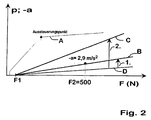
- the brake pressure p generated in the wheel brakes HL, HR, VL and VR in such a way that a predetermined Minimum target deceleration curve B or C (Fig. 2) depending of the pedal force F or a pedal actuation quantity proportional to it results.
- the thin deceleration curve A represents a normal deceleration curve with an intact brake booster, the gradient of which decreases at the modulation point.
- the gradient of the deceleration curve A after the modulation point corresponds to the gradient of the deceleration curve D, which would only be achieved if the brake booster failed.
- the approval requirement for a type test is stipulated that if the brake booster fails with a foot force of 500 N, a deceleration -a of 2.9 m / s 2 must be achieved, then in a case 1.
- the deceleration curve B becomes the minimum target -Delay history given.
- a minimum target deceleration curve C can also be specified in a case 2, which leads to a greater delay compared to the admission requirements. Due to the deceleration curve C, however, the characteristic of the braking behavior should still deviate from that of a braking behavior with an intact brake booster in order to make the driver aware of an anomaly.
- the brake pressure p is generated in the wheel brakes in such a way that it depends from the pedal force F the minimum target deceleration curve B or C results.
Landscapes
- Engineering & Computer Science (AREA)
- Transportation (AREA)
- Mechanical Engineering (AREA)
- Physics & Mathematics (AREA)
- Fluid Mechanics (AREA)
- Valves And Accessory Devices For Braking Systems (AREA)
- Regulating Braking Force (AREA)
- Braking Systems And Boosters (AREA)
Claims (2)
- Système de freinage pour véhicules automobiles avec une pédale de frein (1), avec un servofrein (2), avec un maítre-cylindre de frein (5) et avec une unité de freinage à régulation électronique (3), laquelle est disposée entre le maítre-cylindre de frein (5) et les freins des roues (AR gauche, AR droite, AV gauche, AR droite), et par laquelle, au moyen d'un appareil de commande électronique (6), la pression de freinage dans les freins des roues est réglable indépendamment de la pression d'admission régnant à la sortie du maítre-cylindre de frein (5),
caractérisé en ce que
en cas de défaillance du servofrein (2), la pression de freinage (p) dans les freins des roues (AR gauche, AR droite, AV gauche, AR droite) est générée au moyen de l'appareil de commande électronique (6) et au moyen de l'unité de freinage à régulation électronique (3), de façon à obtenir une courbe (B, C) prédéterminée de la décélération minimale de consigne en fonction d'une grandeur d'actionnement de la pédale (F) qui est directement proportionnelle à la force sur la pédale exercée par le conducteur sur la pédale de frein (1), la défaillance du servofrein (2). étant détectée lorsque, entre la pression dans la chambre à vide (21) et la pression atmosphérique, aucune différence n'est mesurée, mais la pression à la sortie du maítre-cylindre de frein (5) s'élève ou dépasse un seuil prédéterminé. - Système de freinage pour véhicules automobiles avec une pédale de frein (1), avec un servofrein (2), avec un maítre-cylindre de frein (5) et avec une unité de freinage à régulation électronique (3), laquelle est disposée entre le maítre-cylindre de frein (5) et les freins des roues (AR gauche, AR droite, AV gauche, AR droite), et par laquelle, au moyen d'un appareil de commande électronique (6), la pression de freinage dans les freins des roues est réglable indépendamment de la pression d'admission régnant à la sortie du maítre-cylindre de frein (5),
caractérisé en ce que
en cas de défaillance du servofrein (2), la pression de freinage (p) dans les freins des roues (AR gauche, AR droite, AV gauche, AR droite) est générée au moyen de l'appareil de commande électronique (6) et au moyen de l'unité de freinage à régulation électronique (3), de façon à obtenir une courbe (B, C) prédéterminée de la décélération minimale de consigne en fonction d'une grandeur d'actionnement de la pédale (F) qui est directement proportionnelle à la force sur la pédale exercée par le conducteur sur la pédale de frein (1), la défaillance du servofrein (2) étant détectée lorsque la pression dans la chambre de travail (22) est au maximum égale à la pression dans la chambre à vide (21), mais la pression à la sortie du maítre-cylindre de frein (5) s'élève ou dépasse un seuil prédéterminé.
Applications Claiming Priority (2)
| Application Number | Priority Date | Filing Date | Title |
|---|---|---|---|
| DE19743959A DE19743959A1 (de) | 1997-10-04 | 1997-10-04 | Bremsanlage für Kraftfahrzeuge |
| DE19743959 | 1997-10-04 |
Publications (2)
| Publication Number | Publication Date |
|---|---|
| EP0906858A1 EP0906858A1 (fr) | 1999-04-07 |
| EP0906858B1 true EP0906858B1 (fr) | 2003-11-26 |
Family
ID=7844643
Family Applications (1)
| Application Number | Title | Priority Date | Filing Date |
|---|---|---|---|
| EP98116488A Expired - Lifetime EP0906858B1 (fr) | 1997-10-04 | 1998-09-01 | Système de freinage pour véhicules |
Country Status (5)
| Country | Link |
|---|---|
| US (1) | US6062656A (fr) |
| EP (1) | EP0906858B1 (fr) |
| JP (1) | JP4185597B2 (fr) |
| DE (2) | DE19743959A1 (fr) |
| ES (1) | ES2212182T3 (fr) |
Families Citing this family (28)
| Publication number | Priority date | Publication date | Assignee | Title |
|---|---|---|---|---|
| DE19743960A1 (de) * | 1997-10-04 | 1999-04-08 | Bayerische Motoren Werke Ag | Bremsanlage für Kraftfahrzeuge |
| JP3458773B2 (ja) * | 1998-08-24 | 2003-10-20 | トヨタ自動車株式会社 | ブースタ異常判定装置 |
| JP3937205B2 (ja) * | 1999-04-28 | 2007-06-27 | ボッシュ株式会社 | ブレーキシステム |
| DE19925794B4 (de) * | 1999-06-05 | 2013-04-04 | Robert Bosch Gmbh | Bremsdruck-Steuereinrichtung und Verfahren zur Aktivierung und Deaktivierung einer hydraulischen Bremskraftverstärkung |
| DE19935899B4 (de) * | 1999-07-30 | 2010-12-02 | Robert Bosch Gmbh | Verfahren zum sicheren Betreiben eines Bremskraftverstärkersystems, Bremskraftverstärkersystem und Diagnosevorrichtung dafür zur Ausführung des Verfahrens |
| US6871918B2 (en) | 1999-07-30 | 2005-03-29 | Robert Bosch Gmbh | Method for the reliable operation of a brake booster system, brake booster system, and circuit therefor for implementing the method |
| JP4329205B2 (ja) * | 1999-09-10 | 2009-09-09 | トヨタ自動車株式会社 | 液圧ブレーキシステムの加圧装置異常検出装置 |
| US6557403B1 (en) * | 2000-01-07 | 2003-05-06 | Ford Global Technologies, Inc. | Lean engine with brake system |
| US6880532B1 (en) * | 2000-01-07 | 2005-04-19 | Ford Global Technologies, Llc | Engine operation parameter estimation method |
| US6493617B1 (en) * | 2000-01-07 | 2002-12-10 | Ford Global Technologies, Inc. | Lean burn engine with brake system |
| DE10018178A1 (de) * | 2000-04-12 | 2001-10-25 | Bayerische Motoren Werke Ag | Elektrisch gesteuertes, insbesondere elektromechanisches Bremssystem für ein Kraftfahrzeug |
| WO2002014131A1 (fr) * | 2000-08-11 | 2002-02-21 | Continental Teves Ag & Co. Ohg | Procede de commande d'un systeme de freinage pouvant etre regule electroniquement et circuit |
| FR2813840B1 (fr) * | 2000-09-13 | 2003-04-04 | Bosch Gmbh Robert | Servofrein |
| JP4440634B2 (ja) * | 2001-06-02 | 2010-03-24 | コンティネンタル・テーベス・アクチエンゲゼルシヤフト・ウント・コンパニー・オッフェネ・ハンデルスゲゼルシヤフト | 車両ブレーキ装置のブレーキ真空倍力装置とこのブレーキ真空倍力装置を備えた車両ブレーキ装置を運転する方法 |
| DE10210603A1 (de) * | 2002-03-11 | 2003-10-02 | Continental Teves Ag & Co Ohg | Verfahren und Vorrichtung zur Steuerung einer Fahrzeugbremsanlage mit aktiver hyraulischer Bremskraftverstärkung |
| EP1439293B1 (fr) * | 2003-01-09 | 2007-09-26 | Ford Global Technologies, LLC | Contrôle d'un moteur à combustion interne avec servofrein |
| US7686404B2 (en) * | 2005-02-23 | 2010-03-30 | Continental Teves, Inc. | Electro-hydraulic braking system |
| DE102006022734A1 (de) * | 2005-08-15 | 2007-02-22 | Continental Teves Ag & Co. Ohg | Verfahren und Vorrichtung zum Betrieb einer hydraulischen Fahrzeugbremsanlage |
| US7878053B2 (en) * | 2006-12-22 | 2011-02-01 | Gm Global Technology Operations, Inc. | Engine off brake booster leak diagnostic systems and methods |
| US8899033B2 (en) | 2007-09-19 | 2014-12-02 | GM Global Technology Operations LLC | Brake booster leak detection system |
| DE102008011606A1 (de) * | 2008-02-28 | 2009-09-03 | Robert Bosch Gmbh | Vorrichtung und Verfahren zum Erkennen einer Bremsbetätigung |
| JP5061051B2 (ja) * | 2008-07-11 | 2012-10-31 | 日立オートモティブシステムズ株式会社 | ブレーキ制御装置 |
| DE102011088938A1 (de) * | 2011-01-24 | 2012-07-26 | Continental Teves Ag & Co. Ohg | Verfahren zur Überwachung des Signalwertes eines Unterdrucksensors |
| US8874306B2 (en) * | 2011-04-05 | 2014-10-28 | Robert Bosch Gmbh | Fast detection of error conditions in vehicle vacuum sensors for a hydraulic boost compensation system |
| DE102012207554A1 (de) * | 2011-05-06 | 2012-11-08 | Continental Teves Ag & Co. Ohg | Elektronisches Steuergerät für ein Bremssystem |
| DE102011084781A1 (de) * | 2011-10-19 | 2013-04-25 | Bayerische Motoren Werke Aktiengesellschaft | Verfahren zum Sicherstellen der Bremswirkung von in einem Fahrzeug angebrachten Bremsaktuatoren |
| DE102013208671A1 (de) * | 2013-05-13 | 2014-11-13 | Robert Bosch Gmbh | Steuervorrichtung für zumindest eine elektrische Parkbremse eines Bremssystems eines Fahrzeugs und Verfahren zum Betreiben eines Bremssystems eines Fahrzeugs mit einem Bremskraftverstärker und einer elektrischen Parkbremse |
| CN115352426B (zh) * | 2022-09-14 | 2023-09-05 | 东风汽车集团股份有限公司 | 一种基于线控制动的失效保护方法和系统 |
Family Cites Families (6)
| Publication number | Priority date | Publication date | Assignee | Title |
|---|---|---|---|---|
| JPS4918675B1 (fr) * | 1969-08-10 | 1974-05-11 | ||
| DE3606136A1 (de) * | 1985-05-07 | 1986-11-13 | FAG Kugelfischer Georg Schäfer KGaA, 8720 Schweinfurt | Hilfskraftverstaerkte brems- oder kupplungsanlage |
| DE19525985A1 (de) * | 1995-07-17 | 1997-01-23 | Bayerische Motoren Werke Ag | Bremsanlage für Kraftfahrzeuge mit einem Bremskraftverstärker |
| DE19542654A1 (de) * | 1995-11-15 | 1997-05-22 | Lucas Ind Plc | Elektronische steuerbare Bremsanlage für Kraftfahrzeuge |
| DE69602002T2 (de) * | 1996-04-03 | 1999-09-30 | Lucas Industries P.L.C., Solihull | Elektronisch gesteuerter Bremskraftverstärker |
| EP1067032B1 (fr) * | 1996-12-27 | 2006-12-13 | Denso Corporation | Système de freinage pour véhicule |
-
1997
- 1997-10-04 DE DE19743959A patent/DE19743959A1/de not_active Withdrawn
-
1998
- 1998-09-01 DE DE59810249T patent/DE59810249D1/de not_active Expired - Lifetime
- 1998-09-01 EP EP98116488A patent/EP0906858B1/fr not_active Expired - Lifetime
- 1998-09-01 ES ES98116488T patent/ES2212182T3/es not_active Expired - Lifetime
- 1998-10-01 JP JP28002198A patent/JP4185597B2/ja not_active Expired - Fee Related
- 1998-10-05 US US09/166,151 patent/US6062656A/en not_active Expired - Lifetime
Also Published As
| Publication number | Publication date |
|---|---|
| US6062656A (en) | 2000-05-16 |
| JPH11157428A (ja) | 1999-06-15 |
| DE19743959A1 (de) | 1999-04-08 |
| DE59810249D1 (de) | 2004-01-08 |
| EP0906858A1 (fr) | 1999-04-07 |
| ES2212182T3 (es) | 2004-07-16 |
| JP4185597B2 (ja) | 2008-11-26 |
Similar Documents
| Publication | Publication Date | Title |
|---|---|---|
| EP0906858B1 (fr) | Système de freinage pour véhicules | |
| EP0616932B1 (fr) | Système d'assistance au freinage pour régler la pression de freinage au moyen d'un servomoteur | |
| EP1000830B1 (fr) | Ajusteur de commande de frein à redondance d'addition intégrée | |
| DE69024065T2 (de) | Mit Fluidum-Druck betätigte Verstärker für Fahrzeugbrems-Systeme | |
| DE19501760B4 (de) | Verfahren und Vorrichtung zur Steuerung eines ABS/ASR-Systems | |
| EP0906859B1 (fr) | Système de freinage pour véhicules | |
| DE19620540C1 (de) | Elektronisch steuerbare Bremsanlage | |
| EP0187901A2 (fr) | Installation de freinage commandée électriquement pour véhicules | |
| DE19750977B4 (de) | Bremsanlage | |
| WO1994022699A1 (fr) | Systeme de freinage hydraulique muni d'un systeme anti-patinage | |
| EP0857131B1 (fr) | Système de freinage avec maitre-cylindre et pompe hydraulique | |
| DE102008012387A1 (de) | Steuerung einer elektrisch betätigbaren Feststellbremse bei Ausfall eines Geschwindigkeitssignals | |
| WO2018192738A1 (fr) | Procédé servant à surveiller une mise en œuvre d'une spécification de freinage demandée de manière automatisée et système de freinage | |
| DE19925794B4 (de) | Bremsdruck-Steuereinrichtung und Verfahren zur Aktivierung und Deaktivierung einer hydraulischen Bremskraftverstärkung | |
| DE10039670A1 (de) | Pedalsimulationsvorrichtung | |
| EP1051316B1 (fr) | Dispositif de transmission de force de freinage, notamment pour vehicules a moteur | |
| DE102011085986A1 (de) | Bremsanlage | |
| DE102015006396A1 (de) | Elektrohydraulische Bremskrafterzeugungsvorrichtung für eine elektrohydraulische Kraftfahrzeug-Bremsanlage | |
| EP3784540A1 (fr) | Soupape de commande, système de freinage à commande électronique et procédé de commande du système de freinage à commande électronique | |
| DE3114431C2 (de) | Steuervorrichtung für eine in ihrer Bremsleistung veränderbare Dauerbremse | |
| DE19907338A1 (de) | Bremssystem und Verfahren zu seiner Steuerung | |
| DE102006029979A1 (de) | Verfahren zum Betrieb einer Bremsanlage eines Kraftfahrzeuges | |
| EP0360013A1 (fr) | Installation de freinage à anti-blocage pour véhicules automobiles | |
| DE102007024785A1 (de) | Bremsanlage für Kraftfahrzeuge | |
| DE102011076423A1 (de) | Verfahren und Regelvorrichtung zur Regelung eines elektrohydraulischen Bremssystems für Kraftfahrzeuge |
Legal Events
| Date | Code | Title | Description |
|---|---|---|---|
| PUAI | Public reference made under article 153(3) epc to a published international application that has entered the european phase |
Free format text: ORIGINAL CODE: 0009012 |
|
| AK | Designated contracting states |
Kind code of ref document: A1 Designated state(s): DE ES FR GB IT SE |
|
| AX | Request for extension of the european patent |
Free format text: AL;LT;LV;MK;RO;SI |
|
| 17P | Request for examination filed |
Effective date: 19990901 |
|
| AKX | Designation fees paid |
Free format text: DE ES FR GB IT SE |
|
| 17Q | First examination report despatched |
Effective date: 20010702 |
|
| GRAH | Despatch of communication of intention to grant a patent |
Free format text: ORIGINAL CODE: EPIDOS IGRA |
|
| GRAS | Grant fee paid |
Free format text: ORIGINAL CODE: EPIDOSNIGR3 |
|
| GRAA | (expected) grant |
Free format text: ORIGINAL CODE: 0009210 |
|
| AK | Designated contracting states |
Kind code of ref document: B1 Designated state(s): DE ES FR GB IT SE |
|
| REG | Reference to a national code |
Ref country code: GB Ref legal event code: FG4D Free format text: NOT ENGLISH |
|
| GBT | Gb: translation of ep patent filed (gb section 77(6)(a)/1977) |
Effective date: 20031128 |
|
| REF | Corresponds to: |
Ref document number: 59810249 Country of ref document: DE Date of ref document: 20040108 Kind code of ref document: P |
|
| REG | Reference to a national code |
Ref country code: SE Ref legal event code: TRGR |
|
| ET | Fr: translation filed | ||
| REG | Reference to a national code |
Ref country code: ES Ref legal event code: FG2A Ref document number: 2212182 Country of ref document: ES Kind code of ref document: T3 |
|
| PLBE | No opposition filed within time limit |
Free format text: ORIGINAL CODE: 0009261 |
|
| STAA | Information on the status of an ep patent application or granted ep patent |
Free format text: STATUS: NO OPPOSITION FILED WITHIN TIME LIMIT |
|
| 26N | No opposition filed |
Effective date: 20040827 |
|
| REG | Reference to a national code |
Ref country code: FR Ref legal event code: PLFP Year of fee payment: 18 |
|
| PGFP | Annual fee paid to national office [announced via postgrant information from national office to epo] |
Ref country code: ES Payment date: 20150820 Year of fee payment: 18 Ref country code: GB Payment date: 20150924 Year of fee payment: 18 |
|
| PGFP | Annual fee paid to national office [announced via postgrant information from national office to epo] |
Ref country code: FR Payment date: 20150928 Year of fee payment: 18 Ref country code: SE Payment date: 20150911 Year of fee payment: 18 |
|
| PGFP | Annual fee paid to national office [announced via postgrant information from national office to epo] |
Ref country code: IT Payment date: 20150924 Year of fee payment: 18 |
|
| PGFP | Annual fee paid to national office [announced via postgrant information from national office to epo] |
Ref country code: DE Payment date: 20150919 Year of fee payment: 18 |
|
| REG | Reference to a national code |
Ref country code: DE Ref legal event code: R119 Ref document number: 59810249 Country of ref document: DE |
|
| PG25 | Lapsed in a contracting state [announced via postgrant information from national office to epo] |
Ref country code: SE Free format text: LAPSE BECAUSE OF NON-PAYMENT OF DUE FEES Effective date: 20160902 |
|
| REG | Reference to a national code |
Ref country code: SE Ref legal event code: EUG |
|
| GBPC | Gb: european patent ceased through non-payment of renewal fee |
Effective date: 20160901 |
|
| REG | Reference to a national code |
Ref country code: FR Ref legal event code: ST Effective date: 20170531 |
|
| PG25 | Lapsed in a contracting state [announced via postgrant information from national office to epo] |
Ref country code: FR Free format text: LAPSE BECAUSE OF NON-PAYMENT OF DUE FEES Effective date: 20160930 Ref country code: DE Free format text: LAPSE BECAUSE OF NON-PAYMENT OF DUE FEES Effective date: 20170401 Ref country code: GB Free format text: LAPSE BECAUSE OF NON-PAYMENT OF DUE FEES Effective date: 20160901 |
|
| PG25 | Lapsed in a contracting state [announced via postgrant information from national office to epo] |
Ref country code: IT Free format text: LAPSE BECAUSE OF NON-PAYMENT OF DUE FEES Effective date: 20160901 |
|
| PG25 | Lapsed in a contracting state [announced via postgrant information from national office to epo] |
Ref country code: ES Free format text: LAPSE BECAUSE OF NON-PAYMENT OF DUE FEES Effective date: 20160902 |
|
| REG | Reference to a national code |
Ref country code: ES Ref legal event code: FD2A Effective date: 20181116 |