EP0907385B1 - Saug- und spülhandstück und spitze mit einziehbarem spritzschirm - Google Patents
Saug- und spülhandstück und spitze mit einziehbarem spritzschirm Download PDFInfo
- Publication number
- EP0907385B1 EP0907385B1 EP97920128A EP97920128A EP0907385B1 EP 0907385 B1 EP0907385 B1 EP 0907385B1 EP 97920128 A EP97920128 A EP 97920128A EP 97920128 A EP97920128 A EP 97920128A EP 0907385 B1 EP0907385 B1 EP 0907385B1
- Authority
- EP
- European Patent Office
- Prior art keywords
- irrigation
- tip
- suction
- tube
- handpiece
- Prior art date
- Legal status (The legal status is an assumption and is not a legal conclusion. Google has not performed a legal analysis and makes no representation as to the accuracy of the status listed.)
- Expired - Lifetime
Links
- 238000003973 irrigation Methods 0.000 title claims description 106
- 230000002262 irrigation Effects 0.000 title claims description 106
- 230000037361 pathway Effects 0.000 claims description 11
- 239000007788 liquid Substances 0.000 claims description 4
- 229920002457 flexible plastic Polymers 0.000 claims 1
- 239000012530 fluid Substances 0.000 description 15
- 239000007921 spray Substances 0.000 description 6
- 230000000399 orthopedic effect Effects 0.000 description 5
- 208000004210 Pressure Ulcer Diseases 0.000 description 3
- 238000001356 surgical procedure Methods 0.000 description 3
- 238000004519 manufacturing process Methods 0.000 description 2
- 229920003023 plastic Polymers 0.000 description 2
- FAPWRFPIFSIZLT-UHFFFAOYSA-M Sodium chloride Chemical compound [Na+].[Cl-] FAPWRFPIFSIZLT-UHFFFAOYSA-M 0.000 description 1
- 210000000746 body region Anatomy 0.000 description 1
- 210000000988 bone and bone Anatomy 0.000 description 1
- 230000008878 coupling Effects 0.000 description 1
- 238000010168 coupling process Methods 0.000 description 1
- 238000005859 coupling reaction Methods 0.000 description 1
- 230000001419 dependent effect Effects 0.000 description 1
- 230000000881 depressing effect Effects 0.000 description 1
- 230000007613 environmental effect Effects 0.000 description 1
- 239000012634 fragment Substances 0.000 description 1
- 238000000034 method Methods 0.000 description 1
- 238000012986 modification Methods 0.000 description 1
- 230000004048 modification Effects 0.000 description 1
- 230000000541 pulsatile effect Effects 0.000 description 1
- 238000007789 sealing Methods 0.000 description 1
- 239000011780 sodium chloride Substances 0.000 description 1
- 230000000007 visual effect Effects 0.000 description 1
Images


Classifications
-
- A—HUMAN NECESSITIES
- A61—MEDICAL OR VETERINARY SCIENCE; HYGIENE
- A61M—DEVICES FOR INTRODUCING MEDIA INTO, OR ONTO, THE BODY; DEVICES FOR TRANSDUCING BODY MEDIA OR FOR TAKING MEDIA FROM THE BODY; DEVICES FOR PRODUCING OR ENDING SLEEP OR STUPOR
- A61M1/00—Suction or pumping devices for medical purposes; Devices for carrying-off, for treatment of, or for carrying-over, body-liquids; Drainage systems
- A61M1/84—Drainage tubes; Aspiration tips
- A61M1/85—Drainage tubes; Aspiration tips with gas or fluid supply means, e.g. for supplying rinsing fluids or anticoagulants
-
- A—HUMAN NECESSITIES
- A61—MEDICAL OR VETERINARY SCIENCE; HYGIENE
- A61B—DIAGNOSIS; SURGERY; IDENTIFICATION
- A61B90/00—Instruments, implements or accessories specially adapted for surgery or diagnosis and not covered by any of the groups A61B1/00 - A61B50/00, e.g. for luxation treatment or for protecting wound edges
- A61B90/05—Splash shields for protection of the surgeon, e.g. splash guards connected to the apparatus
-
- A—HUMAN NECESSITIES
- A61—MEDICAL OR VETERINARY SCIENCE; HYGIENE
- A61M—DEVICES FOR INTRODUCING MEDIA INTO, OR ONTO, THE BODY; DEVICES FOR TRANSDUCING BODY MEDIA OR FOR TAKING MEDIA FROM THE BODY; DEVICES FOR PRODUCING OR ENDING SLEEP OR STUPOR
- A61M1/00—Suction or pumping devices for medical purposes; Devices for carrying-off, for treatment of, or for carrying-over, body-liquids; Drainage systems
- A61M1/71—Suction drainage systems
- A61M1/77—Suction-irrigation systems
- A61M1/774—Handpieces specially adapted for providing suction as well as irrigation, either simultaneously or independently
Definitions
- This invention relates generally to medical irrigation systems and, more particularly, to hand-held medical irrigation devices that use suction/irrigation tips.
- Suction/irrigation tips with splash shields commonly are attached to the front (distal) end of hand-held suction irrigation handpieces when localized irrigation is needed.
- the splash shield typically is a conical member having a distal rim that is intended to be pressed against and about the body region where the localized irrigation is desired.
- Such devices are commonly used, for example, in wound management environments to irrigate bed sores or other externally exposed traumatized regions of a patient's body. These devices also are commonly used in orthopedic surgical environments to clean out joints during orthopedic surgery. During orthopedic uses, however, the shield generally is removed from the distal end of the tip so that the tip may be inserted directly into the joint being treated.
- U.S. Patent No. 4,692.140 shows a typical tip that may be used with an irrigation handpiece.
- the Olson tip has an outer (suction) tube, an inner (irrigation) tube coaxially aligned within the suction tube. and a web (referred to as “pegs" in Olson) that support the distal end of the irrigation tube within the suction tube.
- the annular space between the tubes provides a suction pathway for biological debris aspirated from the irrigation site. Aspirated biological debris is directed by the tip suction pathway into a handpiece suction lumen. from which it flows through a connecting tube to a debris collection chamber.
- the tip suction pathway appears to clog easily, however, because it has a relatively small cross-sectional dimension.
- the web also obstructs debris from being drawn into the suction pathway since it partially covers the open distal end of the pathway. If the suction pathway becomes clogged, the irrigation or surgical procedure must be suspended and the suction pathway must either be cleaned out, or a new tip must be attached to the end of the suction irrigator. These additional steps are inefficient and inconvenient to both the attendant and patient.
- the Olson tip also has a flexible, conical splash shield permanently fastened to the distal end of the tip.
- the shield In addition to confining irrigation fluid to a local site, the shield undesirably prevents the irrigation outlet orifice and the suction orifice from physically contacting the surface being irrigated. This is so because the shield extends distally a certain distance from the distal end of the suction tube. In many instances, however, the physician or attendant may need to adjust this distance, for example, to bring the irrigation outlet orifice directly against the wound to increase the impact of the emitted irrigation fluid. In other instances, such as in an orthopedic surgical environmental, it often is desirable to extend the suction/irrigation tip deeply into a wound or a joint to more effectively clean that region.
- the permanently fastened Olson shield does not readily permit variation in the distance between the distal end of the tip and the site and thus, inhibits such close contact irrigation.
- One approach suggested by Olson to remedy this problem is to provide visual rings about the flexible splash shield to facilitate cutting the splash shield to a smaller size.
- the structure of the tip is permanently. A new tip must be attached to the handpiece if use of a splash shield subsequent becomes necessary.
- US 5,460,604 describes a surgical irrigation apparatus a tip member of which comprises a funnel-shaped spray shield extending divergently forward from the distal end of a suction tube.
- the neck of the spray shield can be slid off the suction tube, but only distally off the suction tube so that the suction tube can be used with or without the spray shield. In use with the spray shield, the position of the latter is fixed.
- US 4,493,694 discloses a surgical pre-aspirator comprising a suction passage and a sleeve spaced about the suction passage.
- the end of the suction passage projects slightly from the sleeve.
- a seal seals an end of the sleeve to the suction passage, and irrigation fluid is supplied between the sleeve and the suction passage.
- the invention addresses the technical problem to provide a splash protected suction/irrigation tip that facilitates close contact with an irrigation site.
- the suction .tube in a detachable suction and irrigation tip can be concentrically aligned within an outer irrigation tube.
- Irrigation liquid can be directed to the irrigation site through the annular space between the inner and outer tubes, but suction may occur through the inner lumen.
- the tip is then less subject to clogging than tips in which the suction occurs through the annular space because the largest linear dimension of the suction lumen is larger than the linear dimension of the annular irrigation lumen.
- the tip can also have a connector that is connectable to a fitting in the handpiece that fluidly communicates the tip irrigation lumen with the handpiece irrigation lumen, and the tip suction lumen with the handpiece suction lumen.
- the tip also includes a flexible splash shield that is slidably mounted on the outer tube to confine irrigation liquid to a local irrigation site. When necessary, the splash shield may be retracted so that the distal end of the tip may be positioned directly against an irrigation site.
- the splash shield can include a proximal collar and a conical body that diverges in a distal direction to a distal rim. The distal rim is typically sized to fit around and about the irrigation site.
- FIG 1 illustrates the main components of the suction irrigation system, which includes a conventional suction irrigation handpiece 10 and a suction irrigation tip 12 that is detachably connectable to the handpiece 10.
- the handpiece 10 is connected to a suction source 14 (e.g., wall.suction) through flexible suction tubing 16, and to an irrigation source 18 (e.g, a saline bag) through flexible irrigation tubing 20.
- a suction source 14 e.g., wall.suction
- irrigation source 18 e.g, a saline bag
- Irrigation fluid is pumped through the handpiece 10 and tip 12, to the irrigation site.
- Spent irrigation fluid and biological debris are aspirated through the tip 12 and handpiece 10, to a debris container (not shown).
- the handpiece 10 may be a Simpulse SoloTM suction irrigator (available from C.R. Bard, Inc. of Murray Hill, N.J.) which has a self contained pump, battery, and motor (omitted for clarity), described in more detail in co-pending U.S. patent No. 5,746,721 (assigned to C.R. Bard, Inc.).
- a suction lumen 22 and an irrigation lumen 24, both shown in phantom, extend through the entire length of the handpiece 10.
- the suction lumen 22 is connectable to a suction source 14 at a first end and terminates at a suction port 26 at a second end.
- the irrigation lumen 24 is connectable to an irrigation source 18 at the first end and terminates at an irrigation port 28 at the second end.
- Both ports 26 and 28 are formed in a fitting 30 at the distal end of the handpiece 10.
- irrigation fluid passes through the irrigation port 28 and into the tip 12.
- the irrigation fluid is emitted in a pulsatile liquid stream from the distal end 32 of the tip 12 at a pulsating frequency that is controllable by a handpiece trigger 34.
- Suction also is applied to the site through the handpiece 10 and tip 12.
- the tip 12, illustrated in cross section in FIG. 3, may be made from a hard, substantially transparent plastic.
- the tip 12 includes an inner (suction) tube 36 coaxially disposed entirely within an outer (irrigation) tube 38, a flexible splash shield 46 and a connector 48.
- the suction tube 36 defines a substantially straight flow path from the proximal end 40 of the tip 12 to the distal end 32 of the tip 12, and the annular space 44 between the suction and irrigation tubes 36 and 38 provides a pathway for irrigation fluid.
- the splash shield 46 slidably mounted to the irrigation tube 38, enables treatment to be confined to a localized treatment site.
- the connector 48 at the proximal end 40 of the tip 12 detachably connects the tip 12 to the handpiece 10.
- an irrigation connector 50 extending proximally from the tip connector 48, fluidly connects the tip annular (irrigation) space 44 to the handpiece irrigation port 28.
- a sealing O-ring 52 may encircle the irrigation connector 50 to fluidly seal that connection. Irrigation fluid therefore first passes through the flexible irrigation tubing 20 to the handpiece irrigation lumen 24. The fluid then passes through the irrigation connector 50, to the annular space 44 and is emitted at the distal end 32 of the tip 12.
- a suction connector 54 extending proximally from the tip connector 48, fluidly connects the tip suction tube 36 with the handpiece suction port 26.
- the suction connector 54 and suction tube 36 together form a substantially straight flow path for aspirated debris from the distal end 32 of the tip 12 to the handpiece suction port 26. Aspirated debris from the site therefore first passes straight through the suction tube 36, then through the suction port 26 to the handpiece suction lumen 22, and then through the flexible suction tubing 16 to the debris container.
- a clip 56 extending proximally from the connector 48 removably secures the tip 12 to the handpiece 10 by coupling with a lip 58 formed along the underside of the handpiece fitting 30. Accordingly, the tip 12 is removably connected, by a friction fit, to the handpiece 10 by the combination of the clip 56, the suction connector 54. and the irrigation connector 50.
- the tip 12 may be easily attached to and removed from the handpiece 10 with a minimum amount of force.
- the flexible shield 46 includes a proximal collar 60 and a conical body that diverges in a distal direction to a distal rim 62.
- the collar 60 is slidably mounted to the irrigation tube 38 and has an annular gripping ridge 64 to facilitate gripping the collar 60.
- a plurality of circumferential ridges 66 are included on the inner surface of the shield 46 to serve as cutting guides for cutting the shield 46.
- Vent holes 68 formed in the side of the shield 46 prevent the shield 46 from collapsing under suction and also enable air to mix with the debris aspirated from the site to avoid stagnation of debris within the shield.
- the shield 46 may be made from a flexible, substantially clear plastic that may be shaped during use to conform to the shape and contour of the irrigation site.
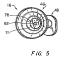
- the collar 60 may be secured to the distal end 32 of the tip 12 by both an annular flange 70 extending radially from a shower head nozzle 71 (shown in figures 2 and 3), and a discontinuous circumferential ridge 72 circumscribing the outer surface of the irrigation tube 38.
- the securing ridge 72 has two discontinuities 74 that enable the shield 46 to be more easily forced over the securing ridge 72.
- the shield 46 may be retracted proximally (FIG. 2), over the securing ridge 72, by applying a proximal force to either the rim 62 or the gripping ridge 64 on the collar 60.
- the irrigation tube 38 may be tapered slightly toward the distal end 32 of the tip 12 to increase the resistance to proximally retracting the shield 46.
- a stop ridge 76 may circumscribe the proximal end of the irrigation tube 38 to prevent the splash shield 46 from being retracted into contact with the connector 48.
- the shower head nozzle 71 fastened to the distal end 32 of the tip 12 and including an end wall 79 and a cylindrical wall extending from the end wall 80, serves a number of important functions. Primarily, as discussed above, it partially secures the splash shield 46 to the tip 12. In addition, it can be configured to emit irrigation fluid from the tip 12 in a specialized spray pattern. To that end, as shown in FIG 4, the shower head nozzle 71 has a plurality of irrigation holes 78 (e.g., nine) longitudinally formed through the cylindrical wall 80 and end wall 79, and a central suction hole 82. The diameter of the central suction hole 82 should have approximately the same diameter as the inner diameter of the suction tube 36 such as. for example, 0.1875 inches (4-8 mm).
- the number, shape, and size of the irrigation holes 78 are selected to provide a specialized spray pattern for the irrigation fluid and to regulate the force with which the irrigation fluid is emitted from the tip 12. Accordingly, the suction/irrigation tip 12 may be customized to be usable with certain pumps only. For example, when irrigating a wound on a patient's skin (e.g., a bed sore), it is preferred that the irrigation fluid be emitted from the tip 12 at a force not exceeding 15 p.s.i. (1 bar). When the tip 12 is used with the Simpulse SoloTM suction irrigator, nine holes 78 having a diameter of 0.040 inches (1 mm) have produced satisfactory results. Similarly, when used with the Simpulse PlusTM suction irrigator, available from C.R. Bard, Inc., four holes 78 having a diameter of 0.040 inches (1 mm) have produced satisfactory results.
- the tip 12 have a simple identification means that quickly and easily indicates the tip 12 that corresponds to the pump being used.
- the tip connector 48 may be color coded to correlate with the handpiece 10.
- the tip connector 48 to be used with the Simpulse SoloTM may be colored purple
- the tip connector 48 to be used with the Simpulse Plus TM may be colored green.
- the tip connector 48 may be shaped to fit into the fitting 30 of the correct pump only. In so doing, the wrong tip 12 cannot fit into the wrong pump.
- either the irrigation connector 50 or the suction connector 54 may be provided with a ridge 84 or other irregularity, and the corresponding irrigation port 28 or suction port 26 may be molded to that complimentary shape.
- the connector 48 may only be connected to the corresponding port for a fluid tight fit.
- the proximally depending cylindrical wall 80 may have an outer diameter (e.g., 0.375 inches (9.62 mm)) that is sized to be fastened to the inner surface of the irrigation tube 38.
- the outer surface of the cylindrical wall 80 is bonded to the inner surface of the irrigation tube 38.
- the inner diameter of the cylindrical wall 80 may be sized to be fastened to the outer surface of the suction tube 36.
- the inner surface of the cylindrical wall 80 is bonded to the outer surface of the suction tube 36.
- the tip 12 When used to irrigate an externally traumatized region of the body (e.g., bed sores), the tip 12 is connected to the handpiece 10, the flexible suction tubing 16 is connected to the handpiece suction lumen 22, and the flexible irrigation tubing 20 is connected to the handpiece irrigation lumen 24.
- the shield 46 may be positioned at the distal end 32 of the tip 12 and the rim 62 may be positioned at the local irrigation site.
- the attendant may then simultaneously irrigate and aspirate the site by depressing the handpiece trigger 34.
- the attendant may retract the shield 46 to put the shower head nozzle 71 directly against, or in very close proximity to, the irrigated site. After retracting the shield 46, it may be returned to the distal end 32 of the tip 12 for further localize irrigation.
- the relatively large cross-sectional area of the suction tube 36 reduces the possibility of clogging. After use, the tip 12 and handpiece 10 are discarded.
- the tip 12, flexible suction tubing 16, and flexible irrigation tubing 20 are all connected to the handpiece 10 as previously described.
- the shield 46 may be retracted entirely to the stop ridge 76 so that the suction and irrigation tubes 36 and 38 may be directly inserted into the joint being treated. Again, the relatively large diameter of the suction tube 36 reduces the possibility of clogging with bone fragments and other biological debris. After use, the tip 12 and handpiece 10 are discarded.
Landscapes
- Health & Medical Sciences (AREA)
- Heart & Thoracic Surgery (AREA)
- Biomedical Technology (AREA)
- Animal Behavior & Ethology (AREA)
- Pulmonology (AREA)
- Vascular Medicine (AREA)
- Engineering & Computer Science (AREA)
- Anesthesiology (AREA)
- Oral & Maxillofacial Surgery (AREA)
- Hematology (AREA)
- Life Sciences & Earth Sciences (AREA)
- Surgery (AREA)
- General Health & Medical Sciences (AREA)
- Public Health (AREA)
- Veterinary Medicine (AREA)
- Surgical Instruments (AREA)
- External Artificial Organs (AREA)
- Dental Tools And Instruments Or Auxiliary Dental Instruments (AREA)
- Infusion, Injection, And Reservoir Apparatuses (AREA)
Claims (13)
- Vorrichtung zum Spülen einer Spülstelle, umfassend:dadurch gekennzeichnet, dassein Handteil (10),eine Spitze (12) mit einem proximalen Ende und einem distalen Ende, wobei die Spitze einen Spülkanal (38) mit einem proximalen und einem distalen Ende aufweist;ein Verbindungselement (48) zum lösbaren Verbinden der Spitze (12) mit dem Handteil (10), undeiner elastischen Spritzblende (46), die an der Spülstelle zu positionieren ist,
die Spritzblende (46) verschiebbar auf dem Spülkanal (38) befestigt ist, wobei die Blende an dem distalen Ende der Spitze derart positioniert werden kann, dass das distale Ende (32) des Spülkanals (38) distal von der Spülstelle beabstandet ist, und in einer in proximaler Richtung zurückgezogenen Position auf der Spitze (12) angeordnet werden kann, in der das distale Ende (32) des Spülkanals (38) in die Nähe der Spülstelle gebracht oder in dieselbe eingeführt werden kann. - Vorrichtung nach Anspruch 1, wobei das Handteil ein Saugvolumen (22) und ein Spülvolumen (24) bestimmt.
- Vorrichtung nach Anspruch 1 oder 2, wobei die Spitze ferner einen Saugkanal (36) umfasst.
- Vorrichtung nach Anspruch 3, wobei der Saugkanal (36) im Wesentlichen koaxial innerhalb des Spülkanals (38) angeordnet ist.
- Vorrichtung nach Anspruch 3 oder 4, wobei der Saugkanal (36) im Wesentlichen koaxial vollständig innerhalb des Spülkanals (38) angeordnet ist.
- Vorrichtung nach einem der Ansprüche 3 bis 5, wobei der Saugkanal und der Spülkanal (36, 38) eine Bahn (44) für die Spülflüssigkeit bestimmt, wobei die Bahn (44) in Löchern (78) in dem distalen Ende (32) der Spitze (12) endet und der Saugkanal (36) vollständig innerhalb der Bahn (44) angeordnet ist.
- Vorrichtung nach einem der Ansprüche 3 bis 6, wobei der Saugkanal (36) eine im Wesentlichen geradlinige Saugflussbahn von dem distalen Ende der Spitze (12) zum proximalen Ende der Spitze bestimmt.
- Vorrichtung nach einem der Ansprüche 3 bis 7, wobei das Verbindungselement (48) ein Saug-Verbindungselement (54) zum Verbinden des Saugkanals (36) auf fluide Weise mit dem Saugvolumen (22) des Handteils besitzt, und wobei das Saug-Verbindungselement (54) und der Saugkanal (36) zusammen eine im Wesentlichen geradlinige Flussbahn von dem distalen Ende der Spitze (12) zu dem Saugvolumen (22) des Handteiles bestimmt.
- Vorrichtung nach einem der Ansprüche 1 bis 8, wobei die Spitze ferner ein Entlüftungsloch (68), das in der elastischen Spritzblende gebildet ist, umfasst.
- Vorrichtung nach einem der Ansprüche 1 bis 9, wobei der Spülkanal (38) ferner eine darauf befestigte, umgebende Erhöhung (72) und einen Flansch (70), der an dem Spülkanal distal von der Erhöhung angebracht ist, besitzt.
- Vorrichtung nach einem der Ansprüche 1 bis 10, wobei die Spritzblende aus einem elastischen Kunststoff hergestellt ist.
- Vorrichtung nach einem der Ansprüche 1 bis 11, wobei die Spitze ferner einen sich in proximaler Richtung von dem Verbindungselement erstreckenden Clip umfasst.
- Vorrichtung nach einem der Ansprüche 1 bis 12, wobei die Spritzblende konisch geformt und sich in distaler Richtung von einer Manschette (60) zu einem Rand (62) erstreckt.
Priority Applications (1)
| Application Number | Priority Date | Filing Date | Title |
|---|---|---|---|
| EP04018355A EP1477194A3 (de) | 1996-06-18 | 1997-04-03 | Saug- und Spülhandstück und Spitze mit einziehbarem Spritzscherm |
Applications Claiming Priority (3)
| Application Number | Priority Date | Filing Date | Title |
|---|---|---|---|
| US667957 | 1996-06-18 | ||
| US08/667,957 US6156004A (en) | 1996-06-18 | 1996-06-18 | Suction and irrigation handpiece and tip with retractable splash shield |
| PCT/US1997/005614 WO1997048426A2 (en) | 1996-06-18 | 1997-04-03 | Suction and irrigation handpiece and tip with retractable splash shield |
Related Child Applications (1)
| Application Number | Title | Priority Date | Filing Date |
|---|---|---|---|
| EP04018355A Division EP1477194A3 (de) | 1996-06-18 | 1997-04-03 | Saug- und Spülhandstück und Spitze mit einziehbarem Spritzscherm |
Publications (2)
| Publication Number | Publication Date |
|---|---|
| EP0907385A1 EP0907385A1 (de) | 1999-04-14 |
| EP0907385B1 true EP0907385B1 (de) | 2004-08-04 |
Family
ID=24680379
Family Applications (2)
| Application Number | Title | Priority Date | Filing Date |
|---|---|---|---|
| EP04018355A Withdrawn EP1477194A3 (de) | 1996-06-18 | 1997-04-03 | Saug- und Spülhandstück und Spitze mit einziehbarem Spritzscherm |
| EP97920128A Expired - Lifetime EP0907385B1 (de) | 1996-06-18 | 1997-04-03 | Saug- und spülhandstück und spitze mit einziehbarem spritzschirm |
Family Applications Before (1)
| Application Number | Title | Priority Date | Filing Date |
|---|---|---|---|
| EP04018355A Withdrawn EP1477194A3 (de) | 1996-06-18 | 1997-04-03 | Saug- und Spülhandstück und Spitze mit einziehbarem Spritzscherm |
Country Status (8)
| Country | Link |
|---|---|
| US (1) | US6156004A (de) |
| EP (2) | EP1477194A3 (de) |
| JP (1) | JP2002514094A (de) |
| AU (1) | AU737284B2 (de) |
| CA (1) | CA2258658C (de) |
| DE (1) | DE69730135T2 (de) |
| ES (1) | ES2225966T3 (de) |
| WO (1) | WO1997048426A2 (de) |
Cited By (1)
| Publication number | Priority date | Publication date | Assignee | Title |
|---|---|---|---|---|
| USD874643S1 (en) | 2016-01-22 | 2020-02-04 | Medline Industries, Inc. | Irrigator |
Families Citing this family (49)
| Publication number | Priority date | Publication date | Assignee | Title |
|---|---|---|---|---|
| US6746419B1 (en) | 1993-04-19 | 2004-06-08 | Stryker Corporation | Irrigation handpiece with built in pulsing pump |
| US6213970B1 (en) | 1993-12-30 | 2001-04-10 | Stryker Corporation | Surgical suction irrigation |
| US6702789B1 (en) | 1997-03-11 | 2004-03-09 | Alcove Medical, Inc. | Catheter having insertion control mechanism and anti-bunching mechanism |
| US6099494A (en) * | 1997-08-20 | 2000-08-08 | Stryker Corporation | Pulsed irrigator useful for surgical and medical procedures |
| US6402724B1 (en) * | 1997-09-09 | 2002-06-11 | Wolfe Tory Medical, Inc. | Wound irrigation shield |
| US6663610B1 (en) * | 1998-04-17 | 2003-12-16 | Leonard S. Schultz, M.D. | Smoke evacuation system |
| US7479124B2 (en) * | 1999-12-22 | 2009-01-20 | Wisconsin Alumni Research Foundation | Device for treatment of venous congestion |
| US6652488B1 (en) | 2000-09-11 | 2003-11-25 | Stryker Corporation | Surgical suction irrigator |
| EP1343549A2 (de) | 2000-12-19 | 2003-09-17 | Hill-Rom Services, Inc. | Absaugeinrichtung mit niedrigem entsorgungsrisiko |
| US20030130614A1 (en) * | 2002-01-09 | 2003-07-10 | Johnson Lanny L. | Device for delivering liquid medications or nutrients and gases to local tissue |
| EP1592466A4 (de) | 2003-02-11 | 2008-11-26 | Dilip Tapadiya | Wundirrigationsgerät |
| CA2546434C (en) | 2003-11-20 | 2013-01-22 | The Henry M. Jackson Foundation For The Advancement Of Military Medicine , Inc. | Portable hand pump for evacuation of fluids |
| BE1016163A6 (fr) * | 2004-08-18 | 2006-04-04 | Mc Anton Sa | Procede d'oxygenotherapie percutanee hyperbare par projection de fluorocarbones. |
| GB0420256D0 (en) * | 2004-09-13 | 2004-10-13 | Cassells John M | Method and apparatus for sampling and analysis of fluids |
| US8337475B2 (en) | 2004-10-12 | 2012-12-25 | C. R. Bard, Inc. | Corporeal drainage system |
| USD533274S1 (en) | 2004-10-12 | 2006-12-05 | Allegiance Corporation | Handle for surgical suction-irrigation device |
| US7976518B2 (en) | 2005-01-13 | 2011-07-12 | Corpak Medsystems, Inc. | Tubing assembly and signal generator placement control device and method for use with catheter guidance systems |
| AT501460B8 (de) * | 2005-01-14 | 2007-02-15 | Franz Pichler | Patienten-reinigungsvorrichtung |
| WO2007038643A1 (en) | 2005-09-26 | 2007-04-05 | C.R. Bard, Inc. | Catheter connection systems |
| KR200409447Y1 (ko) * | 2005-12-08 | 2006-02-24 | 유병언 | 포터블형 세척기의 세정용 물통 |
| WO2008005996A2 (en) * | 2006-07-05 | 2008-01-10 | Stryker Corporation | Medical/surgical lavage system capable of selectively and sequentially discharging either a base solution or a solution which includes a therapeutic agent |
| US7666160B2 (en) | 2006-12-29 | 2010-02-23 | Kimberly-Clark Worldwide, Inc. | Delivery device |
| US8292858B2 (en) * | 2007-07-25 | 2012-10-23 | Medline Industries, Inc. | Drain bag valve and shield |
| US9358328B2 (en) * | 2009-12-15 | 2016-06-07 | Prabhat K. Ahluwalia | Suction device |
| DE202010006116U1 (de) * | 2010-04-17 | 2010-08-05 | Interatio-Meditec Medizintechnik Vertriebs-Gmbh | Spülsystem zur Reinigung von Operationswunden |
| AU2011289568A1 (en) * | 2010-08-09 | 2013-03-21 | Innovation Technologies, Inc. | Device and method for abscess irrigation |
| US8708985B2 (en) | 2011-04-21 | 2014-04-29 | Nascent Surgical, Llc | Systems and methods for evacuating materials at a surgical site |
| WO2013036772A1 (en) | 2011-09-08 | 2013-03-14 | Corpak Medsystems, Inc. | Apparatus and method used with guidance system for feeding and suctioning |
| US10828402B2 (en) * | 2011-10-14 | 2020-11-10 | Alcon Inc. | Collar connector |
| US8945093B2 (en) | 2012-03-20 | 2015-02-03 | Minimally Invasive Surgical Technologies, Inc. | Suction device |
| US9744276B2 (en) | 2012-03-20 | 2017-08-29 | Prabhat Kumar Ahluwalia | Suction device |
| US20140039582A1 (en) * | 2012-08-06 | 2014-02-06 | Jay Wilson | Apparatus and method for using ultraviolet light with pulsatile lavage |
| EP2887976A1 (de) | 2012-08-22 | 2015-07-01 | Nascent Surgical, Llc | Rauchabsaugvorrichtung und absaugsystem |
| US12115329B2 (en) | 2013-09-06 | 2024-10-15 | Medaxis Ag | System for cleansing wounds |
| EP3041526B1 (de) | 2013-09-06 | 2020-03-04 | Medaxis Ag | Handstück zur reinigung von wunden |
| USD741495S1 (en) | 2013-12-31 | 2015-10-20 | Saint-Gobain Per.Plastics Corporation | Fluid flow sinker and fluid flow sinker assembly |
| USD791339S1 (en) | 2013-12-31 | 2017-07-04 | Saint-Gobain Performance Plastics Corporation | Fluid flow sinker and a fluid flow sinker assembly |
| WO2015164729A1 (en) | 2014-04-25 | 2015-10-29 | Saint-Gobain Performance Plastics Corporation | Fluid flow sinker |
| USD749749S1 (en) | 2014-06-11 | 2016-02-16 | Saint-Gobain Per.Plastics Corporation | Fluid flow sinker and a fluid flow sinker assembly |
| KR101546898B1 (ko) * | 2014-11-17 | 2015-08-24 | 주식회사 갈렙 | 수술용 세척기구 |
| EP3132766B1 (de) * | 2015-08-21 | 2020-10-07 | Medaxis Ag | Schutzabdeckung |
| JP6799604B2 (ja) * | 2016-02-03 | 2020-12-16 | エンテラス メディカル インコーポレイテッドEntellus Medical,Inc. | 吸引潅注装置 |
| JP7066642B2 (ja) | 2016-07-18 | 2022-05-13 | メリット・メディカル・システムズ・インコーポレイテッド | 膨張式橈骨動脈圧縮装置 |
| US12070565B2 (en) | 2019-02-04 | 2024-08-27 | The Regents Of The University Of Michigan | Device and method for wound irrigation and debridement |
| CN116113373A (zh) | 2020-08-13 | 2023-05-12 | 美国医疗设备有限公司 | 具有束紧腕带的可充气桡动脉压迫装置和使用方法 |
| US12426864B2 (en) | 2021-06-18 | 2025-09-30 | Merit Medical Systems, Inc. | Hemostasis devices and methods of use |
| CN118045250B (zh) * | 2024-04-16 | 2024-06-14 | 牡丹江医学院 | 一种外科护理用冲洗器 |
| USD1079944S1 (en) * | 2024-09-19 | 2025-06-17 | Siyi Hu | Ear cleaner |
| USD1076088S1 (en) * | 2024-12-20 | 2025-05-20 | Kexing e-commerce INC | Ear wax removal tool |
Family Cites Families (21)
| Publication number | Priority date | Publication date | Assignee | Title |
|---|---|---|---|---|
| US517274A (en) * | 1894-03-27 | Ellick h | ||
| US906711A (en) * | 1907-10-30 | 1908-12-15 | Hiram Mcclung Hill | Syringe. |
| US1178898A (en) * | 1915-11-02 | 1916-04-11 | Harold W Young | Irrigator. |
| US1602215A (en) * | 1926-04-08 | 1926-10-05 | Chester H Smith | Douche nozzle |
| US3952743A (en) * | 1973-03-28 | 1976-04-27 | Unisearch Limited | Suction device |
| US4294251A (en) * | 1978-10-17 | 1981-10-13 | Greenwald A Seth | Method of suction lavage |
| US4301798A (en) * | 1980-01-14 | 1981-11-24 | Anderson Roy A | Vaginal syringe |
| US4493694A (en) * | 1980-10-17 | 1985-01-15 | Cooper Lasersonics, Inc. | Surgical pre-aspirator |
| ATE17655T1 (de) * | 1980-12-04 | 1986-02-15 | Astra Meditec Ab | Operationsabsaugegeraet. |
| US4465479A (en) * | 1981-03-13 | 1984-08-14 | C. R. Bard, Inc. | Air vent splash guard for drip chamber |
| US4553957A (en) * | 1983-05-03 | 1985-11-19 | Alcon Laboratories, Inc. | Irrigation/aspiration handpiece |
| US4652255A (en) * | 1983-10-28 | 1987-03-24 | Miguel Martinez | Irrigating and aspirating handpiece for use in ophthalmic surgery |
| US4573979A (en) * | 1984-08-23 | 1986-03-04 | Innovative Surgical Products, Inc. | Irrigation/aspiration tip |
| US4692140A (en) * | 1985-07-01 | 1987-09-08 | Snyder Laboratories, Inc. | Lavage/suction tip with dual splash shield |
| US4769003A (en) * | 1987-08-19 | 1988-09-06 | Keith Stamler | Wound irrigation splashback shield |
| US4935006A (en) * | 1987-11-12 | 1990-06-19 | Hasson Harrith M | Suction and irrigation device with right angle and oblique openings |
| US5460604A (en) * | 1993-11-29 | 1995-10-24 | Stryker Corporation | Surgical irrigation apparatus |
| US5464390A (en) * | 1993-11-29 | 1995-11-07 | Stryker Corporation | Surgical multiorifice irrigation apparatus |
| US5496290A (en) * | 1994-11-23 | 1996-03-05 | Ackrad Laboratories, Inc. | Wound irrigation splash shield |
| US5554111A (en) * | 1995-03-16 | 1996-09-10 | Mayo Foundation For Medical Education & Research | Bone cleaning and drying system |
| US5746000A (en) | 1996-08-14 | 1998-05-05 | Textron Inc. | Headlamp assembly with magnetic indicator for horizontal and vertical positioning |
-
1996
- 1996-06-18 US US08/667,957 patent/US6156004A/en not_active Expired - Lifetime
-
1997
- 1997-04-03 ES ES97920128T patent/ES2225966T3/es not_active Expired - Lifetime
- 1997-04-03 JP JP50292498A patent/JP2002514094A/ja active Pending
- 1997-04-03 EP EP04018355A patent/EP1477194A3/de not_active Withdrawn
- 1997-04-03 WO PCT/US1997/005614 patent/WO1997048426A2/en not_active Ceased
- 1997-04-03 CA CA002258658A patent/CA2258658C/en not_active Expired - Lifetime
- 1997-04-03 EP EP97920128A patent/EP0907385B1/de not_active Expired - Lifetime
- 1997-04-03 AU AU24399/97A patent/AU737284B2/en not_active Expired
- 1997-04-03 DE DE69730135T patent/DE69730135T2/de not_active Expired - Lifetime
Cited By (2)
| Publication number | Priority date | Publication date | Assignee | Title |
|---|---|---|---|---|
| USD874643S1 (en) | 2016-01-22 | 2020-02-04 | Medline Industries, Inc. | Irrigator |
| USD896364S1 (en) | 2016-01-22 | 2020-09-15 | Medline Industries, Inc. | Irrigator |
Also Published As
| Publication number | Publication date |
|---|---|
| DE69730135T2 (de) | 2005-07-14 |
| EP1477194A2 (de) | 2004-11-17 |
| WO1997048426A2 (en) | 1997-12-24 |
| CA2258658C (en) | 2005-06-07 |
| ES2225966T3 (es) | 2005-03-16 |
| CA2258658A1 (en) | 1997-12-24 |
| WO1997048426A3 (en) | 1998-03-19 |
| JP2002514094A (ja) | 2002-05-14 |
| US6156004A (en) | 2000-12-05 |
| EP0907385A1 (de) | 1999-04-14 |
| AU737284B2 (en) | 2001-08-16 |
| EP1477194A3 (de) | 2010-09-15 |
| DE69730135D1 (de) | 2004-09-09 |
| AU2439997A (en) | 1998-01-07 |
Similar Documents
| Publication | Publication Date | Title |
|---|---|---|
| EP0907385B1 (de) | Saug- und spülhandstück und spitze mit einziehbarem spritzschirm | |
| EP0906130B1 (de) | Saug- und spülhandstück und spitze | |
| US5792098A (en) | Suction and irrigation handpiece and tip with detachable tube | |
| US11071808B2 (en) | Irrigation fluid containment systems | |
| US5827218A (en) | Surgical suction pool tip | |
| US4692140A (en) | Lavage/suction tip with dual splash shield | |
| US5591389A (en) | Method for making disposable tubular device | |
| US6712757B2 (en) | Endoscope sleeve and irrigation device | |
| US5941859A (en) | Wound irrigation shield with fluid scavenging | |
| US5460604A (en) | Surgical irrigation apparatus | |
| WO1995001755A1 (en) | Disposable aspiration tip for a cautery handpiece | |
| US5957928A (en) | Handpiece for irrigation and aspiration during eye surgery and a method for manufacturing such a handpiece | |
| AU772043B2 (en) | Medical irrigation system | |
| CA2258657C (en) | Suction and irrigation handpiece and tip | |
| AU9522701A (en) | Suction and irrigation handpiece and tip |
Legal Events
| Date | Code | Title | Description |
|---|---|---|---|
| PUAI | Public reference made under article 153(3) epc to a published international application that has entered the european phase |
Free format text: ORIGINAL CODE: 0009012 |
|
| 17P | Request for examination filed |
Effective date: 19990114 |
|
| AK | Designated contracting states |
Kind code of ref document: A1 Designated state(s): DE ES FR GB IT |
|
| D17D | Deferred search report published (deleted) | ||
| RIN1 | Information on inventor provided before grant (corrected) |
Inventor name: ALBRECHT, STEPHEN Inventor name: SAKAL, ROBERT Inventor name: TREMAINE, LAURENCE, W. |
|
| 17Q | First examination report despatched |
Effective date: 20030205 |
|
| GRAP | Despatch of communication of intention to grant a patent |
Free format text: ORIGINAL CODE: EPIDOSNIGR1 |
|
| GRAS | Grant fee paid |
Free format text: ORIGINAL CODE: EPIDOSNIGR3 |
|
| GRAA | (expected) grant |
Free format text: ORIGINAL CODE: 0009210 |
|
| AK | Designated contracting states |
Kind code of ref document: B1 Designated state(s): DE ES FR GB IT |
|
| REG | Reference to a national code |
Ref country code: GB Ref legal event code: FG4D |
|
| REF | Corresponds to: |
Ref document number: 69730135 Country of ref document: DE Date of ref document: 20040909 Kind code of ref document: P |
|
| REG | Reference to a national code |
Ref country code: ES Ref legal event code: FG2A Ref document number: 2225966 Country of ref document: ES Kind code of ref document: T3 |
|
| ET | Fr: translation filed | ||
| PLBE | No opposition filed within time limit |
Free format text: ORIGINAL CODE: 0009261 |
|
| STAA | Information on the status of an ep patent application or granted ep patent |
Free format text: STATUS: NO OPPOSITION FILED WITHIN TIME LIMIT |
|
| 26N | No opposition filed |
Effective date: 20050506 |
|
| PGFP | Annual fee paid to national office [announced via postgrant information from national office to epo] |
Ref country code: IT Payment date: 20070521 Year of fee payment: 11 |
|
| PG25 | Lapsed in a contracting state [announced via postgrant information from national office to epo] |
Ref country code: IT Free format text: LAPSE BECAUSE OF NON-PAYMENT OF DUE FEES Effective date: 20080403 |
|
| REG | Reference to a national code |
Ref country code: FR Ref legal event code: PLFP Year of fee payment: 19 |
|
| PGFP | Annual fee paid to national office [announced via postgrant information from national office to epo] |
Ref country code: ES Payment date: 20150310 Year of fee payment: 19 |
|
| PGFP | Annual fee paid to national office [announced via postgrant information from national office to epo] |
Ref country code: GB Payment date: 20150401 Year of fee payment: 19 Ref country code: DE Payment date: 20150331 Year of fee payment: 19 |
|
| PGFP | Annual fee paid to national office [announced via postgrant information from national office to epo] |
Ref country code: FR Payment date: 20150408 Year of fee payment: 19 |
|
| REG | Reference to a national code |
Ref country code: DE Ref legal event code: R119 Ref document number: 69730135 Country of ref document: DE |
|
| GBPC | Gb: european patent ceased through non-payment of renewal fee |
Effective date: 20160403 |
|
| REG | Reference to a national code |
Ref country code: FR Ref legal event code: ST Effective date: 20161230 |
|
| PG25 | Lapsed in a contracting state [announced via postgrant information from national office to epo] |
Ref country code: DE Free format text: LAPSE BECAUSE OF NON-PAYMENT OF DUE FEES Effective date: 20161101 Ref country code: FR Free format text: LAPSE BECAUSE OF NON-PAYMENT OF DUE FEES Effective date: 20160502 Ref country code: GB Free format text: LAPSE BECAUSE OF NON-PAYMENT OF DUE FEES Effective date: 20160403 |
|
| REG | Reference to a national code |
Ref country code: ES Ref legal event code: FD2A Effective date: 20180507 |
|
| PG25 | Lapsed in a contracting state [announced via postgrant information from national office to epo] |
Ref country code: ES Free format text: LAPSE BECAUSE OF NON-PAYMENT OF DUE FEES Effective date: 20160404 |