EP0907405B1 - Module emulsionneur ultracolloidal a haut rendement pour fluides reputes non miscibles et procede associe - Google Patents
Module emulsionneur ultracolloidal a haut rendement pour fluides reputes non miscibles et procede associe Download PDFInfo
- Publication number
- EP0907405B1 EP0907405B1 EP97925111A EP97925111A EP0907405B1 EP 0907405 B1 EP0907405 B1 EP 0907405B1 EP 97925111 A EP97925111 A EP 97925111A EP 97925111 A EP97925111 A EP 97925111A EP 0907405 B1 EP0907405 B1 EP 0907405B1
- Authority
- EP
- European Patent Office
- Prior art keywords
- cartridge
- fluid
- central
- discs
- tubular body
- Prior art date
- Legal status (The legal status is an assumption and is not a legal conclusion. Google has not performed a legal analysis and makes no representation as to the accuracy of the status listed.)
- Expired - Lifetime
Links
- 230000001804 emulsifying effect Effects 0.000 title claims abstract description 15
- 239000012530 fluid Substances 0.000 title claims description 64
- 238000000034 method Methods 0.000 title claims description 9
- 239000000203 mixture Substances 0.000 claims abstract description 17
- 238000002156 mixing Methods 0.000 claims abstract description 5
- 239000000839 emulsion Substances 0.000 claims description 32
- 230000000694 effects Effects 0.000 claims description 14
- 230000002093 peripheral effect Effects 0.000 claims description 7
- 230000008569 process Effects 0.000 claims description 5
- 239000000523 sample Substances 0.000 claims description 5
- 238000000265 homogenisation Methods 0.000 claims description 4
- 238000011144 upstream manufacturing Methods 0.000 claims 1
- 239000007788 liquid Substances 0.000 abstract description 12
- 239000000446 fuel Substances 0.000 abstract description 10
- 239000000047 product Substances 0.000 abstract description 4
- 238000010438 heat treatment Methods 0.000 abstract description 2
- 239000003921 oil Substances 0.000 abstract description 2
- 150000001875 compounds Chemical class 0.000 abstract 1
- 239000012263 liquid product Substances 0.000 abstract 1
- 230000007246 mechanism Effects 0.000 abstract 1
- 239000003995 emulsifying agent Substances 0.000 description 26
- XLYOFNOQVPJJNP-UHFFFAOYSA-N water Substances O XLYOFNOQVPJJNP-UHFFFAOYSA-N 0.000 description 9
- 239000007787 solid Substances 0.000 description 8
- 238000006073 displacement reaction Methods 0.000 description 7
- 238000002485 combustion reaction Methods 0.000 description 5
- 238000005096 rolling process Methods 0.000 description 5
- 235000013305 food Nutrition 0.000 description 4
- 230000003534 oscillatory effect Effects 0.000 description 4
- 238000006243 chemical reaction Methods 0.000 description 3
- 230000006835 compression Effects 0.000 description 3
- 238000007906 compression Methods 0.000 description 3
- 238000004519 manufacturing process Methods 0.000 description 3
- 230000000903 blocking effect Effects 0.000 description 2
- 239000002131 composite material Substances 0.000 description 2
- 235000005911 diet Nutrition 0.000 description 2
- 230000037213 diet Effects 0.000 description 2
- 230000010355 oscillation Effects 0.000 description 2
- 238000012360 testing method Methods 0.000 description 2
- 230000007704 transition Effects 0.000 description 2
- 239000002699 waste material Substances 0.000 description 2
- 101100536354 Drosophila melanogaster tant gene Proteins 0.000 description 1
- 239000000654 additive Substances 0.000 description 1
- 239000000956 alloy Substances 0.000 description 1
- 229910045601 alloy Inorganic materials 0.000 description 1
- 230000003796 beauty Effects 0.000 description 1
- 238000004140 cleaning Methods 0.000 description 1
- 239000012141 concentrate Substances 0.000 description 1
- 238000010411 cooking Methods 0.000 description 1
- 235000014541 cooking fats Nutrition 0.000 description 1
- 239000006071 cream Substances 0.000 description 1
- 238000001514 detection method Methods 0.000 description 1
- 239000010771 distillate fuel oil Substances 0.000 description 1
- 238000005265 energy consumption Methods 0.000 description 1
- 235000021183 entrée Nutrition 0.000 description 1
- 239000006260 foam Substances 0.000 description 1
- 239000000295 fuel oil Substances 0.000 description 1
- 239000010763 heavy fuel oil Substances 0.000 description 1
- 229930195733 hydrocarbon Natural products 0.000 description 1
- 150000002430 hydrocarbons Chemical class 0.000 description 1
- 238000009434 installation Methods 0.000 description 1
- 230000003993 interaction Effects 0.000 description 1
- 239000011872 intimate mixture Substances 0.000 description 1
- 235000004213 low-fat Nutrition 0.000 description 1
- 235000013310 margarine Nutrition 0.000 description 1
- 239000003264 margarine Substances 0.000 description 1
- 238000005259 measurement Methods 0.000 description 1
- 239000002184 metal Substances 0.000 description 1
- 230000004048 modification Effects 0.000 description 1
- 238000012986 modification Methods 0.000 description 1
- 239000003208 petroleum Substances 0.000 description 1
- 230000000704 physical effect Effects 0.000 description 1
- 239000004033 plastic Substances 0.000 description 1
- 238000002360 preparation method Methods 0.000 description 1
- 230000009467 reduction Effects 0.000 description 1
- 238000011160 research Methods 0.000 description 1
- 230000004044 response Effects 0.000 description 1
- 230000002441 reversible effect Effects 0.000 description 1
- 125000006850 spacer group Chemical group 0.000 description 1
- 239000007858 starting material Substances 0.000 description 1
- 230000003068 static effect Effects 0.000 description 1
- 239000000126 substance Substances 0.000 description 1
- 239000000725 suspension Substances 0.000 description 1
- 235000013311 vegetables Nutrition 0.000 description 1
Images


Classifications
-
- B—PERFORMING OPERATIONS; TRANSPORTING
- B01—PHYSICAL OR CHEMICAL PROCESSES OR APPARATUS IN GENERAL
- B01F—MIXING, e.g. DISSOLVING, EMULSIFYING OR DISPERSING
- B01F31/00—Mixers with shaking, oscillating, or vibrating mechanisms
- B01F31/80—Mixing by means of high-frequency vibrations above one kHz, e.g. ultrasonic vibrations
- B01F31/81—Mixing by means of high-frequency vibrations above one kHz, e.g. ultrasonic vibrations by vibrations generated inside a mixing device not coming from an external drive, e.g. by the flow of material causing a knife to vibrate or by vibrating nozzles
-
- B—PERFORMING OPERATIONS; TRANSPORTING
- B01—PHYSICAL OR CHEMICAL PROCESSES OR APPARATUS IN GENERAL
- B01F—MIXING, e.g. DISSOLVING, EMULSIFYING OR DISPERSING
- B01F23/00—Mixing according to the phases to be mixed, e.g. dispersing or emulsifying
- B01F23/40—Mixing liquids with liquids; Emulsifying
- B01F23/41—Emulsifying
- B01F23/411—Emulsifying using electrical or magnetic fields, heat or vibrations
- B01F23/4111—Emulsifying using electrical or magnetic fields, heat or vibrations using vibrations
-
- B—PERFORMING OPERATIONS; TRANSPORTING
- B01—PHYSICAL OR CHEMICAL PROCESSES OR APPARATUS IN GENERAL
- B01F—MIXING, e.g. DISSOLVING, EMULSIFYING OR DISPERSING
- B01F25/00—Flow mixers; Mixers for falling materials, e.g. solid particles
- B01F25/40—Static mixers
- B01F25/45—Mixers in which the materials to be mixed are pressed together through orifices or interstitial spaces, e.g. between beads
-
- B—PERFORMING OPERATIONS; TRANSPORTING
- B01—PHYSICAL OR CHEMICAL PROCESSES OR APPARATUS IN GENERAL
- B01F—MIXING, e.g. DISSOLVING, EMULSIFYING OR DISPERSING
- B01F2215/00—Auxiliary or complementary information in relation with mixing
- B01F2215/04—Technical information in relation with mixing
- B01F2215/0413—Numerical information
- B01F2215/0436—Operational information
- B01F2215/044—Numerical composition values of components or mixtures, e.g. percentage of components
-
- B—PERFORMING OPERATIONS; TRANSPORTING
- B01—PHYSICAL OR CHEMICAL PROCESSES OR APPARATUS IN GENERAL
- B01F—MIXING, e.g. DISSOLVING, EMULSIFYING OR DISPERSING
- B01F2215/00—Auxiliary or complementary information in relation with mixing
- B01F2215/04—Technical information in relation with mixing
- B01F2215/0413—Numerical information
- B01F2215/0436—Operational information
- B01F2215/0468—Numerical pressure values
Definitions
- the present invention relates to a module emulsifier for the production of a mixture or a ultracolloidal emulsion from at least two immiscible fluids including a primary fluid and in particular a fatty liquid fluid mixed with water and / or various liquid or gaseous additives.
- the emulsifier is formed by a stack of fitted annular parts fitted in a tube closed at each of its ends by a fitting. These annular parts are slidably mounted along of a median longitudinal axis and kept apart from each other by a central lateral extension tubular achieving a nesting effect. Each annular part has peripheral notches of two kinds and their arrangement is such that they form forced baffles in one piece annular to each other.
- the stack forms a block maintained in a position of elastic equilibrium at a distance ends of the tube by helical springs which at the same time ensure the cohesion of the whole.
- the fluid arrives through the ends hollow of the median longitudinal axis on which are mounted the annular parts.
- the fluid mixture crosses lengthwise the annular volume occupied by the annular parts and emulsified tube spring. The block is thus subjected to an oscillatory movement from the pulsating effects of cavitation.
- this emulsifier thus presents a significant pressure drop and an emulsifying effect limited to that caused by passing through baffles.
- the second invention derives from the first in its general characteristics.
- the stack is constituted by the succession of perforated plates cylindrical and through-pass spacers in biconical restrictions separated from each other by a empty space, the whole forming a block adjusted in a tubular body.
- the through passages of the plates and successive dividers are offset laterally so as to form baffles.
- This mixer consists of moving masses on a median longitudinal axis separated from each other by a spring. These masses are full and thick. They can only move in oscillating movements a low speed does not allow to consider a self-resonant of sufficient frequency to create a emulsion and a fortiori an ultrafine emulsion such as to which the present invention relates.
- the object of the invention is to produce a ultrafine emulsion from two non-liquid miscible and this with the least possible energy.
- the invention it is possible to produce ultra intimate blends and push the limit of stability and fineness up to a quality ultracolloid without physical modification substantial for several weeks or even for several months and this for a consumption quite made reduced energy.
- hydrocarbons used as fuels known as fuel oil, light or heavy fuel oil or any other.
- An ultracolloidal emulsion provides cleaner combustion, self-cleaning for the fireplace and allows an appreciable saving of energy.
- the invention relates to a high performance emulsifier module achieving the preparation of a product with physical properties according to claim 1.
- the high efficiency emulsifier module for fluids known to be immiscible with a view to making them mixtures and / or emulsions of high stability according to the invention can be used alone or in groups with one or more other modules connected in series, in parallel or otherwise.
- tubular body having at its first end a inlet block into which fluids arrive pressure and at its second end an outlet block, in that the internal volume of the tubular body is occupied by a plurality of hollow cartridges, one of which of the front faces is through for the fluid and connected to each other and to the end blocks at each times by a longitudinal elastic connection, cartridges mounted in series separated from each other by a spring ensuring the elastic connection between them and with tube end blocks, cartridges being open on their opposite front face and adjusted to the section of the tubular body in the manner a piston, the cartridges each containing a plurality of vibrating discs slidably mounted on a coaxial hollow axis having along its length a plurality of outlet orifices making part of fluid supply, discs discovered and alternately covered by movement oscillating movement of the vibrating discs, the cartridges being oscillating determined by their physical characteristics and those of the elastic longitudinal connections.
- the input block is a mixer formed by a central channel with conical inlet and divergent outlet towards the inside of the central tubular body by a tube reported diverging whose projecting end serves as seat at the longitudinal elastic end link connecting the input block to the adjacent cartridge and there has two side entrances through two conduits transverse opening offset in the channel central and communicating with secondary conduits longitudinal opening into the tubular body.
- the present invention is based on the principles of turbulence, cavitation, shear and rolling applied to fluids deemed not miscible at low and medium pressure and the means obtain an excellent mixture or emulsion quality in both finesse and stability.
- emulsifier module all modules and groups of modules targeted by the invention, namely mixer modules, homogenizers, pre-emulsifiers, emulsifiers and homogenizers.
- module or the grouping of modules according to the invention can serve as a homogenizer liquids or fluids including unstable or of them.
- modules homogenizers or emulsifiers or homogenizers / emulsifiers all referred to below as emulsifiers allowing to realize by grouping an emulsifier multi-storey complex with interposition possible pump.
- the input block 2 is, as the case may be, an input block 3-way mixer 4, for a single input block single channel 5.
- the supply circuits of the different tracks include a pump (not shown) intended for supply the module with the fluid or mixture of fluids under pressure.
- mixer block 4 two ways are provided for the fluids to be emulsified, by example but not limited to, water and a fluid vector, for example a petroleum fatty liquid, vegetable, animal or other, the third way being provided for an additional liquid fluid for example of the reactive or waste or dye or other type.
- a fluid vector for example a petroleum fatty liquid, vegetable, animal or other
- an additional liquid fluid for example of the reactive or waste or dye or other type.
- Each end block 2 or 3 is mounted on the cylindrical body 1 for example by screwing with interposition of a seal respectively 6 and 7.
- the cylindrical tubular body 1 contains the minus an oscillating cartridge such as 8 or more oscillating cartridges, for example four, such as 9, 10, 11, 12 ( Figure 1), the number of which may vary in the framework of the basic module.
- Oscillating cartridges are weakly mounted cylindrical hollow bodies 13 adjusted in this cylindrical body in the manner of a piston to allow their easy sliding.
- the oscillating cartridges 8 are interconnected and to the inlet and outlet end blocks by elastic bonds, for example in the form of end springs 14 and 15 and intermediate 16, 17, 18 so-called feedback, realizing real axial longitudinal multiple suspension in which cartridges are masses that come in oscillation by the passage of the fluid or mixture of pressurized fluids.
- each cartridge leads to one of its transverse ends by a front face rear open 19, the body of each cartridge being closed at its other transverse end by a front wall 20 through for the fluid by full example but perforated by holes such as 21 of which the surface of the rear opposite face represents the bottom of the cartridge. Drill holes 21 of passage of the fluid provided in this front wall 20 are for example regularly distributed radially and circularly.
- the front wall 20 has a cylindrical bulge 22 possibly profiled for hydrodynamic reasons protruding into central position to serve as a seat for one of the springs forming the elastic connection.
- the bulge cylindrical 22 has a threaded bore 23.
- each cartridge is occupied by a series of vibrating discs such as 24 sliding mounted with minimal play to each other following the others on a hollow interior median axis and coaxial 25 having a first blind end at transverse terminal shoulder 26 forming a stop and a second open and threaded end 27 in diameter lower delimiting a shoulder-stop 28.
- the threaded end 27 is screwed into the bore tapped 23 made in the center of the cylindrical bulge 22 projecting from the full front wall 20 of the cartridge.
- the vibrating discs 24 occupy each times the entire cross section of the cartridge and have only a slight clearance with the wall inner cylinder of the cartridge so that that they can slide freely in the cartridge without requiring significant effort to defeat the friction and without blocking.
- the discs occupy almost the entire length of the central hollow axis coaxial 25 so there is only a little play important between them allowing small displacements mutual axial transverses.
- the hollow axis 25 has holes cross calibrated such as 29, for example from semi-circular or triangular section. These orifices are present for example only on the half-part anterior of its length. During their movements axial representing the displacements of oscillation, they are alternately discovered and then covered by the central opening of each vibrating disc by which they are mounted on the hollow axis. These orifices are divided into groups 30, 31, 32 arranged on a same circular line of cross section. We can indicate that the presence of four distributed orifices angularly at 90 ° is sufficient for each line of section.
- the orifices 29 of the first group 30 are located in the immediate vicinity of the shoulder-stop 28 of the threaded end 27 of the hollow axis 25. The following are distant for example from the thickness of a disc then two discs. This provision does not constitutes of course that an example of execution not limiting.
- the discs 24 are plated against each other under the effect of the spring rear opposite to the one who leans on the wall full front 20.
- This rear spring presses on the central part of the last disc which serves as seat. The force of this spring pushes all of the discs 24 against the bottom of the cartridge which is the rear face of the front wall 20.
- bottom end disc 33 i.e. the closed end disc. This one is kept in contact with the back side of the front wall 20 by the spring pushing effect adjacent.
- end disc rear 34 i.e. open end disc which serves as a bearing surface for the adjacent spring by its central part having a cylindrical projection 35.
- intermediate discs differ in presence or not perforations in their central part. It's about solid 36 and perforated 37 intermediate discs. They have the following general conformation.
- Each intermediate disc has a central opening such as 38 of diameter close to the outer diameter of the hollow axis 25 so that slide freely on the guide, for example loose fit.
- Each central opening 38 is delimited on each side by a solid border 39 and 40.
- the discs also have on each of their face in the central part a circular projection 41 and 42 concentric with a solid border and crenellated by axial notches such as 43.
- the notches 43 of these crenellated projections 41.42 are offset angularly between them on a regular basis and by example angularly offset from a projection to the protrusion from the opposite side.
- Each crenellated projection 41 or 42 delimits with each corresponding solid border 39 or 40 of the central opening 38 a full annular range 44 or perforated 45 whose perforations 46 occur in regular and crown arrangement and serve axial passages.
- the presence or not of these perforations marks the main difference between intermediate discs 36 and 37.
- Both solid and perforated discs have on their periphery a plurality of notches peripherals such as 47 more or less numerous delimited by notches such as 48 plus or shallower and more or less wide.
- the notches full intermediate disks 36 are more many as the notches of the intermediate discs perforated 37.
- the notches delimiting the notches peripheral and axial notches 43 of projections crenellated 41,42 are at an angle to the line of general longitudinal axis.
- the two end discs 33 and 34 are full.
- the closed end disc or bottom disc 33 is analogous to a full intermediate disc.
- the open end disc or rear disc 34 has the same general conformation as that of full intermediate discs but in which the peripheral notches are more numerous and the crenellated projection is replaced on the facing side to the spring, by the cylindrical projection 35 serving to sits at said spring.
- the solid intermediate discs 36 and perforated 37 are alternated.
- the constraint of presence of two solid discs at the end imposes a number odd discs.
- the internal volume of the tubular body is occupied by a succession of springs and cartridges, the minimum being a cartridge and two springs like shown in figure 2.
- Each end volume delimited by a end block 2 or 3 and the adjacent cartridge represents a passage and turbulence chamber of the fluid or mixture of fluids.
- a first turbulence chamber 49 and the other end of the tubular body a final chamber of turbulence 50.
- the volumes located between the cartridges containing the connecting springs constitute intermediate turbulence chambers such as 51.52.53.
- the input block is single 5 or mixer type 4.
- the simple input block 5 is located under the form of a closure piece 54 screwed into the threaded end of the body 1 with the interposition of a O-ring 6.
- the closure piece 54 has a central passage 55 with conical end opening 56, passage lined with a divergent tube 57 inwards of the tubular body 1 projecting outside of the closure piece on the turbulence chamber side 49 by a double shoulder stop part, including a stop depression 58 on the obturation part, followed by an end stop 59 forming a seat for the end of the spring.
- the stops can be in one technical form 60 (part circled in Figure 1).
- the elaborate end block forming a mixer 4 is a different part 61 and presents approximately the same central channel 55 at entrance conical 56 lined with a divergent tube 62 similar to previous and the tapered end 56 of an entry into line.
- Two transverse annex entrances 63 and 64 open perpendicularly into the central channel 55 near the tapered end 56 but slightly longitudinally offset to avoid interaction and output disturbances.
- These additional entries transverse 63 and 64 are interior passages cylindrical 65,66 narrowing at the end by a conical transition 67,68.
- a secondary duct longitudinal 69.70 crosses the work axially obturation between each conical transition 67,68 and the adjacent turbulence chamber 49 in which opens the central channel 55.
- the mixing takes place partly by venturi effect in the central channel 55 and partly in the adjacent turbulence chamber 49 by the longitudinal secondary conduits 69.70.
- the central channel 55 passes the fluid main under pressure, i.e. the one with larger pressure flow from a supply circuit comprising a pump (not shown).
- a supply circuit comprising a pump (not shown).
- the canals adjacent are preferably injected under pressure by pumps (not shown) the fluids to mix or emulsifier liquid for example from water, liquid and other waste in quantity variable depending on the application typically targeted between 10 and 20% or exceptionally more or much more.
- the central channel 55 can receive the fluid already emulsified.
- the single input block emulsifier module the inlet channel of which has a divergent nozzle or a tubing with a divergent inner conduit 57 extended by an abutment projection 58.59 serving as a seat for the spring contains several vibrating cartridges, the last one is connected to the output block 3 by the last elastic longitudinal link 15.
- the output block 3 in the form of a part shutter 71 performs several functions. First the evacuation function via a head output central 72 forming a manifold with several output channels including a central channel 73 and two oblique channels 74.75 opening into a chamber collector 76 with discharge through an outlet 77 shifted at an angle.
- the head outlet 72 is axially movable along a guide longitudinal 78 under the effect of a needle screw 79.
- the outlet head 72 serves as a seat by a recessed edge 80 at the last spring 15 against reaction. By its movement, it fulfills the function more or less significant static compression of the last spring and by reaction of all the springs of the tubular body.
- the output block also fills two other functions.
- the first relates to the detection of vibrations in the form of a vibration sensor 81 providing information about the level and vibrational state inside the body tubular for proper position adjustment of the outlet head to adapt the different vibrational regimes.
- the second concerns a stop function adjustable safety in the form of a rod 82 sliding and lockable at a specific position or any other way.
- the end of this rod is intended to maintain the end disc 34 of the last cartridge remote from the end of the probe 81.
- the emulsifier module and its variants according to the invention may be used separately or by grouping, in series, in parallel or otherwise grouped or separated by a pump thus forming one or more floor (s).
- the bottom disc 33 in contact with the bottom of the cartridge is placed so that its opening central completely clears the holes 29 of the first group 30 of the hollow axis 25 when the bottom disc 33 is in contact with the bottom wall of the cartridge so as to keep these orifices of the first group open regardless of the disk movements of background 33.
- the fluid outlet from the axis holes hollow center as well as the reciprocating movement of central disc openings above the holes generate vibrations that propagate to discs and a shear-rolling phenomenon which improves greatly the fineness of the emulsion.
- This phenomenon exists from low pressure values located at a few bars level and increases with pressure up to values between 10 and 100 bars. he there is an operating regime which generates composite vibrations of which one of the components corresponds to the frequency of vibration of the discs.
- This diet depends not only on the characteristics disc mechanics, but also characteristics fluid including viscosity, pressure and debit. It seems obvious that this diet is research because it provides maximum performance.
- This vibration of the discs corresponds to a third operating frequency, the first being that of the oscillatory movement of the cartridges and the second that of the alternative movements of discs along the hollow axis 25.
- composition of these three phenomena vibratory, the fluid flow vibration the along the cartridges and tubular body and the shear-rolling allow to obtain the performance and high efficiency of the emulsifier as well as the high quality of the emulsion.
- the cartridges 8 slide freely in the tubular body like a piston in a cylinder.
- the elastic longitudinal connections to feedback spring stressed in compression generate oscillating movements of each cartridge around a rest position under the effect of incident pressure.
- Each cartridge is animated by a movement ensemble AC at another lower frequency than that of discs mainly determined by various factors including flow, pressure and viscosity of the fluid, as well as the mass of each cartridge and stiffness characteristics of springs.
- the cartridge (s) are pushed by the pressure of the incident flow generating a force greater than the return force of the connecting spring downstream causing the cartridge to move after compression of this spring.
- the spring develops a restoring force which will generate a opposite movement as soon as the pressure on the cartridge will decrease due to the larger opening of the internal path for the fluid.
- the holes 29 of the hollow axis 25 are open and then closed alternately by movement on the hollow axis of the wall delimited by the opening central 38 of the adjacent discs ( Figure 13).
- This high shear-rolling effect frequency greatly improves the smoothness and emulsion stability.
- each module There is a pre-emulsifier module formed of a mixer input block multi-channel 4, a turbulence chamber 49, one or more of several cartridges linked by the links longitudinal elastic and outlet block 3 with stop 82 and vibration probe 81.
- the invention also relates to the method homogenization and emulsion using the means previously described according to claim 11.
- the process involves mixing a fluid vector under pressure with one or more fluid (s) secondary (s) in a multi-channel input block and preferably with central channel and venturi effect, homogenize this mixture in a first turbulence located at a first end of a body tubular homogenization-emulsion closed on its first end by the input block.
- the method then consists in carrying out a oil-in-water type emulsion through the passage of fluids through one or more cartridges each containing vibrating discs, cartridges interconnected and at both ends of the body tubular by elastic connections, the assembly being as described above.
- the process ultimately consists in making unblock the fluid in a final chamber turbulence blocked by the outlet block, to adjust the position of the outlet head carrying the end of the last elastic connection spring to place in the resonance zone of the vibrating elements or oscillating elements contained in the tubular body, the adjustment being done from information or state a measurement probe or a vibration sensor providing information on the vibrational phenomena to inside the tubular body.
- the method also relates to the use of several modules grouped in series, in parallel or otherwise, possibly with the interposition of a pump between two successive modules or between two module groups.
Landscapes
- Chemical & Material Sciences (AREA)
- Chemical Kinetics & Catalysis (AREA)
- Dispersion Chemistry (AREA)
- Colloid Chemistry (AREA)
Description
- grande précision de réglage des proportions entre les deux fluides principaux,
- faible consommation énergétique,
- coût peu important devant les résultats,
- domaines d'application particulièrement nombreux dont l'agro-alimentaire, la cosmétologie, la chimie et la pétrochimie, les turbines à gaz, les brûleurs de chaudières, les moteurs à combustion interne et de nombreux autres,
- possibilité d'effectuer des émulsions ternaires, et bien d'autres domaines d'application dans lesquels une émulsion fine ou une homogénéisation poussée est recherchée.
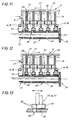
- la figure 1 est une vue en coupe longitudinale du module émulsionneur de base selon l'invention montrant les deux variantes du bloc d'entrée ;
- la figure 2 est une vue en coupe longitudinale d'une variante utilisable en tant que pré-émulsionneur ;
- la figure 3 est une vue en perspective d'une cartouche oscillante ;
- la figure 4 est une vue en perspective en éclaté de la cartouche oscillante et de son contenu ;
- les figures 5 et 6 sont deux vues en perspective montrant chacune une face d'un disque non perforé ;
- les figures 7 et 8 sont deux vues en perspective montrant chacune une face d'un disque perforé ;
- les figures 9 et 10 sont des vues en perspective des variantes de disques à entailles en biais ;
- les figures 11 et 12 sont des demi-coupes longitudinales schématiques sur la longueur d'une cartouche illustrative du fonctionnement, respectivement au repos et au travail ;
- la figure 13 est une vue schématique illustrant le mouvement de la partie centrale d'un disque devant un orifice de l'axe creux.
Claims (13)
- Module émulsionneur à haut rendement pour fluides réputés non miscibles en vue de la réalisation de mélanges et/ou d'émulsions fines de grande stabilité, formé d'un corps tubulaire (1) fermé à sa première extrémité par un bloc d'entrée (2) dans lequel arrive au moins un fluide sous pression et à sa deuxième extrémité par un bloc de sortie (3) par lequel sort le fluide émulsionné, le corps tubulaire (1) présentant à son intérieur des éléments mobiles montés à coulissement sur un axe caractérisé par :et en ce que la liaison élastique reliant la face aval ouverte de la cartouche s'appuie sur les disques vibrants de façon à les contraindre élastiquement en direction aval,au moins un axe creux central présentant sur au moins une partie de sa longueur une pluralité d'orifices latéraux de sortie (29) réalisant une partie de l'arrivée du mélange fluide dans la cartouche, l'axe creux étant fermé à son extrémité aval,au moins une cartouche creuse (8) traversée par le mélange de fluides correspondant à chaque axe creux qu'elle contient et qui est monté immobile par rapport au corps de la cartouche dont la face d'extrémité amont comporte des passages localisés du fluide et dont l'extrémité aval est entièrement ouverte, cartouche reliée élastiquement au niveau de chacune de ses extrémités au corps voisin soit d'extrémité du tube soit à une cartouche adjacente par une liaison élastique (14-18), en ce que la ou les cartouches contiennent l'axe creux immobilisé au corps de la cartouche et une pluralité de disques vibrants montés à coulissement libres sur l'axe creux central coaxial propre à la cartouche et le long de la paroi latérale de chaque cartouche, le corps cylindrique de chaque cartouche étant ajusté pour se déplacer en translation le long de la surface latérale intérieure du corps tubulaire (1) du module émulsionneurdes disques vibrants contenus dans chaque cartouche montés à libre coulissement le long de chaque axe creux à orifices latéraux mobiles alternativement entre une position dans laquelle ils découvrent par leur base un ou plusieurs orifices latéraux de l'axe creux sur lequel ils sont montés et une position dans laquelle leur base obture les orifices latéraux correspondants, ces disques étant traversants pour le fluide
et en ce que le fluide arrive dans la cartouche par deux voies, l'une par sa face frontale traversante pour le fluide et l'autre par l'axe creux qui le distribue à l'intérieur de la cartouche par ses orifices latéraux découverts et recouverts alternativement par le mouvement oscillant le long de l'axe creux des disques vibrants (24) sous l'effet du passage du fluide, les cartouches (8) étant animées d'un autre mouvement oscillant déterminé par les caractéristiques physiques des cartouches et celles des liaisons élastiques longitudinales (14-18). - Module émulsionneur selon la revendication 1 caractérisé en ce que le bloc d'entrée (2) est un mélangeur (4) formé d'un canal central (55) à entrée conique (56) recevant le fluide principal sous pression et à sortie divergente vers l'intérieur du corps central tubulaire (1) par un tube rapporté divergent (62) dont l'extrémité en saillie sert de siège à la liaison élastique longitudinale d'extrémité reliant le bloc d'entrée à la cartouche adjacente et en ce que le bloc d'entrée à mélangeur (4) comporte deux entrées latérales (63,64) par deux conduits transversaux recevant les autres fluides sous pression et débouchant de façon décalée dans le canal central (55) et communiquant avec des conduits secondaires longitudinaux (69,70) débouchant dans le corps tubulaire (1).
- Module émulsionneur selon la revendication 1 caractérisé en ce que le bloc d'entrée (2) est un bloc simple (5) à canal central (55) recevant le fluide principal sous pression et comportant un tubage rapporté (57) divergent vers l'intérieur du corps tubulaire (1), tubage présentant une extrémité en saillie à l'intérieur du corps tubulaire qui sert de siège à la liaison élastique longitudinale d'extrémité (14) reliant le bloc d'entrée (2) à la cartouche adjacente à travers une chambre de turbulence (49).
- Module émulsionneur selon la revendication 1 caractérisé en ce que le bloc de sortie (3) est une pièce d'obturation (71) vissée sur l'extrémité arrière du module et présentant en partie centrale une tête de sortie (72) mobile axialement le long d'un guide central (78) sous l'effet d'une vis-pointeau (79), tête de sortie (72) formant un collecteur à canal central (73) et à au moins deux canaux obliques de sortie (74,75) débouchant dans une chambre collectrice (76), la tête de sortie présentant une bordure extérieure (80) servant de siège au dernier ressort de liaison (15) et en ce que la pièce d'obturation (71) comporte une sonde de mesure (81) des mouvements vibratoires en vue du réglage et une butée de sécurité (82) qui maintient le dernier disque à distance de l'extrémité de la sonde.
- Module émulsionneur selon l'une quelconque des revendications précédentes, caractérisé en ce que chaque cartouche présente une paroi frontale (20) perforée et à saillie centrale (22) taraudée de part en part, une extrémité arrière ouverte et un volume intérieur libre occupé par les disques vibrants (24) portés coulissants sur l'axe creux (25) monté coaxial par son extrémité filetée (27), axe creux (25) terminé par un épaulement de butée (28) et dont toute la longueur est occupée par des disques vibrants (24).
- Module émulsionneur selon les revendications 1 et 4 caractérisé en ce que les disques vibrants (24) présentent une ouverture centrale (38) délimitée par une bordure centrale (35) par laquelle ils sont montés coulissants sur l'axe creux (25) et des encoches périphériques (47) délimitées par des entailles (48), les disques vibrants (24) comportant sur chacune de leur face entre la bordure centrale (35) et les encoches périphériques (47) une saillie cylindrique crénelée (41,42).
- Module émulsionneur selon les revendications 5 et 6 caractérisé en ce que sur certains disques (37), l'espace situé entre la bordure centrale (35) et chaque saillie crénelée (41,42) est percé par une succession de perforations (46).
- Module émulsionneur selon les revendications 5 et 6, caractérisé en ce que le disque arrière (34) situé au niveau de l'extrémité arrière est non perforé et présente sur sa partie centrale face à l'extérieur une saillie (35) servant de siège au ressort de liaison avec la cartouche adjacente ou l'extrémité du corps tubulaire (1).
- Module émulsionneur selon l'une quelconque des revendications précédentes, caractérisé en ce qu'il est composé d'une pluralité de modules disposés en étages ou groupés autrement.
- Module émulsionneur selon la revendication précédente, caractérisé en ce qu'il est composé d'une pluralité de modules disposés en étages ou groupés autrement avec interposition d'au moins une pompe.
- Procédé pour l'homogénéisation et l'émulsion d'au moins deux fluides en utilisant les moyens selon l'une quelconque des revendications précédentes, caractérisé en ce que l'on mélange un fluide vecteur avec un ou plusieurs fluide(s) secondaire(s) dans un bloc d'entrée à plusieurs voies et de préférence à canal central et à effet venturi, on continue à mélanger dans une première chambre de turbulence, située à une première extrémité du corps tubulaire d'homogénéisation-émulsion obturé sur sa première extrémité par le bloc d'entrée que l'on procède ensuite à une homogénéisation et à une émulsion par le passage à travers une ou plusieurs cartouche(s) contenant chacune des disques vibrants, cartouches reliées entre elles et aux deux extrémités du corps tubulaire par des liaisons élastiques, que l'on fait déboucher le fluide dans une dernière chambre de turbulence obturée par le bloc de sortie, que l'on règle la position de la tête de sortie portant l'extrémité du dernier ressort pour se placer dans la zone de résonance des éléments vibrants et oscillants du corps tubulaire, le réglage étant effectué à partir des informations ou de l'état d'un capteur de vibrations renseignant sur les phénomènes vibratoires à l'intérieur du corps tubulaire.
- Procédé selon la revendication précédente caractérisé en ce que l'on utilise plusieurs modules groupés en série, en parallèle ou autrement.
- Procédé selon la revendication précédente caractérisé en ce que l'on interpose une pompe entre les modules ou les groupements de modules.
Applications Claiming Priority (3)
| Application Number | Priority Date | Filing Date | Title |
|---|---|---|---|
| FR9606450 | 1996-05-21 | ||
| FR9606450A FR2748954B1 (fr) | 1996-05-21 | 1996-05-21 | Module homogeneisateur-emulsionneur ultra colloidal a haut rendement pour fluides reputes non miscibles et procede associe |
| PCT/FR1997/000888 WO1997044122A1 (fr) | 1996-05-21 | 1997-05-21 | Module emulsionneur ultracolloidal a haut rendement pour fluides reputes non miscibles et procede associe |
Publications (2)
| Publication Number | Publication Date |
|---|---|
| EP0907405A1 EP0907405A1 (fr) | 1999-04-14 |
| EP0907405B1 true EP0907405B1 (fr) | 2001-04-04 |
Family
ID=9492420
Family Applications (1)
| Application Number | Title | Priority Date | Filing Date |
|---|---|---|---|
| EP97925111A Expired - Lifetime EP0907405B1 (fr) | 1996-05-21 | 1997-05-21 | Module emulsionneur ultracolloidal a haut rendement pour fluides reputes non miscibles et procede associe |
Country Status (7)
| Country | Link |
|---|---|
| US (1) | US6149293A (fr) |
| EP (1) | EP0907405B1 (fr) |
| AT (1) | ATE200229T1 (fr) |
| AU (1) | AU3036397A (fr) |
| DE (1) | DE69704488D1 (fr) |
| FR (1) | FR2748954B1 (fr) |
| WO (1) | WO1997044122A1 (fr) |
Families Citing this family (17)
| Publication number | Priority date | Publication date | Assignee | Title |
|---|---|---|---|---|
| EE04228B1 (et) * | 1997-05-21 | 2004-02-16 | As Ringolet | Meetod viskoossete ainete segamiseks |
| US7515264B2 (en) * | 1999-06-15 | 2009-04-07 | Tokyo Electron Limited | Particle-measuring system and particle-measuring method |
| US6509049B1 (en) | 2000-06-16 | 2003-01-21 | The Quaker Oats Company | Device system and method for fluid additive injection into a viscous fluid food stream |
| JP2002018256A (ja) * | 2000-07-06 | 2002-01-22 | Kazunori Mizutani | 静止型流体混合装置 |
| KR20010082453A (ko) * | 2001-07-20 | 2001-08-30 | 최운성 | 고효율 복합 유화장치 |
| EP1470855B1 (fr) * | 2002-01-09 | 2008-06-18 | BeRyu Co., Ltd. | Systeme pour emulsion/dispersion |
| US7237801B2 (en) * | 2004-08-31 | 2007-07-03 | Automotive Systems Laboratory, Inc. | Gas generating system |
| DE102005037026B4 (de) * | 2005-08-05 | 2010-12-16 | Cavitator Systems Gmbh | Kavitationsmischer |
| ITMI20060277U1 (it) * | 2006-07-28 | 2008-01-29 | Rigo S R L | Dispositivo miscelatore,particolarmente per l'erogazione di una resina o di altri prodotti miscelati con un gas espandente |
| JP4968896B2 (ja) * | 2006-09-27 | 2012-07-04 | 富士フイルム株式会社 | 分散液製造装置及び分散液製造方法 |
| RU2336940C1 (ru) * | 2007-06-15 | 2008-10-27 | Открытое акционерное общество "Татнефть" им. В.Д. Шашина | Газожидкостный смеситель |
| KR101033262B1 (ko) | 2010-10-14 | 2011-05-09 | 미진정공(주) | 산소수 제조장치 |
| RU2497580C1 (ru) * | 2012-03-05 | 2013-11-10 | Долгополов Юрий Яковлевич | Ультразвуковой диспергатор долгополова |
| DK177609B1 (en) * | 2012-09-14 | 2013-12-02 | Spx Flow Technology Danmark As | Method for Continuously Reversing or Breaking an Oil-in-Water Emulsion by Hydrodynamic Cavitation |
| RU2523804C1 (ru) * | 2012-12-26 | 2014-07-27 | Федеральное государственное бюджетное образовательное учреждение высшего профессионального образования "Кубанский государственный аграрный университет" | Устройство для приготовления лакокрасочной продукции |
| RU2535702C1 (ru) * | 2013-04-16 | 2014-12-20 | Общество с ограниченной ответственностью "НГКР" | Диспергатор |
| US11028727B2 (en) * | 2017-10-06 | 2021-06-08 | General Electric Company | Foaming nozzle of a cleaning system for turbine engines |
Family Cites Families (11)
| Publication number | Priority date | Publication date | Assignee | Title |
|---|---|---|---|---|
| US1848100A (en) * | 1924-10-30 | 1932-03-08 | Universal Oil Prod Co | Apparatus for producing suspensions |
| US2198614A (en) * | 1937-02-08 | 1940-04-30 | Hayes James Burton | Emulsifier |
| US4218221A (en) * | 1978-01-30 | 1980-08-19 | Cottell Eric Charles | Production of fuels |
| FR2461515A1 (fr) * | 1979-07-24 | 1981-02-06 | Robert Guerin | Dispositif de traitement d'au moins deux fluides comprenant un liquide, notamment pour la realisation d'emulsion de deux liquides non solubles l'un dans l'autre |
| US4352573A (en) * | 1980-01-29 | 1982-10-05 | Gaulin Corporation | Homogenizing method |
| NL8303350A (nl) * | 1982-11-06 | 1984-06-01 | Kernforschungsz Karlsruhe | Statische menger. |
| SU1184552A1 (ru) * | 1984-04-04 | 1985-10-15 | Vni Pk I Krovelnykh Gidroizoly | Устройство для получения эмульсий |
| EP0285725B1 (fr) * | 1987-04-10 | 1992-09-30 | Chugoku Kayaku Kabushiki Kaisha | Mélangeur |
| SU1678426A1 (ru) * | 1989-10-10 | 1991-09-23 | Киевский Филиал Научно-Производственного Объединения "Техэнергохимпром" | Кавитационный смеситель |
| US5720551A (en) * | 1994-10-28 | 1998-02-24 | Shechter; Tal | Forming emulsions |
| FR2731504A1 (fr) * | 1995-03-07 | 1996-09-13 | Merobel | Dispositif d'alimentation d'un bruleur a mazout reduisant la pollution |
-
1996
- 1996-05-21 FR FR9606450A patent/FR2748954B1/fr not_active Expired - Fee Related
-
1997
- 1997-05-21 DE DE69704488T patent/DE69704488D1/de not_active Expired - Lifetime
- 1997-05-21 WO PCT/FR1997/000888 patent/WO1997044122A1/fr not_active Ceased
- 1997-05-21 EP EP97925111A patent/EP0907405B1/fr not_active Expired - Lifetime
- 1997-05-21 US US09/180,980 patent/US6149293A/en not_active Expired - Fee Related
- 1997-05-21 AT AT97925111T patent/ATE200229T1/de not_active IP Right Cessation
- 1997-05-21 AU AU30363/97A patent/AU3036397A/en not_active Abandoned
Also Published As
| Publication number | Publication date |
|---|---|
| DE69704488D1 (de) | 2001-05-10 |
| FR2748954A1 (fr) | 1997-11-28 |
| US6149293A (en) | 2000-11-21 |
| WO1997044122A1 (fr) | 1997-11-27 |
| FR2748954B1 (fr) | 1998-07-24 |
| EP0907405A1 (fr) | 1999-04-14 |
| ATE200229T1 (de) | 2001-04-15 |
| AU3036397A (en) | 1997-12-09 |
Similar Documents
| Publication | Publication Date | Title |
|---|---|---|
| EP0907405A1 (fr) | Module emulsionneur ultracolloidal a haut rendement pour fluides reputes non miscibles et procede associe | |
| EP0607357B1 (fr) | Procede d'entrainement en rotation d'une turbine par un dispositif ejecteur | |
| WO2005124495A1 (fr) | Cartouche thermostatique de regulation de fluides chaud et froid a melanger, ainsi que robinet mitigeur muni d'une telle cartouche | |
| WO1992012790A1 (fr) | Unite modulaire de reacteur ultra-sonique tubulaire | |
| EP1910665B1 (fr) | Dispositif d'injection de carburant pour moteur a combustion interne | |
| WO2006063965A1 (fr) | Dispositif d’injection de fluides a l’interieur d’un lit fluidifie rotatif | |
| EP1492965B1 (fr) | Amortisseur, notamment pour vehicule automobile | |
| FR2935774A1 (fr) | Dispositif de remplissage d'une bouteille de gaz | |
| FR2835762A1 (fr) | Dispositif de melange et d'homogeneisation destine a la production d'emulsions | |
| FR2609505A1 (fr) | Electro-aimant, soupape et dispositif de dosage du carburant | |
| FR2489707A1 (fr) | Appareil pour la preparation de dispersions | |
| FR2750455A1 (fr) | Tete d'injection pour des moteurs-fusees | |
| FR2467994A1 (fr) | Valve d'injection electromagnetique pour carburant pour moteur a combustion interne | |
| NZ226638A (en) | Producing oil-water emulsion: circulating mixture through vortex chambers | |
| FR2461515A1 (fr) | Dispositif de traitement d'au moins deux fluides comprenant un liquide, notamment pour la realisation d'emulsion de deux liquides non solubles l'un dans l'autre | |
| EP1896773A1 (fr) | Bruleur | |
| EP0084026A1 (fr) | Procede, dispositifs et application pour produire des emulsions par des sifflets a ultrasons. | |
| BE559913A (fr) | ||
| WO1996024774A1 (fr) | Procede de conditionnement d'un ecoulement d'un fluide et conditionneur d'ecoulement du fluide | |
| EP2150695A2 (fr) | Dispositif d'injection de fluide | |
| FR2688284A1 (fr) | Vanne a detente progressive perfectionnee. | |
| WO2009007595A2 (fr) | Dispositif d'injection de fluide | |
| EP3749444B1 (fr) | Dispositif d'injection de charge d'une unite fcc dont la section transversale est augmentee localement | |
| BE546622A (fr) | ||
| WO2020148501A1 (fr) | Element generateur d'un ecoulement d'advection chaotique |
Legal Events
| Date | Code | Title | Description |
|---|---|---|---|
| PUAI | Public reference made under article 153(3) epc to a published international application that has entered the european phase |
Free format text: ORIGINAL CODE: 0009012 |
|
| 17P | Request for examination filed |
Effective date: 19981218 |
|
| AK | Designated contracting states |
Kind code of ref document: A1 Designated state(s): AT BE CH DE DK ES FI GB IE IT LI LU NL PT SE |
|
| GRAG | Despatch of communication of intention to grant |
Free format text: ORIGINAL CODE: EPIDOS AGRA |
|
| 17Q | First examination report despatched |
Effective date: 20000620 |
|
| GRAG | Despatch of communication of intention to grant |
Free format text: ORIGINAL CODE: EPIDOS AGRA |
|
| GRAH | Despatch of communication of intention to grant a patent |
Free format text: ORIGINAL CODE: EPIDOS IGRA |
|
| GRAH | Despatch of communication of intention to grant a patent |
Free format text: ORIGINAL CODE: EPIDOS IGRA |
|
| GRAA | (expected) grant |
Free format text: ORIGINAL CODE: 0009210 |
|
| AK | Designated contracting states |
Kind code of ref document: B1 Designated state(s): AT BE CH DE DK ES FI GB IE IT LI LU NL PT SE |
|
| PG25 | Lapsed in a contracting state [announced via postgrant information from national office to epo] |
Ref country code: NL Free format text: LAPSE BECAUSE OF FAILURE TO SUBMIT A TRANSLATION OF THE DESCRIPTION OR TO PAY THE FEE WITHIN THE PRESCRIBED TIME-LIMIT Effective date: 20010404 Ref country code: IT Free format text: LAPSE BECAUSE OF FAILURE TO SUBMIT A TRANSLATION OF THE DESCRIPTION OR TO PAY THE FEE WITHIN THE PRESCRIBED TIME-LIMIT;WARNING: LAPSES OF ITALIAN PATENTS WITH EFFECTIVE DATE BEFORE 2007 MAY HAVE OCCURRED AT ANY TIME BEFORE 2007. THE CORRECT EFFECTIVE DATE MAY BE DIFFERENT FROM THE ONE RECORDED. Effective date: 20010404 Ref country code: IE Free format text: LAPSE BECAUSE OF FAILURE TO SUBMIT A TRANSLATION OF THE DESCRIPTION OR TO PAY THE FEE WITHIN THE PRESCRIBED TIME-LIMIT Effective date: 20010404 Ref country code: GB Free format text: LAPSE BECAUSE OF FAILURE TO SUBMIT A TRANSLATION OF THE DESCRIPTION OR TO PAY THE FEE WITHIN THE PRESCRIBED TIME-LIMIT Effective date: 20010404 Ref country code: FI Free format text: LAPSE BECAUSE OF FAILURE TO SUBMIT A TRANSLATION OF THE DESCRIPTION OR TO PAY THE FEE WITHIN THE PRESCRIBED TIME-LIMIT Effective date: 20010404 Ref country code: AT Free format text: LAPSE BECAUSE OF FAILURE TO SUBMIT A TRANSLATION OF THE DESCRIPTION OR TO PAY THE FEE WITHIN THE PRESCRIBED TIME-LIMIT Effective date: 20010404 |
|
| REF | Corresponds to: |
Ref document number: 200229 Country of ref document: AT Date of ref document: 20010415 Kind code of ref document: T |
|
| REG | Reference to a national code |
Ref country code: CH Ref legal event code: EP |
|
| REG | Reference to a national code |
Ref country code: IE Ref legal event code: FG4D Free format text: FRENCH |
|
| REF | Corresponds to: |
Ref document number: 69704488 Country of ref document: DE Date of ref document: 20010510 |
|
| PG25 | Lapsed in a contracting state [announced via postgrant information from national office to epo] |
Ref country code: LU Free format text: LAPSE BECAUSE OF NON-PAYMENT OF DUE FEES Effective date: 20010521 |
|
| PG25 | Lapsed in a contracting state [announced via postgrant information from national office to epo] |
Ref country code: BE Free format text: LAPSE BECAUSE OF NON-PAYMENT OF DUE FEES Effective date: 20010531 |
|
| PG25 | Lapsed in a contracting state [announced via postgrant information from national office to epo] |
Ref country code: LI Free format text: LAPSE BECAUSE OF NON-PAYMENT OF DUE FEES Effective date: 20010620 Ref country code: CH Free format text: LAPSE BECAUSE OF NON-PAYMENT OF DUE FEES Effective date: 20010620 |
|
| PG25 | Lapsed in a contracting state [announced via postgrant information from national office to epo] |
Ref country code: SE Free format text: LAPSE BECAUSE OF FAILURE TO SUBMIT A TRANSLATION OF THE DESCRIPTION OR TO PAY THE FEE WITHIN THE PRESCRIBED TIME-LIMIT Effective date: 20010704 Ref country code: PT Free format text: LAPSE BECAUSE OF FAILURE TO SUBMIT A TRANSLATION OF THE DESCRIPTION OR TO PAY THE FEE WITHIN THE PRESCRIBED TIME-LIMIT Effective date: 20010704 |
|
| PG25 | Lapsed in a contracting state [announced via postgrant information from national office to epo] |
Ref country code: DE Free format text: LAPSE BECAUSE OF FAILURE TO SUBMIT A TRANSLATION OF THE DESCRIPTION OR TO PAY THE FEE WITHIN THE PRESCRIBED TIME-LIMIT Effective date: 20010705 |
|
| NLV1 | Nl: lapsed or annulled due to failure to fulfill the requirements of art. 29p and 29m of the patents act | ||
| GBV | Gb: ep patent (uk) treated as always having been void in accordance with gb section 77(7)/1977 [no translation filed] |
Effective date: 20010404 |
|
| PG25 | Lapsed in a contracting state [announced via postgrant information from national office to epo] |
Ref country code: DK Free format text: LAPSE BECAUSE OF FAILURE TO SUBMIT A TRANSLATION OF THE DESCRIPTION OR TO PAY THE FEE WITHIN THE PRESCRIBED TIME-LIMIT Effective date: 20011012 |
|
| PG25 | Lapsed in a contracting state [announced via postgrant information from national office to epo] |
Ref country code: ES Free format text: LAPSE BECAUSE OF FAILURE TO SUBMIT A TRANSLATION OF THE DESCRIPTION OR TO PAY THE FEE WITHIN THE PRESCRIBED TIME-LIMIT Effective date: 20011030 |
|
| BERE | Be: lapsed |
Owner name: PAVESE GUY Effective date: 20010531 |
|
| REG | Reference to a national code |
Ref country code: CH Ref legal event code: PL |
|
| PLBE | No opposition filed within time limit |
Free format text: ORIGINAL CODE: 0009261 |
|
| STAA | Information on the status of an ep patent application or granted ep patent |
Free format text: STATUS: NO OPPOSITION FILED WITHIN TIME LIMIT |
|
| REG | Reference to a national code |
Ref country code: IE Ref legal event code: FD4D |
|
| 26N | No opposition filed |