EP0907993B1 - Modules d'amplificateurs optiques - Google Patents
Modules d'amplificateurs optiques Download PDFInfo
- Publication number
- EP0907993B1 EP0907993B1 EP97928354A EP97928354A EP0907993B1 EP 0907993 B1 EP0907993 B1 EP 0907993B1 EP 97928354 A EP97928354 A EP 97928354A EP 97928354 A EP97928354 A EP 97928354A EP 0907993 B1 EP0907993 B1 EP 0907993B1
- Authority
- EP
- European Patent Office
- Prior art keywords
- gain
- optical
- amplifier module
- concatenation
- optical amplifier
- Prior art date
- Legal status (The legal status is an assumption and is not a legal conclusion. Google has not performed a legal analysis and makes no representation as to the accuracy of the status listed.)
- Expired - Lifetime
Links
Images



Classifications
-
- H—ELECTRICITY
- H04—ELECTRIC COMMUNICATION TECHNIQUE
- H04B—TRANSMISSION
- H04B10/00—Transmission systems employing electromagnetic waves other than radio-waves, e.g. infrared, visible or ultraviolet light, or employing corpuscular radiation, e.g. quantum communication
- H04B10/29—Repeaters
- H04B10/291—Repeaters in which processing or amplification is carried out without conversion of the main signal from optical form
- H04B10/2912—Repeaters in which processing or amplification is carried out without conversion of the main signal from optical form characterised by the medium used for amplification or processing
-
- H—ELECTRICITY
- H01—ELECTRIC ELEMENTS
- H01S—DEVICES USING THE PROCESS OF LIGHT AMPLIFICATION BY STIMULATED EMISSION OF RADIATION [LASER] TO AMPLIFY OR GENERATE LIGHT; DEVICES USING STIMULATED EMISSION OF ELECTROMAGNETIC RADIATION IN WAVE RANGES OTHER THAN OPTICAL
- H01S3/00—Lasers, i.e. devices using stimulated emission of electromagnetic radiation in the infrared, visible or ultraviolet wave range
- H01S3/10—Controlling the intensity, frequency, phase, polarisation or direction of the emitted radiation, e.g. switching, gating, modulating or demodulating
- H01S3/10007—Controlling the intensity, frequency, phase, polarisation or direction of the emitted radiation, e.g. switching, gating, modulating or demodulating in optical amplifiers
- H01S3/10023—Controlling the intensity, frequency, phase, polarisation or direction of the emitted radiation, e.g. switching, gating, modulating or demodulating in optical amplifiers by functional association of additional optical elements, e.g. filters, gratings, reflectors
-
- H—ELECTRICITY
- H04—ELECTRIC COMMUNICATION TECHNIQUE
- H04B—TRANSMISSION
- H04B10/00—Transmission systems employing electromagnetic waves other than radio-waves, e.g. infrared, visible or ultraviolet light, or employing corpuscular radiation, e.g. quantum communication
- H04B10/29—Repeaters
- H04B10/291—Repeaters in which processing or amplification is carried out without conversion of the main signal from optical form
-
- H—ELECTRICITY
- H04—ELECTRIC COMMUNICATION TECHNIQUE
- H04B—TRANSMISSION
- H04B10/00—Transmission systems employing electromagnetic waves other than radio-waves, e.g. infrared, visible or ultraviolet light, or employing corpuscular radiation, e.g. quantum communication
- H04B10/29—Repeaters
- H04B10/291—Repeaters in which processing or amplification is carried out without conversion of the main signal from optical form
- H04B10/293—Signal power control
- H04B10/294—Signal power control in a multiwavelength system, e.g. gain equalisation
- H04B10/2941—Signal power control in a multiwavelength system, e.g. gain equalisation using an equalising unit, e.g. a filter
-
- H—ELECTRICITY
- H04—ELECTRIC COMMUNICATION TECHNIQUE
- H04B—TRANSMISSION
- H04B2210/00—Indexing scheme relating to optical transmission systems
- H04B2210/003—Devices including multiple stages, e.g., multi-stage optical amplifiers or dispersion compensators
Definitions
- This invention relates to optical amplifier modules in which homogeneous gain broadening is dominant, such as modules incorporating optically pumped rare-earth doped optical waveguide amplifiers.
- Such optical amplifiers have an optical gain spectrum that is liable to depart significantly from flatness over the whole of its spectral range, not merely at the extremities of that range.
- the shape of the gain spectrum is not uniquely defined, but changes significantly when the magnitude of the gain exhibited at any particular wavelength within its gain spectrum is changed.
- the gain spectrum of the amplifier results in different signal channels having a different optical gain. Whilst small differences in gain may be tolerable, significant differences in gain are common causing degradation to some of the optical signal channels. In principle these differences can be cancelled out to some degree using selective optical filtering.
- the operating gain of the amplifier changes due to a change in the incoming optical signal power, or the demanded optical . output power, the resulting change in amplifier gain causes a change in the gain spectrum shape.
- the spectral gain characteristic shows a slight rounded peak at the short wavelength end of the characteristic spaced by a shallow trough from a much broader, and slightly higher, peak extending to the long wavelength end of the characteristic, this broader peak having a slight upward tilt towards its long wavelength end.
- the amplitude of the broad peak increases unevenly, with the result that its tilt is first evened out, and then reversed.
- the amplitude of the short wavelength peak increases at a faster rate, overtaking the gain of the broad peak, and also broadening slightly to longer wavelengths.
- This change in the spectral gain characteristic consequent upon change of gain level is referred to as dynamic gain tilt.
- the present invention is directed to the circumvention of the problem of dynamic gain tilt.
- a first aspect of the invention provides an optical amplifier module as defined in claim 1.
- a wavelength division multiplexed transmission system including such a concatenation of optical amplifier modules, as defined in claim 26.
- WDM wavelength division multiplexed
- the transmission system of Figure 1 comprises a WDM transmitter 10 typically arranged to launch a plurality of optical signals that are wavelength division multiplexed into one end of an optical fibre transmission path 11. At the far end of this path these signals are detected by a WDM receiver 12. At spaced intervals along the transmission path 11 are inserted a set of optical amplifier modules 13. Each optical amplifier module 13 includes at least one optical gain providing optically pumped rare-earth doped optical fibre amplifier.
- an amplifier module 13 of Figure 1 comprises a fixed gain rare-earth doped optical waveguide optical amplifier 21 and an electronically controllable variable attenuation optical attenuator 22.
- Figure 2 shows the attenuator 22 located downstream of the amplifier 21, but alternatively it may be located upstream of it.
- the module 13 typically includes a passive gain-flattening filter 23 whose function is to smooth out the spectral gain characteristic of the fixed gain optical waveguide optical amplifier 21.
- the filter 23 may conveniently be a filter constructed in the manner described in EP 0 736 784 A and, though represented separately from the waveguide optical amplifier 21 in Figure 2, in practice may be incorporated within it.
- a preferred way employs a supervisory laser (not shown) emitting at a wavelength, ⁇ 1 , within the amplification band but outside the signal band.
- the output of the supervisory laser is launched into the amplifier, and the amplitude of the portion of the output of the amplifier lying at the emission wavelength of the supervisory laser is measured.
- the amount of supervisory power launched into the amplifier is also measured, and a comparison of the two measures provides a measure of the gain provided by the amplifier at the supervisory laser wavelength.
- a feedback control loop adjusts the pump power to the amplifier to stabilise the value of this gain to a predetermined value. Stabilising the gain at one wavelength, in this instance the emission wavelength, ⁇ 1 , of the supervisory laser, stabilises the gain values at all other wavelengths in a manner that is nominally independent of the input signal power levels so long as there is sufficient pump power available.
- An alternative preferred method of clamping the gain of the amplifier 21 employs a pair of narrow-band reflectors, typically Bragg reflectors, located respectively at the upstream and downstream ends of the amplifier waveguide so as to combine to form a Fabry Pérot laser cavity lasing at a wavelength, ⁇ 1 , within the amplification band but outside the signal waveband.
- the laser oscillation means that the round-trip amplifier gain at the laser oscillation wavelength is unity. This round-trip gain is determined in part by the reflectivity of the reflectors and in part by the (single transit) gain of the amplifier, and so that gain of the amplifier at this wavelength can be set to a desired value by choice of appropriate reflectivity values for the reflectors.
- variable attenuation optical attenuator may take comprises a fibre-pigtailed module in which a linear variable neutral-density filter is mounted on a high precision linear sliding motor.
- a fibre-pigtailed module in which a linear variable neutral-density filter is mounted on a high precision linear sliding motor.
- OVA-610 Such a module is marketed by Santec under the designation OVA-610.
- Regulation of the overall gain provided by the amplifier module is provided by regulation of the optical attenuation provided by its optical attenuator 22.
- Such regulation may for instance comprise feed-forward regulation in which the magnitude of the gain of the amplifier module is determined by the amplitude of the signal power applied to it, or it may comprise feed-back regulation in which the magnitude is determined by the amplitude of the signal power delivered by the module.
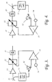
- the basic components of the feed-forward and feed-back regulation configurations are depicted respectively in Figures 3 and 4; In each case an optical tap 30 taps a small proportion of the optical power flowing through the amplifier and feeds it via an optical filter 31 to a photodetector 32. The output of the photodetector is fed to a differential amplifier 33 where it is compared with a reference level applied to terminal 34. The output of the differential amplifier is then applied as a control signal regulating the optical attenuation provided by the attenuator 22.
- the amplifier module 13 is specifically depicted with its attenuator 22 located downstream of its optical waveguide amplifier 21.
- This may be considered the preferred arrangement because the input optical signal power to the module is typically quite low, and hence it is generally preferable, having regard to signal-to-noise considerations, to amplify the input signal before attenuating it rather than performing these operations in the reverse order.
- module power output considerations it may be seen as desirable for the output of the module to be taken direct from the output of its optical waveguide amplifier rather than from that of its attenuator.
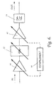
- the basic elements of this amplifier module of Figure 5 comprise, connected optically in cascade, a first fixed gain rare-earth doped optical waveguide amplifier 51, a variable attenuation optical attenuator 52, and a second fixed gain rare-earth doped optical waveguide amplifier 53.
- the attenuator 52 of Figure 5 performs the same function as the attenuator 22 of Figure 2, and so these attenuators may be identical.
- the waveguide amplifiers 51 and 53 are typically doped with erbium.
- the module of Figure 5 may additionally include a filter 54 to perform a gain-flattening function like that performed by filter 23 of the module of Figure 2.
- the filter 54 though represented separately from the waveguide optical amplifiers 51 and 53 in Figure 5 as a single integer, in practice may be constituted in two parts, one incorporated within each of those amplifiers 51 and 53.
- the conditions of operation may change so much as to make it desirable to be able to alter the gain of the upstream waveguide amplifier 51, increasing its gain if the level of input signal power is particularly low, or decreasing it if the level is so high as to run the risk of producing saturation effects in the waveguide amplifier.
- this is entirely possible, provided that a complementary adjustment is made to the gain of the other waveguide amplifier, This complementary adjustment is such that if the gain at some wavelength, ⁇ 1 , of the waveguide amplifier 51 is change by some factor, k, then the gain at wavelength, ⁇ 1 , of waveguide amplifier 53 must be changed by the factor, 1/k.
- Figure 6 depicts the amplifier module of Figure 5 modified by the replacement of the fixed gain waveguide amplifiers 51 and 53 by variable gain waveguide amplifiers 61 and 63. These variable gain waveguide amplifiers are depicted as being indirectly ganged via an element 64 that functions to provide the requisite complementary relationship between the values of gains at wavelength, ⁇ 1 , that they provide.
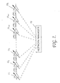
- the partitioning of the aggregate gain between these individual modules can be changed to suit changes in operating conditions without changing the overall gain spectrum of the concatenation. This partitioning is effected under the control of a network manager 70.
Landscapes
- Physics & Mathematics (AREA)
- Electromagnetism (AREA)
- Engineering & Computer Science (AREA)
- Computer Networks & Wireless Communication (AREA)
- Signal Processing (AREA)
- Plasma & Fusion (AREA)
- Optics & Photonics (AREA)
- Lasers (AREA)
- Optical Communication System (AREA)
Abstract
Claims (26)
- Un module amplificateur optique ayant en série au point de vue optique :dans lequel une régulation'du gain global du module amplificateur optique à une longueur d'onde particulière est produite par une régulation de l'atténuation optique produite par l'atténuateur optique variable (52).au moins deux amplificateurs optiques (51, 53, 61, 63) adaptés collectivement pour fournir un niveau prédéterminé de gain agrégé, chaque amplificateur optique présentant une inclinaison de gain dynamique dans des conditions de fonctionnement à gain variable; etun atténuateur optique à atténuation variable (52);
- Un module amplificateur optique selon la revendication 1, dans lequel les au moins deux amplificateurs optiques (51, 53, 61, 63) comprennent deux amplificateurs optiques.
- Un module amplificateur optique selon la revendication 1 ou 2, dans lequel l'atténuateur optique variable (52) est placé en aval de l'un au moins des aux moins deux amplificateurs optiques (51, 53, 61, 63), et dans lequel le signal de sortie du module amplificateur optique est pris à la sortie de l'un des aux moins deux amplificateurs optiques (53, 63) se trouvant en aval de l'atténuateur optique variable (52).
- Un module amplificateur optique selon l'une quelconque des revendications précédentes, dans lequel l'atténuateur optique (52) régule le spectre de gain global du module amplificateur optique.
- Un module amplificateur optique selon l'une quelconque des revendications 1 à 4, dans lequel chaque amplificateur optique (51, 53, 61, 63) comprend un amplificateur optique dopé par une terre rare.
- Un module amplificateur optique selon l'une quelconque des revendications précédentes, dans lequel le niveau prédéterminé de gain agrégé est obtenu par le fait que chaque amplificateur optique (51, 53, 61, 63) fournit un niveau de gain prédéterminé fixé.
- Un module amplificateur optique selon l'une quelconque des revendications 1 à 5, dans lequel les au moins deux amplificateurs optiques (51, 53, 61, 63) comprennent au moins deux amplificateurs optiques à gain variable (61, 63) et le module amplificateur optique comprend en outre un élément de commande de gain (64) adapté pour répartir le gain entre les au moins deux amplificateurs optiques à gain variable (61, 63) à une longueur d'onde donnée, pour maintenir constant le gain agrégé du module amplificateur optique à la longueur d'onde donnée.
- Un module amplificateur optique selon l'une quelconque des revendications précédentes, comprenant en outre un filtre passif de nivelage de gain (54) adapté pour accomplir une fonction de nivelage de gain sur la caractéristique de gain spectrale du gain agrégé fourni par les au moins deux amplificateurs optiques (51, 53, 61, 63).
- Un module amplificateur optique selon la revendication 8, dans lequel le filtre (23, 54) est constitué de parties incorporées à l'intérieur de chacun des amplificateurs optiques (51, 53, 61, 63).
- Un module amplificateur optique selon l'une quelconque des revendications précédentes, dans lequel l'atténuateur optique variable (23, 52) peut être commandé de façon électronique.
- Un module amplificateur optique selon la revendication 1, dans lequel le module a un spectre de gain dans lequel un élargissement homogène est dominant, et dans lequel l'atténuateur optique variable (52) comprend au moins une région produisant une perte, la perte produite par l'au moins une région produisant une perte étant pratiquement uniforme sur le spectre de gain et pouvant être changée électriquement, et dans lequel le module amplificateur comprend un élément de régulation de gain (64) adapté pour maintenir pratiquement constante la caractéristique de gain spectrale du module amplificateur en maintenant pratiquement constant, à une longueur d'onde sélectionnée à l'intérieur du spectre de gain du module amplificateur, le gain agrégé de la totalité des aux moins deux amplificateurs optiques (61, 63) du module amplificateur.
- Un module amplificateur optique selon la revendication 11, dans lequel les au moins deux amplificateurs optiques (61, 63) consistent en deux amplificateurs optiques, et l'atténuateur optique variable (52) est placé au point de vue optique entre les deux amplificateurs optiques (61, 63).
- Un procédé pour faire fonctionner un module amplificateur optique selon la revendication 1 ou 11, le procédé comprenant les étapes suivantes :on commande collectivement les au moins deux amplificateurs optiques (61, 63) pour produire un niveau de gain agrégé prédéterminé constant; eton fait varier l'atténuation optique produite par l'atténuateur optique variable (52) pour réguler le gain global du module amplificateur optique.
- Un procédé selon la revendication 13, dans lequel dans l'étape consistant à faire varier l'atténuation optique, on régule le spectre de gain global du module amplificateur optique.
- Un procédé selon la revendication 13 ou 14, dans lequel dans l'étape de régulation de l'atténuation optique, on commande la régulation de façon électronique.
- Un procédé selon la revendication 13 dans le cas où on fait fonctionner un module amplificateur selon la revendication 11, ce procédé pour faire fonctionner le module amplificateur étant un procédé dans lequel on maintient pratiquement l'invariance de la caractéristique de gain spectrale du module amplificateur en maintenant pratiquement constant, à une longueur d'onde sélectionnée à l'intérieur du spectre de gain du module amplificateur, le gain agrégé de toutes les régions produisant un gain du module amplificateur.
- Une concaténation d'au moins deux modules amplificateurs optiques, selon l'une quelconque des revendications 1 à 12, dans laquelle le gain agrégé enchaíné de la concaténation de modules amplificateurs optiques est maintenu à un niveau prédéterminé.
- Un procédé de commande du gain agrégé enchaíné d'une concaténation d'une multiplicité de modules amplificateurs optiques selon la revendication 17, dans lequel chaque module amplificateur optique comprend les éléments suivants, disposés en série au point de vue optique : au moins deux amplificateurs optiques adaptés collectivement pour produire un niveau de gain agrégé prédéterminé constant, chaque amplificateur optique présentant une inclinaison de gain dans des conditions de fonctionnement à gain variable; et un atténuateur optique à atténuation variable;
dans lequel la régulation du gain global du module amplificateur optique est produite par la régulation de l'atténuation optique produite par l'atténuateur optique variable, le procédé comprenant l'étape suivante :on répartit les gains agrégés entre des modules optiques individuels de la multiplicité de modules optiques, pour maintenir à un niveau prédéterminé le spectre de gain global de la concaténation. - Un système de transmission multiplexé en longueur d'onde ayant une concaténation de modules amplificateurs optiques selon la revendication 17 dans une voie de transmission entre un émetteur et un récepteur, dans lequel chacun des modules amplificateurs de la concaténation est un module amplificateur optique selon l'une quelconque des revendications 10 ou 11.
- Un système multiplexé en longueur d'onde ayant une concaténation de modules amplificateurs optiques selon la revendication 19, dans lequel le système comprend en outre un gestionnaire de réseau adapté pour commander la répartition du gain agrégé produit par les au moins deux modules amplificateurs optiques, pour maintenir au niveau prédéterminé le spectre de gain global de la concaténation.
- Un système de transmission multiplexé en longueur d'onde selon la revendication 19, comprenant en outre :un émetteur à multiplexage en longueur d'onde (10) adapté pour lancer dans une voie de transmission à fibre optique une multiplicité de signaux optiques multiplexés en longueur d'onde;un récepteur à multiplexage en longueur d'onde (12) adapté pour détecter la multiplicité de signaux optiques multiplexés en longueur d'onde à l'extrémité distante de la voie de transmission; dans lequelune multiplicité de modules amplificateurs optiques sont disposés à des intervalles espacés le long de la voie de transmission.
- Un système de transmission multiplexé en longueur d'onde selon la revendication 20, dans lequel la valeur agrégée enchaínée des gains globaux des modules amplificateurs optiques est maintenue à un niveau prédéterminé.
- Un système de transmission multiplexé en longueur d'onde selon la revendication 22, dans lequel le spectre de gain global de la concaténation de modules amplificateurs optiques est maintenu en répartissant le gain agrégé entre des modules amplificateurs optiques individuels.
- Un système de transmission multiplexé en longueur d'onde selon la revendication 19, dans lequel la concaténation comprend un moyen de régulation de gain adapté pour maintenir pratiquement constante, en présence de changements dans la répartition du gain entre les modules amplificateurs optiques de la concaténation, la caractéristique de gain spectrale de la concaténation, en maintenant pratiquement constant, à une longueur d'onde sélectionnée à l'intérieur du spectre de gain des modules amplificateurs, le gain agrégé de tous les amplificateurs optiques de la concaténation.
- Un procédé d'amplification par un module amplificateur d'un trafic multiplexé en longueur d'onde optique transmis le long d'une voie de transmission d'un émetteur vers un récepteur, dans un système de transmission multiplexé en longueur d'onde, dans lequel, dans le module, le trafic est traité en succession par le module premièrement pour l'amplifier une première fois en utilisant un premier amplificateur à guide d'ondes optique à gain fixe (51, 61), puis pour l'atténuer d'une quantité qui est variable, et ensuite pour l'amplifier une seconde fois en utilisant un second amplificateur à guide d'ondes optique à gain fixe (53, 63), dopé par une terre rare, dans lequel les premier et second amplificateurs (51, 53, 61, 63) sont des amplificateurs qui, dans des conditions de fonctionnement à gain variable, présentent une inclinaison du gain.
- Un système de transmission multiplexé en longueur d'onde ayant un émetteur optique (10) en couplage optique avec un récepteur optique (12) par l'intermédiaire d'une voie de transmission qui comprend une concaténation de modules amplificateurs optiques selon la revendication 17, la concaténation ayant un spectre de gain dans lequel un élargissement homogène est dominant, chacun contenant au moins une région produisant un gain optique (21, 51, 53, 61, 63) et au moins une région produisant une perte (22, 52), qui produit une perte qui est pratiquement uniforme sur le spectre de gain des régions produisant un gain, et qui peut être changée de façon électrique, employant un procédé pour faire fonctionner la concaténation pour lui donner une caractéristique de gain spectrale pratiquement invariante en régulant le gain des modules amplificateurs de la concaténation, à une longueur d'onde sélectionnée à l'intérieur du spectre de gain de la concaténation, de façon à maintenir le gain agrégé de toutes les régions de la concaténation produisant un gain optique, en présence de changements dans la répartition du gain entre les modules amplificateurs individuels de la concaténation.
Applications Claiming Priority (3)
| Application Number | Priority Date | Filing Date | Title |
|---|---|---|---|
| GB9613413A GB2314714B (en) | 1996-06-26 | 1996-06-26 | Optical amplifier modules |
| GB9613413 | 1996-06-26 | ||
| PCT/GB1997/001701 WO1997050157A1 (fr) | 1996-06-26 | 1997-06-25 | Modules d'amplificateurs optiques |
Publications (2)
| Publication Number | Publication Date |
|---|---|
| EP0907993A1 EP0907993A1 (fr) | 1999-04-14 |
| EP0907993B1 true EP0907993B1 (fr) | 2003-07-30 |
Family
ID=10795928
Family Applications (1)
| Application Number | Title | Priority Date | Filing Date |
|---|---|---|---|
| EP97928354A Expired - Lifetime EP0907993B1 (fr) | 1996-06-26 | 1997-06-25 | Modules d'amplificateurs optiques |
Country Status (6)
| Country | Link |
|---|---|
| US (2) | US6483632B1 (fr) |
| EP (1) | EP0907993B1 (fr) |
| JP (1) | JP2000513144A (fr) |
| DE (1) | DE69723841T2 (fr) |
| GB (1) | GB2314714B (fr) |
| WO (1) | WO1997050157A1 (fr) |
Families Citing this family (35)
| Publication number | Priority date | Publication date | Assignee | Title |
|---|---|---|---|---|
| US6369938B1 (en) | 1996-05-28 | 2002-04-09 | Fujitsu Limited | Multi-wavelength light amplifier |
| JP3458885B2 (ja) | 1996-11-11 | 2003-10-20 | 住友電気工業株式会社 | 光ファイバ増幅器 |
| SE509968C2 (sv) * | 1997-02-14 | 1999-03-29 | Ericsson Telefon Ab L M | Optisk förstärkare med variabel förstärkning |
| US5900969A (en) * | 1997-02-14 | 1999-05-04 | Lucent Technologies Inc. | Broadband flat gain optical amplifier |
| EP0883255A3 (fr) * | 1997-06-05 | 2002-01-09 | Nortel Networks Limited | Système de transmission WDM avec amplificateurs optiques |
| FR2773425B1 (fr) * | 1998-01-08 | 2000-02-04 | Alsthom Cge Alcatel | Amplificateur optique a excursion de gain optimale pour differentes puissances d'entree |
| JP3779054B2 (ja) | 1998-01-23 | 2006-05-24 | 富士通株式会社 | 可変光学フィルタ |
| JP3638777B2 (ja) | 1998-02-04 | 2005-04-13 | 富士通株式会社 | 利得等化のための方法並びに該方法の実施に使用する装置及びシステム |
| US6603596B2 (en) | 1998-03-19 | 2003-08-05 | Fujitsu Limited | Gain and signal level adjustments of cascaded optical amplifiers |
| US6061171A (en) * | 1998-05-22 | 2000-05-09 | Ciena Corporation | Optical amplifier having a variable attenuator controlled based on input power |
| US6057959A (en) * | 1998-05-22 | 2000-05-02 | Ciena Corporation | Optical amplifier having substantially uniform spectral gain |
| US5963361A (en) * | 1998-05-22 | 1999-10-05 | Ciena Corporation | Optical amplifier having a variable attenuator controlled based on detected ASE |
| CN1310872A (zh) * | 1998-06-19 | 2001-08-29 | 朗迅科技公司 | 掺铒光纤放大器中有中间级衰减器的增益倾斜控制 |
| US6687461B1 (en) * | 1998-11-04 | 2004-02-03 | Board Of Regents, The University Of Texas System | Active optical lattice filters |
| GB2386777A (en) * | 2002-03-19 | 2003-09-24 | Bookham Technology Plc | Polarisation insensitive optical amplifier |
| US20030185485A1 (en) * | 2002-03-27 | 2003-10-02 | Bennett Kevin W. | Optical processing module |
| KR100442658B1 (ko) * | 2002-08-14 | 2004-08-02 | 삼성전자주식회사 | 파장분할다중 광통신 시스템의 광원 발생장치 |
| EP1420491A3 (fr) * | 2002-11-18 | 2005-04-27 | Fujitsu Limited | Amplificateur optique et procédé de réglage d'un amplificateur optique |
| US20040197105A1 (en) * | 2003-02-14 | 2004-10-07 | Jds Uniphase Corporation | Variable gain multi-stage optical amplifier |
| US7054059B1 (en) | 2003-05-14 | 2006-05-30 | Cisco Technoloy, Inc. | Lumped Raman amplification structure for very wideband applications |
| US7483205B1 (en) * | 2003-05-29 | 2009-01-27 | Ciena Corporation | Transient optical power suppressing apparatus, method, and network |
| US7599629B2 (en) * | 2003-06-06 | 2009-10-06 | Scientific-Atlanta, Inc. | Optical receiver having an open loop automatic gain control circuit |
| US7042657B2 (en) * | 2003-08-28 | 2006-05-09 | Board Of Regents The University Of Texas System | Filter for selectively processing optical and other signals |
| KR100581058B1 (ko) * | 2003-09-19 | 2006-05-22 | 한국전자통신연구원 | 광섬유 증폭기 |
| US7324268B2 (en) * | 2003-11-21 | 2008-01-29 | Bti Photonic Systems Inc. | Optical signal amplifier and method |
| WO2006050186A2 (fr) * | 2004-10-29 | 2006-05-11 | Unopsys, Llc | Article comprenant un systeme de transmission optique amplifiee a canaux multiples avec des capacites de valorisation fonctionnelle et des modules universels |
| KR100714102B1 (ko) * | 2005-09-13 | 2007-05-02 | 한국전자통신연구원 | 채널 출력 평탄화 기능을 가지는 광증폭 장치 |
| US7856073B2 (en) * | 2005-12-14 | 2010-12-21 | Sigma Tel, Inc. | Digital gain adjustment in a wireless receiver |
| JP5331950B2 (ja) * | 2006-03-31 | 2013-10-30 | 株式会社メガオプト | 光ファイバレーザ光源 |
| US8098424B2 (en) * | 2006-03-31 | 2012-01-17 | Sumitomo Electric Industries, Ltd. | Optical fiber amplifying module |
| JP5239223B2 (ja) * | 2007-06-21 | 2013-07-17 | 富士通株式会社 | 光増幅器 |
| WO2011026502A1 (fr) * | 2009-09-04 | 2011-03-10 | Nokia Siemens Networks Oy | Amplificateur à fibre optique comprenant un filtre intégré et procédé de commande avec performances améliorées de commande directe |
| JP5811546B2 (ja) * | 2011-02-23 | 2015-11-11 | 富士通株式会社 | 光受信装置および光増幅装置 |
| US20130343751A1 (en) * | 2012-06-23 | 2013-12-26 | Pavel Mamyshev | Optical Receiver with a Wide Power Sensitivity Dynamic Range |
| CN116780317A (zh) * | 2023-04-24 | 2023-09-19 | 中国科学院上海光学精密机械研究所 | 一种硅基掺铒光波导放大器 |
Family Cites Families (26)
| Publication number | Priority date | Publication date | Assignee | Title |
|---|---|---|---|---|
| US5099489A (en) * | 1989-09-15 | 1992-03-24 | At&T Bell Laboratories | Apparatus comprising a quantum well device |
| JPH03206427A (ja) * | 1990-01-08 | 1991-09-09 | Mitsubishi Electric Corp | ファイバ形光増幅器 |
| US5115338A (en) * | 1990-05-30 | 1992-05-19 | At&T Bell Laboratories | Multi-stage optical amplifier |
| US5050949A (en) * | 1990-06-22 | 1991-09-24 | At&T Bell Laboratories | Multi-stage optical fiber amplifier |
| US5187610A (en) * | 1991-12-19 | 1993-02-16 | At&T Bell Laboratories | Low noise, optical amplifier having post-amplification loss element |
| JPH05343784A (ja) * | 1992-06-09 | 1993-12-24 | Nippon Telegr & Teleph Corp <Ntt> | 光増幅器 |
| JPH0653588A (ja) * | 1992-07-31 | 1994-02-25 | Nec Corp | 光ファイバアンプ |
| JPH07281219A (ja) * | 1994-04-14 | 1995-10-27 | Matsushita Electric Ind Co Ltd | 光ファイバ増幅器 |
| PE41196A1 (es) * | 1994-07-25 | 1996-12-17 | Pirelli Cavi Spa | Sistema de telecomunicacion amplificado para transmisiones en multiplex por division de longitud de onda, capaz de limitar las variaciones en la potencia de salida |
| US6400497B1 (en) * | 1994-11-16 | 2002-06-04 | Oki Electric Industry Co., Ltd. | Optical fiber amplifier |
| JPH08248455A (ja) * | 1995-03-09 | 1996-09-27 | Fujitsu Ltd | 波長多重用光増幅器 |
| JPH09191303A (ja) * | 1996-01-09 | 1997-07-22 | Kokusai Denshin Denwa Co Ltd <Kdd> | 光伝送路 |
| JP3730299B2 (ja) | 1996-02-07 | 2005-12-21 | 富士通株式会社 | 光等化増幅器および光等化増幅方法 |
| US6025947A (en) * | 1996-05-02 | 2000-02-15 | Fujitsu Limited | Controller which controls a variable optical attenuator to control the power level of a wavelength-multiplexed optical signal when the number of channels are varied |
| JPH09321701A (ja) * | 1996-05-31 | 1997-12-12 | Fujitsu Ltd | 光通信システム及び光増幅器 |
| US5764406A (en) * | 1996-10-01 | 1998-06-09 | Corning Incorporated | Hydrid optical amplifier having improved dynamic gain tilt |
| SE509968C2 (sv) * | 1997-02-14 | 1999-03-29 | Ericsson Telefon Ab L M | Optisk förstärkare med variabel förstärkning |
| US5900969A (en) * | 1997-02-14 | 1999-05-04 | Lucent Technologies Inc. | Broadband flat gain optical amplifier |
| WO1998036479A1 (fr) * | 1997-02-18 | 1998-08-20 | Nippon Telegraph And Telephone Corporation | Amplificateur optique et systeme de transmission l'utilisant |
| US6049418A (en) * | 1998-02-06 | 2000-04-11 | Lucent Technologies, Inc. | Noise figure in optical amplifiers with a split-band architecture |
| US6049413A (en) * | 1998-05-22 | 2000-04-11 | Ciena Corporation | Optical amplifier having first and second stages and an attenuator controlled based on the gains of the first and second stages |
| US6061171A (en) * | 1998-05-22 | 2000-05-09 | Ciena Corporation | Optical amplifier having a variable attenuator controlled based on input power |
| JP3740849B2 (ja) * | 1998-07-13 | 2006-02-01 | 日立電線株式会社 | 光増幅器 |
| JP3134854B2 (ja) * | 1998-09-07 | 2001-02-13 | 日本電気株式会社 | 光増幅器 |
| US6236499B1 (en) * | 1999-04-15 | 2001-05-22 | Nortel Networks Limited | Highly scalable modular optical amplifier based subsystem |
| US6215584B1 (en) * | 1999-05-10 | 2001-04-10 | Jds Uniphase Inc. | Input independent tilt free actively gain flattened broadband amplifier |
-
1996
- 1996-06-26 GB GB9613413A patent/GB2314714B/en not_active Revoked
-
1997
- 1997-06-25 JP JP10502547A patent/JP2000513144A/ja active Pending
- 1997-06-25 US US09/214,248 patent/US6483632B1/en not_active Expired - Lifetime
- 1997-06-25 DE DE69723841T patent/DE69723841T2/de not_active Expired - Lifetime
- 1997-06-25 WO PCT/GB1997/001701 patent/WO1997050157A1/fr not_active Ceased
- 1997-06-25 EP EP97928354A patent/EP0907993B1/fr not_active Expired - Lifetime
-
2002
- 2002-07-30 US US10/209,625 patent/US6894829B2/en not_active Expired - Lifetime
Also Published As
| Publication number | Publication date |
|---|---|
| DE69723841D1 (de) | 2003-09-04 |
| GB9613413D0 (en) | 1996-08-28 |
| JP2000513144A (ja) | 2000-10-03 |
| EP0907993A1 (fr) | 1999-04-14 |
| US20020196528A1 (en) | 2002-12-26 |
| WO1997050157A1 (fr) | 1997-12-31 |
| GB2314714B (en) | 2000-04-05 |
| GB2314714A (en) | 1998-01-07 |
| US6483632B1 (en) | 2002-11-19 |
| US6894829B2 (en) | 2005-05-17 |
| DE69723841T2 (de) | 2004-03-04 |
Similar Documents
| Publication | Publication Date | Title |
|---|---|---|
| EP0907993B1 (fr) | Modules d'amplificateurs optiques | |
| US6215584B1 (en) | Input independent tilt free actively gain flattened broadband amplifier | |
| US6151157A (en) | Dynamic optical amplifier | |
| US6611371B2 (en) | Single parameter gain slope adjuster for an optical system | |
| EP1909414B1 (fr) | Compensation dynamique de l'inclinaison Raman | |
| EP0859435B1 (fr) | Règlage de la longueur d'onde de pompage dans des amplificateurs optiques et son utilisation dans des systèmes à multiplexage en longueur d'onde | |
| EP1037337B1 (fr) | Amplificateur optique | |
| US6421167B1 (en) | Multiple function bandwidth management systems | |
| US6421170B1 (en) | Gain control and shaping of EDFAs via dual cavity gain control | |
| US6757099B2 (en) | Optical power transient control scheme for EDFA amplifiers | |
| RU2176433C1 (ru) | Способ установки значений опрокидывания и уровня оптических сигналов | |
| US6791745B2 (en) | Optical communication system | |
| US7158288B2 (en) | Long-wavelength-band gain-controlled optical amplifier | |
| US6917467B2 (en) | Optical amplifier | |
| JP3740849B2 (ja) | 光増幅器 | |
| US6151156A (en) | Optical fibre amplifier and transmission system with optical fibre-amplifier | |
| TW369613B (en) | Pump wavelength tuning of optical amplifiers and use of same in wavelength division multiplexed systems | |
| WO1999000924A1 (fr) | Amplificateur optique dynamique | |
| JP2000156671A (ja) | 複数の増幅器を有するwdm伝送システム | |
| WO2002080318A1 (fr) | Commande de gain a compensation de bruit pour amplificateur optique |
Legal Events
| Date | Code | Title | Description |
|---|---|---|---|
| PUAI | Public reference made under article 153(3) epc to a published international application that has entered the european phase |
Free format text: ORIGINAL CODE: 0009012 |
|
| 17P | Request for examination filed |
Effective date: 19990126 |
|
| AK | Designated contracting states |
Kind code of ref document: A1 Designated state(s): DE FR GB |
|
| RAP3 | Party data changed (applicant data changed or rights of an application transferred) |
Owner name: NORTEL NETWORKS CORPORATION |
|
| 17Q | First examination report despatched |
Effective date: 19990713 |
|
| RAP1 | Party data changed (applicant data changed or rights of an application transferred) |
Owner name: NORTEL NETWORKS LIMITED |
|
| RIC1 | Information provided on ipc code assigned before grant |
Free format text: 7H 01S 3/06 A, 7H 01S 3/131 B, 7H 04B 10/17 B, 7H 04J 14/02 B |
|
| GRAH | Despatch of communication of intention to grant a patent |
Free format text: ORIGINAL CODE: EPIDOS IGRA |
|
| RIC1 | Information provided on ipc code assigned before grant |
Free format text: 7H 01S 3/06 A, 7H 01S 3/131 B, 7H 04B 10/17 B, 7H 04J 14/02 B |
|
| GRAH | Despatch of communication of intention to grant a patent |
Free format text: ORIGINAL CODE: EPIDOS IGRA |
|
| GRAA | (expected) grant |
Free format text: ORIGINAL CODE: 0009210 |
|
| AK | Designated contracting states |
Designated state(s): DE FR GB |
|
| REG | Reference to a national code |
Ref country code: GB Ref legal event code: FG4D |
|
| REF | Corresponds to: |
Ref document number: 69723841 Country of ref document: DE Date of ref document: 20030904 Kind code of ref document: P |
|
| RAP2 | Party data changed (patent owner data changed or rights of a patent transferred) |
Owner name: NORTEL NETWORKS LIMITED |
|
| ET | Fr: translation filed | ||
| PLBE | No opposition filed within time limit |
Free format text: ORIGINAL CODE: 0009261 |
|
| STAA | Information on the status of an ep patent application or granted ep patent |
Free format text: STATUS: NO OPPOSITION FILED WITHIN TIME LIMIT |
|
| 26N | No opposition filed |
Effective date: 20040504 |
|
| REG | Reference to a national code |
Ref country code: FR Ref legal event code: TP |
|
| REG | Reference to a national code |
Ref country code: DE Ref legal event code: R082 Ref document number: 69723841 Country of ref document: DE Representative=s name: KUDLEK & GRUNERT PATENTANWAELTE, DE |
|
| REG | Reference to a national code |
Ref country code: DE Ref legal event code: R082 Ref document number: 69723841 Country of ref document: DE Representative=s name: KUDLEK & GRUNERT PATENTANWAELTE PARTNERSCHAFT, DE Effective date: 20120116 Ref country code: DE Ref legal event code: R082 Ref document number: 69723841 Country of ref document: DE Representative=s name: KUDLEK & GRUNERT PATENTANWAELTE PARTNERSCHAFT, DE Effective date: 20120209 Ref country code: DE Ref legal event code: R081 Ref document number: 69723841 Country of ref document: DE Owner name: CIENA LUXEMBOURG S.A.R.L., LU Free format text: FORMER OWNER: NORTEL NETWORKS LTD., MONTREAL, QUEBEC, CA Effective date: 20120209 |
|
| REG | Reference to a national code |
Ref country code: FR Ref legal event code: PLFP Year of fee payment: 19 |
|
| REG | Reference to a national code |
Ref country code: FR Ref legal event code: PLFP Year of fee payment: 20 |
|
| PGFP | Annual fee paid to national office [announced via postgrant information from national office to epo] |
Ref country code: GB Payment date: 20160622 Year of fee payment: 20 Ref country code: DE Payment date: 20160622 Year of fee payment: 20 |
|
| PGFP | Annual fee paid to national office [announced via postgrant information from national office to epo] |
Ref country code: FR Payment date: 20160516 Year of fee payment: 20 |
|
| REG | Reference to a national code |
Ref country code: DE Ref legal event code: R071 Ref document number: 69723841 Country of ref document: DE |
|
| REG | Reference to a national code |
Ref country code: GB Ref legal event code: PE20 Expiry date: 20170624 |
|
| PG25 | Lapsed in a contracting state [announced via postgrant information from national office to epo] |
Ref country code: GB Free format text: LAPSE BECAUSE OF EXPIRATION OF PROTECTION Effective date: 20170624 |