EP0908335A1 - Dispositif de réglage du niveau pour véhicules à ressorts pneumatiques - Google Patents
Dispositif de réglage du niveau pour véhicules à ressorts pneumatiques Download PDFInfo
- Publication number
- EP0908335A1 EP0908335A1 EP98113554A EP98113554A EP0908335A1 EP 0908335 A1 EP0908335 A1 EP 0908335A1 EP 98113554 A EP98113554 A EP 98113554A EP 98113554 A EP98113554 A EP 98113554A EP 0908335 A1 EP0908335 A1 EP 0908335A1
- Authority
- EP
- European Patent Office
- Prior art keywords
- air
- control
- air dryer
- line
- directional valve
- Prior art date
- Legal status (The legal status is an assumption and is not a legal conclusion. Google has not performed a legal analysis and makes no representation as to the accuracy of the status listed.)
- Withdrawn
Links
- 230000008929 regeneration Effects 0.000 description 10
- 238000011069 regeneration method Methods 0.000 description 10
- 238000011161 development Methods 0.000 description 5
- 230000018109 developmental process Effects 0.000 description 5
- 238000010981 drying operation Methods 0.000 description 2
- 238000005429 filling process Methods 0.000 description 2
- 238000012423 maintenance Methods 0.000 description 2
- 238000012549 training Methods 0.000 description 2
- 230000001934 delay Effects 0.000 description 1
- 238000013461 design Methods 0.000 description 1
- 238000001035 drying Methods 0.000 description 1
- 238000004519 manufacturing process Methods 0.000 description 1
- 238000000034 method Methods 0.000 description 1
- 230000003068 static effect Effects 0.000 description 1
- 238000013022 venting Methods 0.000 description 1
Images



Classifications
-
- F—MECHANICAL ENGINEERING; LIGHTING; HEATING; WEAPONS; BLASTING
- F15—FLUID-PRESSURE ACTUATORS; HYDRAULICS OR PNEUMATICS IN GENERAL
- F15B—SYSTEMS ACTING BY MEANS OF FLUIDS IN GENERAL; FLUID-PRESSURE ACTUATORS, e.g. SERVOMOTORS; DETAILS OF FLUID-PRESSURE SYSTEMS, NOT OTHERWISE PROVIDED FOR
- F15B21/00—Common features of fluid actuator systems; Fluid-pressure actuator systems or details thereof, not covered by any other group of this subclass
- F15B21/04—Special measures taken in connection with the properties of the fluid
- F15B21/045—Compensating for variations in viscosity or temperature
-
- B—PERFORMING OPERATIONS; TRANSPORTING
- B60—VEHICLES IN GENERAL
- B60G—VEHICLE SUSPENSION ARRANGEMENTS
- B60G17/00—Resilient suspensions having means for adjusting the spring or vibration-damper characteristics, for regulating the distance between a supporting surface and a sprung part of vehicle or for locking suspension during use to meet varying vehicular or surface conditions, e.g. due to speed or load
- B60G17/015—Resilient suspensions having means for adjusting the spring or vibration-damper characteristics, for regulating the distance between a supporting surface and a sprung part of vehicle or for locking suspension during use to meet varying vehicular or surface conditions, e.g. due to speed or load the regulating means comprising electric or electronic elements
- B60G17/0152—Resilient suspensions having means for adjusting the spring or vibration-damper characteristics, for regulating the distance between a supporting surface and a sprung part of vehicle or for locking suspension during use to meet varying vehicular or surface conditions, e.g. due to speed or load the regulating means comprising electric or electronic elements characterised by the action on a particular type of suspension unit
- B60G17/0155—Resilient suspensions having means for adjusting the spring or vibration-damper characteristics, for regulating the distance between a supporting surface and a sprung part of vehicle or for locking suspension during use to meet varying vehicular or surface conditions, e.g. due to speed or load the regulating means comprising electric or electronic elements characterised by the action on a particular type of suspension unit pneumatic unit
-
- B—PERFORMING OPERATIONS; TRANSPORTING
- B60—VEHICLES IN GENERAL
- B60G—VEHICLE SUSPENSION ARRANGEMENTS
- B60G17/00—Resilient suspensions having means for adjusting the spring or vibration-damper characteristics, for regulating the distance between a supporting surface and a sprung part of vehicle or for locking suspension during use to meet varying vehicular or surface conditions, e.g. due to speed or load
- B60G17/02—Spring characteristics, e.g. mechanical springs and mechanical adjusting means
- B60G17/04—Spring characteristics, e.g. mechanical springs and mechanical adjusting means fluid spring characteristics
- B60G17/052—Pneumatic spring characteristics
- B60G17/0523—Regulating distributors or valves for pneumatic springs
-
- B—PERFORMING OPERATIONS; TRANSPORTING
- B60—VEHICLES IN GENERAL
- B60G—VEHICLE SUSPENSION ARRANGEMENTS
- B60G2202/00—Indexing codes relating to the type of spring, damper or actuator
- B60G2202/10—Type of spring
- B60G2202/15—Fluid spring
- B60G2202/152—Pneumatic spring
-
- B—PERFORMING OPERATIONS; TRANSPORTING
- B60—VEHICLES IN GENERAL
- B60G—VEHICLE SUSPENSION ARRANGEMENTS
- B60G2400/00—Indexing codes relating to detected, measured or calculated conditions or factors
- B60G2400/70—Temperature of vehicle part or in the vehicle
- B60G2400/71—Temperature of vehicle part or in the vehicle of suspension unit
- B60G2400/712—Temperature of vehicle part or in the vehicle of suspension unit of spring
-
- B—PERFORMING OPERATIONS; TRANSPORTING
- B60—VEHICLES IN GENERAL
- B60G—VEHICLE SUSPENSION ARRANGEMENTS
- B60G2500/00—Indexing codes relating to the regulated action or device
- B60G2500/02—Supply or exhaust flow rates; Pump operation
-
- B—PERFORMING OPERATIONS; TRANSPORTING
- B60—VEHICLES IN GENERAL
- B60G—VEHICLE SUSPENSION ARRANGEMENTS
- B60G2500/00—Indexing codes relating to the regulated action or device
- B60G2500/20—Spring action or springs
-
- B—PERFORMING OPERATIONS; TRANSPORTING
- B60—VEHICLES IN GENERAL
- B60G—VEHICLE SUSPENSION ARRANGEMENTS
- B60G2500/00—Indexing codes relating to the regulated action or device
- B60G2500/20—Spring action or springs
- B60G2500/201—Air spring system type
- B60G2500/2012—Open systems
-
- B—PERFORMING OPERATIONS; TRANSPORTING
- B60—VEHICLES IN GENERAL
- B60G—VEHICLE SUSPENSION ARRANGEMENTS
- B60G2500/00—Indexing codes relating to the regulated action or device
- B60G2500/20—Spring action or springs
- B60G2500/202—Height or leveling valve for air-springs
- B60G2500/2021—Arrangement of valves
-
- B—PERFORMING OPERATIONS; TRANSPORTING
- B60—VEHICLES IN GENERAL
- B60G—VEHICLE SUSPENSION ARRANGEMENTS
- B60G2500/00—Indexing codes relating to the regulated action or device
- B60G2500/20—Spring action or springs
- B60G2500/204—Pressure regulating valves for air-springs
-
- B—PERFORMING OPERATIONS; TRANSPORTING
- B60—VEHICLES IN GENERAL
- B60G—VEHICLE SUSPENSION ARRANGEMENTS
- B60G2500/00—Indexing codes relating to the regulated action or device
- B60G2500/20—Spring action or springs
- B60G2500/204—Pressure regulating valves for air-springs
- B60G2500/2042—Air filling valves
-
- B—PERFORMING OPERATIONS; TRANSPORTING
- B60—VEHICLES IN GENERAL
- B60G—VEHICLE SUSPENSION ARRANGEMENTS
- B60G2500/00—Indexing codes relating to the regulated action or device
- B60G2500/20—Spring action or springs
- B60G2500/204—Pressure regulating valves for air-springs
- B60G2500/2044—Air exhausting valves
-
- B—PERFORMING OPERATIONS; TRANSPORTING
- B60—VEHICLES IN GENERAL
- B60G—VEHICLE SUSPENSION ARRANGEMENTS
- B60G2500/00—Indexing codes relating to the regulated action or device
- B60G2500/30—Height or ground clearance
-
- B—PERFORMING OPERATIONS; TRANSPORTING
- B60—VEHICLES IN GENERAL
- B60G—VEHICLE SUSPENSION ARRANGEMENTS
- B60G2600/00—Indexing codes relating to particular elements, systems or processes used on suspension systems or suspension control systems
- B60G2600/08—Failure or malfunction detecting means
Definitions
- Such a level control device for vehicles with air springs is, for example, from the US-PS 44 64 297 known.
- a Air dryer To fill up the air spring, this is via a Air dryer, a check valve and an electrically controllable first directional valve a compressed air source connected, the air dryer when filling the air spring in Drying operation is operated.
- the air spring When the air spring is emptied, it is over the first electrically controllable directional valve, a throttle, the air dryer and a second one electrically controllable directional valve connected to the atmosphere, whereby when emptying the air spring of the air dryer is operated in regeneration mode.
- the invention has for its object to provide a level control device for vehicles To create air springs in which a good regeneration of the Air dryer is possible.
- this is pneumatically controllable Directional valve arranged between the compressed air source and the air dryer, and connects in the compressed air source with the air dryer in the first switching state and in the second Switching state the atmosphere with the air dryer.
- a level control device which is a pneumatic Controllable directional valve between the compressed air source and the air dryer, which in a first switching state connects the compressed air source with the air dryer and in one second switching state connects the atmosphere with the air dryer.
- the pneumatic controllable directional valve however, has only one control line.
- a second embodiment of the invention bridges the pressurizable line in which the pneumatically controllable directional valve is arranged is the air dryer, d. that is, the pressurizable line branches between the Compressed air source and the air dryer and ends behind the air dryer again on one Line leading to the air springs.
- the advantage of this embodiment is there too see that when filling the air springs, the air directly from the compressed air source in the Air dryer passes, and not, as in the first embodiment, via the pneumatic controllable directional valve is guided.
- the pneumatically controllable directional valve only Air is discharged from the air springs into the atmosphere after it has been released Air dryer has passed.
- there is no moisture Air in the pneumatically controllable directional valve so that the risk of icing of the Valve is reduced.
- the level control device according to the second Build up a simpler constructive setup.
- control line of the first Control input via a controllable 3/2-way valve in a first switching position with the Atmosphere or in a second switching position with the pressurizable line connectable.
- the Control line of the first control input two parts, of which the first part on the leads first control input and via a controllable 2/2-way valve directly with the Atmosphere is connectable and the second part with a throttle pressurized line is connectable.
- a residual pressure control valve over which the air spring is connected to the air dryer for emptying.
- Residual pressure maintenance valve designed as a controllable residual pressure maintenance valve.
- the pressurized line to which the free ends of the control line lead Air dryer with the pneumatically controllable directional valve In this case, the Control inputs of the pneumatically controllable valve in the basic state of Level control device with the air pressure applied to the compressed air source facing the entrance of the air dryer.
- the advantage of this training is there too see that a compact design is possible.
- FIG. 1 shows a schematic representation of a level control device for a vehicle Air springs 8, wherein the controllable directional valves 18 and 30 are switched so that the Level control device in the basic state (first in the introduction to the description Switching state) (i.e. the air springs 8 are neither filled nor emptied).
- the basic state the same air pressure is present at the control inputs 20 and 22 which in itself can be provided by any source.
- the pressurized line 40 between the pneumatically controllable directional valve 18 and the air dryer 6 connected so that the control inputs 20 and 22 in the basic state then with the air pressure be acted upon at the inlet 32 of the compressor 4 facing the Air dryer 6 is applied.
- the pneumatically controllable directional valve 18 is through the Return spring 24 stably fixed in the basic state.
- the pneumatically controllable directional valve 18 on the side of the control input 20 through the Return spring 24 is applied, but it is also possible to use it on the side of the Actuate control input 22 by the return spring 24.
- the control unit 2 sends a control signal to the Control input 14 of the compressor 4, whereupon it begins to run.
- the air spring 8 is then via the pneumatically controllable directional valve 18, the air dryer 6 and that Check valve 10 filled.
- the air dryer 6 runs in the drying operation.
- a signal is again sent from the control unit 2 to the control input 14 of the compressor 4, whereupon the latter stops running.
- the controllable directional valves 18 and 30 take the same position as in the basic state.
- the control input 2 of the control unit 2 electrically controllable 3/2-way valve so that this is different from that in FIG shown switching state changes into the other switching state.
- This control line 26 of the first control input 20 of the pneumatically controllable directional valve 18 is then with the Atmosphere connected, so that the pressure drops in the control line 26. Because in the Control line 28 of the second control input 22 of the pneumatically controllable directional valve 18 the pressure does not drop (note that the 3/2-way valve also in the other Switching state blocks the control line 28 to the atmosphere), this becomes pneumatic controllable directional valve 18 against the restoring force of the return spring 24 from that in the Figure 1 switching state transferred to the other switching state.
- the air spring 8 is then via the throttle 16, the residual pressure control valve 12 and the air dryer 6 with the Atmosphere connected. When emptying the air spring 8, the air dryer 6 is in the Regeneration operation operated. The air spring 8 can only be emptied up to a residual pressure be specified by the controllable residual pressure control valve 12.
- the control unit 2 does so electrically controllable 3/2-way valve 30 is de-energized, so that it in turn is in the Figure 1 assumes the switching state shown.
- the control line 26 of the first control input 20 same air pressure as in the control line 28 of the second control input 22, so that on the control inputs 20 and 22 pressure equilibrium prevails.
- the pneumatically controllable directional valve 18 then goes into the in the figure 1 switching state shown.
- the level control device is again in the Basic state and is ready for refilling or emptying the air spring 8.
- the directional valve 18 Since the directional valve 18 is designed as a pneumatically controllable directional valve, it can have a high flow cross section and as a result the air dryer 6 can be quickly vented in regeneration mode. So even with unfavorable ones Operating conditions of the level control device a good regeneration of the air dryer 6 guaranteed.
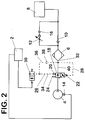
- FIG. 2 shows a level control device for vehicles with air springs 8, which largely is constructed in exactly the same way as the level control device shown in FIG. Only the Structure between the compressor 4 and the air dryer 6 is different.
- the controllable directional control valves 18 and 30 are so switched that the level control device assumes its basic state. Filling the Air spring 8 with the help of the compressor 4 happens exactly as it is already in the Has been described in connection with Figure 1, so that not yet at this point to be discussed once.
- the control unit 2 does so electrically controllable directional valve 30 is initially de-energized, so that this in turn assumes the switching state shown in FIG. 2.
- the first control line 26 the same air pressure as in the second control line 28, so that the same air pressures act on the control inputs 20 and 22. Due to the The pneumatically controllable directional valve 18 then takes the restoring force of the return spring 24 again the switching state shown in Figure 2 and the level control device goes back to its normal state.
- FIG. 3 shows a schematic representation of a level control device for a Vehicle with air springs 8, the controllable directional valves 18 and 30 being switched that the level control device in the basic state (in the introduction to the description as first switching state)) (i.e. the air springs 8 are neither filled nor emptied).
- the air dryer 6 is through bridges the pressurizable line 40, d. H. the pressurizable line 40 branches at a point 42 which lies between the compressor 4 and the air dryer 6, from the line leading to the air springs 8 and is behind the air dryer 6 in a point 44 again on the line leading to the air springs 8.
- the control valves 18 and 30 are the control valves 18 and 30.
- Die Control inputs 20 and 22 of the pneumatically controllable directional valve 18 are over Control lines 26 and 28 connected to the pressurizable line 40.
- the Basic state of the level control device is at the control inputs 20 and 22 of the same air pressure and the pneumatically controllable directional valve 18 is by the Return spring 24 stably fixed in the basic state (i.e. in the first switching state).
- the control unit 2 sends a control signal to the Control input 14 of the compressor, whereupon it begins to run.
- the air spring 8 will then filled via the air dryer 6 and the check valve 10.
- the filling process is to be ended, it is issued again a signal from the control unit 2 to the control input 14 of the compressor, whereupon this stops running.
- the control unit 2 takes the controllable Directional control valves 18 and 30 enter the basic state shown in the figure. Furthermore, at Filling the air spring only air from the compressor 4 via the air dryer 6 and the check valve 10 is guided into the air spring 8.
- a guide of the air from that Compressor 4 via the pressurizable line 40 which bridges the air dryer 6, is not possible because the pneumatically controllable directional valve 18 is designed so that a Air flow from the part of the pressurizable part facing the compressor 4 Line 40 to the part of the pressurizable line 40 facing the air spring 8 is excluded (indicated by the arrow in the upper box of the pneumatic controllable directional valve 18, which points from the air spring 8 in the direction of the compressor 4; the same applies to the controllable directional valve 30).
- the control input 2 of the control unit 2 electrically controllable 3/2-way valve 30, so that this of the in the figure 3 switching state shown in the other switching state.
- the control line 26 of the first control input 20 of the pneumatically controllable directional valve 18 is then with the Atmosphere connected, so that the pressure drops in the control line 26. Because in the Control line 28 of the second control input 22 of the pneumatically controllable directional valve 18 the pressure does not drop (note that the 3/2-way valve also in the other Switching state blocks the control line 28 to the atmosphere), this becomes pneumatic controllable directional valve 18 against the restoring force of the return spring 24 from that in the Figure 3 switching state transferred to the other switching state.
- the air spring 8 is then via the throttle 16, the residual pressure control valve 12 and the air dryer 6 and that pneumatically controllable directional valve 18 connected to the atmosphere.
- the air dryer is also operated here in the regeneration mode.
- the air spring 8 can only be emptied up to a residual pressure, which can be adjusted by the adjustable Residual pressure holding valve 12 is specified.
- the control unit 2 does so electrically controllable 3/2-way valve 30 is de-energized, so that it in turn Figure 3 assumes the switching state.
- the same air pressure is in the control line 26 of the first control input 20 as in the control line 28 of the second control input 22, so that at the Control inputs 20 and 22 pressure balance prevails.
- the pneumatically controllable directional valve 18 then goes into the in the figure 3 switching state shown above.
- the level control device is again in the Basic state and is ready for refilling or emptying the air spring 8.
- the branch 44 in which the pressurizable line 40 ends between the air dryer 6 and the Check valve 10.
- Basic state of the level control device is at the control inputs 20 and 22 of the pneumatically controllable directional valve 18 to the pressure of the air spring 8.
- the pneumatic controllable directional valve 18 can thus by means of the air pressure of the air spring in the FIG. 3 shows the first switching state shown in the second switching state, if the control line 26 with the help of the controllable directional valve 30 to the atmosphere is vented (see above).
- first switching state When switching from the second switching state to the in the Figure 3 shown first switching state must be at the control input 20 of the pneumatic controllable directional valve 18 only build up a pressure that is sufficiently large to Directional control valve 18 from the second switching state using the air pressure and the Return spring 24 in the first switching state. This can be due to the Throttle 16, at which the pressure drops from the air spring 8, takes a period of time take, which delays the switching process.
Landscapes
- Engineering & Computer Science (AREA)
- Mechanical Engineering (AREA)
- Chemical & Material Sciences (AREA)
- Analytical Chemistry (AREA)
- Physics & Mathematics (AREA)
- Fluid Mechanics (AREA)
- General Engineering & Computer Science (AREA)
- Vehicle Body Suspensions (AREA)
Applications Claiming Priority (2)
| Application Number | Priority Date | Filing Date | Title |
|---|---|---|---|
| DE19745195 | 1997-10-13 | ||
| DE19745195A DE19745195C2 (de) | 1997-10-13 | 1997-10-13 | Niveauregeleinrichtung für Fahrzeuge mit Luftfedern |
Publications (1)
| Publication Number | Publication Date |
|---|---|
| EP0908335A1 true EP0908335A1 (fr) | 1999-04-14 |
Family
ID=7845415
Family Applications (1)
| Application Number | Title | Priority Date | Filing Date |
|---|---|---|---|
| EP98113554A Withdrawn EP0908335A1 (fr) | 1997-10-13 | 1998-07-21 | Dispositif de réglage du niveau pour véhicules à ressorts pneumatiques |
Country Status (3)
| Country | Link |
|---|---|
| US (1) | US6116586A (fr) |
| EP (1) | EP0908335A1 (fr) |
| DE (1) | DE19745195C2 (fr) |
Cited By (2)
| Publication number | Priority date | Publication date | Assignee | Title |
|---|---|---|---|---|
| CN102307648A (zh) * | 2009-01-28 | 2012-01-04 | 大陆-特韦斯贸易合伙股份公司及两合公司 | 用于控制车辆的封闭式行驶高度调节系统中的空气干燥器的再生循环的方法 |
| WO2012079680A1 (fr) * | 2010-12-16 | 2012-06-21 | Wabco Gmbh | Dessiccateur d'air pneumatique |
Families Citing this family (21)
| Publication number | Priority date | Publication date | Assignee | Title |
|---|---|---|---|---|
| DE19835491C2 (de) * | 1998-08-06 | 2000-05-25 | Continental Ag | Niveauregeleinrichtung für Fahrzeuge mit Luftfedern |
| DE19918157C1 (de) * | 1999-04-22 | 2000-10-26 | Continental Ag | Niveauregeleinrichtung für Fahrzeuge mit Luftfedern |
| DE10055108A1 (de) * | 2000-11-07 | 2002-05-08 | Daimler Chrysler Ag | Luftfederung mit geschlossenem Druckluftsystem |
| EP1243447B1 (fr) * | 2001-03-24 | 2005-12-21 | Continental Aktiengesellschaft | Dispositif fermé de réglage du niveau pour véhicules |
| DE10231251C1 (de) * | 2002-07-11 | 2003-08-14 | Continental Ag | Geschlossene Niveauregelanlage mit zwei Druckspeichern für Fahrzeuge |
| DE10240357B4 (de) * | 2002-09-02 | 2016-10-06 | Wabco Gmbh | Luftfederungsanlage für ein Fahrzeug |
| DE10240358A1 (de) * | 2002-09-02 | 2004-03-11 | Wabco Gmbh & Co. Ohg | Luftfederungsanlage für ein Fahrzeug |
| DE10240359A1 (de) * | 2002-09-02 | 2004-03-11 | Wabco Gmbh & Co. Ohg | Luftfederungsanlage für ein Fahrzeug |
| US8306696B2 (en) * | 2003-04-17 | 2012-11-06 | Driveright Holdings, Ltd. | Method and system for aligning a vehicle with an artificial horizon |
| PL1615787T3 (pl) * | 2003-04-17 | 2010-03-31 | Firestone Ind Products Co Llc | Sposób i układ do wyrównywania nieruchomego pojazdu względem sztucznego horyzontu |
| DE10342120A1 (de) | 2003-09-10 | 2005-04-28 | Continental Ag | Verfahren zur Messung eines Drucks, Niveauregelanlage und Ventil |
| ATE482341T1 (de) * | 2004-11-03 | 2010-10-15 | Wabco Gmbh | Gewinde für eine schraubverbindung |
| US7744099B2 (en) * | 2004-11-04 | 2010-06-29 | Driveright Holdings, Ltd. | Method and system for adjusting a vehicle aligned with an artificial horizon |
| US8155835B2 (en) * | 2008-02-21 | 2012-04-10 | Driveright Holdings, Ltd. | Vehicle chassis height adjustment method and system |
| DE102009029898A1 (de) * | 2009-06-23 | 2010-12-30 | Wabco Gmbh | Druckluftversorgungssystem für einen Druckluftverbraucherkreis, insbesondere für ein Luftfederungssystem |
| DE102012001734B4 (de) * | 2012-01-31 | 2020-11-12 | Wabco Gmbh | Druckluftversorgungsanlage, pneumatisches System und Verfahren zum Betreiben einer Druckluftversorgungsanlage bzw. eines pneumatischen Systems |
| DE102012001736A1 (de) * | 2012-01-31 | 2013-08-01 | Wabco Gmbh | Druckluftversorgungsanlage, pneumatisches System und Verfahren zum Betreiben einer Druckluftversorgungsanlage bzw. eines pneumatischen Systems |
| US9101519B2 (en) | 2013-02-07 | 2015-08-11 | Dallas Smith Corporation | Leveling ramp for a wheelchair |
| JP6475179B2 (ja) | 2016-03-14 | 2019-02-27 | アイシン精機株式会社 | 車高制御システム |
| JP6378228B2 (ja) * | 2016-03-14 | 2018-08-22 | トヨタ自動車株式会社 | 車高調整システム |
| WO2026060018A1 (fr) | 2024-09-11 | 2026-03-19 | Gilead Sciences, Inc. | Obeldesivir pour le traitement d'infections virales |
Citations (10)
| Publication number | Priority date | Publication date | Assignee | Title |
|---|---|---|---|---|
| US4464297A (en) | 1981-07-29 | 1984-08-07 | Sumitomo Chemical Company, Limited | Fiber reactive bisazo dye having both a vinylsulfone type reactive group and an ortho-nitrophenyl group |
| US4465297A (en) | 1981-12-17 | 1984-08-14 | Aisin Seiki Kabushiki Kaisha | Vehicle height control apparatus |
| EP0165376A2 (fr) * | 1984-06-22 | 1985-12-27 | WABCO Westinghouse Fahrzeugbremsen GmbH | Système pneumatique à haute pression avec deux circuits à pression différente |
| EP0224663A2 (fr) * | 1985-12-05 | 1987-06-10 | WABCO Westinghouse Fahrzeugbremsen GmbH | Dispositif de réglage du niveau de véhicules à ressorts à gaz |
| EP0400301A2 (fr) * | 1989-05-30 | 1990-12-05 | WABCO Vermögensverwaltungs-GmbH | Dispositif de réglage d'assiette pour véhicules |
| DE3919438A1 (de) * | 1989-06-14 | 1990-12-20 | Wabco Westinghouse Fahrzeug | Druckluftbetaetigbare einrichtung mit einem zwischen einer druckmittelquelle und verbrauchern befindlichem lufttrockner |
| DE4235111A1 (de) * | 1992-10-17 | 1994-04-21 | Bayerische Motoren Werke Ag | Ventilanordnung für Pneumatikleitungen |
| DE4327763A1 (de) * | 1993-08-18 | 1995-02-23 | Bosch Gmbh Robert | Luftfederungsanlage |
| DE19528852A1 (de) * | 1995-08-05 | 1997-02-06 | Continental Ag | Niveauregeleinrichtung |
| DE19724747C1 (de) | 1997-06-12 | 1998-06-25 | Continental Ag | Niveauregeleinrichtung für Fahrzeuge mit Luftfedern |
Family Cites Families (7)
| Publication number | Priority date | Publication date | Assignee | Title |
|---|---|---|---|---|
| US4826141A (en) * | 1987-04-20 | 1989-05-02 | Toyota Jidosha Kabushiki Kaisha | Electronic controlled air suspension system |
| DE4012251C1 (fr) * | 1990-04-14 | 1991-07-11 | Grau Gmbh, 6900 Heidelberg, De | |
| GB9119534D0 (en) * | 1991-09-13 | 1991-10-23 | Dunlop Ltd | Vehicle suspension system |
| GB9213268D0 (en) * | 1992-06-23 | 1992-08-05 | Rover Group | A suspension system for a vehicle |
| JP3296868B2 (ja) * | 1993-02-05 | 2002-07-02 | アイシン精機株式会社 | 車高調整装置 |
| DE19527937C2 (de) * | 1995-07-29 | 1999-11-04 | Continental Ag | Restdruckhalteventil für eine Luftfederung |
| DE19603593C1 (de) * | 1996-02-01 | 1997-04-30 | Daimler Benz Ag | Pneumatisches bzw. hydropneumatisches Federungssystem |
-
1997
- 1997-10-13 DE DE19745195A patent/DE19745195C2/de not_active Expired - Fee Related
-
1998
- 1998-07-21 EP EP98113554A patent/EP0908335A1/fr not_active Withdrawn
- 1998-10-09 US US09/168,970 patent/US6116586A/en not_active Expired - Fee Related
Patent Citations (10)
| Publication number | Priority date | Publication date | Assignee | Title |
|---|---|---|---|---|
| US4464297A (en) | 1981-07-29 | 1984-08-07 | Sumitomo Chemical Company, Limited | Fiber reactive bisazo dye having both a vinylsulfone type reactive group and an ortho-nitrophenyl group |
| US4465297A (en) | 1981-12-17 | 1984-08-14 | Aisin Seiki Kabushiki Kaisha | Vehicle height control apparatus |
| EP0165376A2 (fr) * | 1984-06-22 | 1985-12-27 | WABCO Westinghouse Fahrzeugbremsen GmbH | Système pneumatique à haute pression avec deux circuits à pression différente |
| EP0224663A2 (fr) * | 1985-12-05 | 1987-06-10 | WABCO Westinghouse Fahrzeugbremsen GmbH | Dispositif de réglage du niveau de véhicules à ressorts à gaz |
| EP0400301A2 (fr) * | 1989-05-30 | 1990-12-05 | WABCO Vermögensverwaltungs-GmbH | Dispositif de réglage d'assiette pour véhicules |
| DE3919438A1 (de) * | 1989-06-14 | 1990-12-20 | Wabco Westinghouse Fahrzeug | Druckluftbetaetigbare einrichtung mit einem zwischen einer druckmittelquelle und verbrauchern befindlichem lufttrockner |
| DE4235111A1 (de) * | 1992-10-17 | 1994-04-21 | Bayerische Motoren Werke Ag | Ventilanordnung für Pneumatikleitungen |
| DE4327763A1 (de) * | 1993-08-18 | 1995-02-23 | Bosch Gmbh Robert | Luftfederungsanlage |
| DE19528852A1 (de) * | 1995-08-05 | 1997-02-06 | Continental Ag | Niveauregeleinrichtung |
| DE19724747C1 (de) | 1997-06-12 | 1998-06-25 | Continental Ag | Niveauregeleinrichtung für Fahrzeuge mit Luftfedern |
Cited By (3)
| Publication number | Priority date | Publication date | Assignee | Title |
|---|---|---|---|---|
| CN102307648A (zh) * | 2009-01-28 | 2012-01-04 | 大陆-特韦斯贸易合伙股份公司及两合公司 | 用于控制车辆的封闭式行驶高度调节系统中的空气干燥器的再生循环的方法 |
| CN102307648B (zh) * | 2009-01-28 | 2014-03-19 | 大陆-特韦斯贸易合伙股份公司及两合公司 | 用于控制车辆的封闭式行驶高度调节系统中的空气干燥器的再生循环的方法 |
| WO2012079680A1 (fr) * | 2010-12-16 | 2012-06-21 | Wabco Gmbh | Dessiccateur d'air pneumatique |
Also Published As
| Publication number | Publication date |
|---|---|
| US6116586A (en) | 2000-09-12 |
| DE19745195C2 (de) | 2000-11-02 |
| DE19745195A1 (de) | 1999-04-22 |
Similar Documents
| Publication | Publication Date | Title |
|---|---|---|
| DE19745195C2 (de) | Niveauregeleinrichtung für Fahrzeuge mit Luftfedern | |
| EP0978397B1 (fr) | Dispositif de réglage du niveau pour véhicules à ressorts pneumatiques | |
| EP0884203B1 (fr) | Dispositif de réglage du niveau pour véhicules à ressorts à gaz | |
| DE10231251C1 (de) | Geschlossene Niveauregelanlage mit zwei Druckspeichern für Fahrzeuge | |
| DE19918157C1 (de) | Niveauregeleinrichtung für Fahrzeuge mit Luftfedern | |
| DE3542975C2 (fr) | ||
| DE3919438C2 (de) | Druckluftbetätigbare Einrichtung mit einem zwischen einer Druckmittelquelle und Verbrauchern befindlichem Lufttrockner | |
| EP0304610A2 (fr) | Dispositif de soupape à réglage | |
| DE1108090B (de) | Selbsttaetig arbeitende Luftsteuervorrichtung zur Erhaltung der Bodenfreiheit von Fahrzeugen mit pneumatischen oder hydraulisch-pneumatischen Federungen | |
| DE2510954C2 (de) | Luftfederung für Kraftfahrzeuge, insbesondere für Containerfahrzeuge | |
| DE2619775C2 (fr) | ||
| EP0165376B1 (fr) | Système pneumatique à haute pression avec deux circuits à pression différente | |
| DE2514257C3 (de) | Bremseinrichtung für Fahrzeuge, insbesondere Schienenfahrzeuge | |
| EP0415009A2 (fr) | Dispositif de freinage, notamment pour véhicules ferroviaires | |
| EP0005304A2 (fr) | Dispositif pneumatique de freinage pour véhicules | |
| EP0175108B1 (fr) | Suspension à gaz pour véhicules, en particulier pour véhicules ferroviaires | |
| EP0385162B1 (fr) | Frein à air comprimé à action indirecte en fonction de la charge pour véhicules ferroviaires avec un convertisseur de pression | |
| EP0592388B1 (fr) | Système de réglage de la pression de la suspension transversale entre le bogie et la caisse de véhicules ferroviaires | |
| DE2302185C3 (de) | Dreikreisbremsventil für Straßenfahrzeuge | |
| DE3734618C1 (en) | Manually operatable axle lifting valve for multi-axle motor vehicles, trailer vehicles and the like | |
| EP0339660B1 (fr) | Dispositif pour basculer un ensemble disposé sur un véhicule | |
| DE102006032348A1 (de) | Ventilanordnung für eine Fahrzeug-Luftfederung sowie Ventilblock | |
| DE1006736B (de) | Steuerventil fuer lastabhaengige Regelung des Bremszylinder-Druckes in Druckluft-Bremsanlagen von Fahrzeugen, insbesondere von Anhaengerfahrzeugen des Strassenverkehrs | |
| DE1220465B (de) | Schalteinrichtung fuer umschaltbare Bremsgestaenge von Eisenbahn-Druckluftbremsen | |
| DE2151027A1 (de) | Pruefeinrichtung zum pruefen der funktionsfaehigkeit eines bremskraftreglers, insbesondere fuer strassenfahrzeuge |
Legal Events
| Date | Code | Title | Description |
|---|---|---|---|
| PUAI | Public reference made under article 153(3) epc to a published international application that has entered the european phase |
Free format text: ORIGINAL CODE: 0009012 |
|
| AK | Designated contracting states |
Kind code of ref document: A1 Designated state(s): AT DE FR GB SE |
|
| AX | Request for extension of the european patent |
Free format text: AL;LT;LV;MK;RO;SI |
|
| 17P | Request for examination filed |
Effective date: 19991014 |
|
| AKX | Designation fees paid |
Free format text: AT DE FR GB SE |
|
| GRAG | Despatch of communication of intention to grant |
Free format text: ORIGINAL CODE: EPIDOS AGRA |
|
| GRAG | Despatch of communication of intention to grant |
Free format text: ORIGINAL CODE: EPIDOS AGRA |
|
| GRAH | Despatch of communication of intention to grant a patent |
Free format text: ORIGINAL CODE: EPIDOS IGRA |
|
| 17Q | First examination report despatched |
Effective date: 20010827 |
|
| STAA | Information on the status of an ep patent application or granted ep patent |
Free format text: STATUS: THE APPLICATION IS DEEMED TO BE WITHDRAWN |
|
| 18D | Application deemed to be withdrawn |
Effective date: 20020112 |