EP0224663A2 - Dispositif de réglage du niveau de véhicules à ressorts à gaz - Google Patents
Dispositif de réglage du niveau de véhicules à ressorts à gaz Download PDFInfo
- Publication number
- EP0224663A2 EP0224663A2 EP86112423A EP86112423A EP0224663A2 EP 0224663 A2 EP0224663 A2 EP 0224663A2 EP 86112423 A EP86112423 A EP 86112423A EP 86112423 A EP86112423 A EP 86112423A EP 0224663 A2 EP0224663 A2 EP 0224663A2
- Authority
- EP
- European Patent Office
- Prior art keywords
- pressure
- air spring
- valve
- control device
- directional
- Prior art date
- Legal status (The legal status is an assumption and is not a legal conclusion. Google has not performed a legal analysis and makes no representation as to the accuracy of the status listed.)
- Withdrawn
Links
- 230000008929 regeneration Effects 0.000 claims description 4
- 238000011069 regeneration method Methods 0.000 claims description 4
- 238000001035 drying Methods 0.000 claims description 3
- 230000002950 deficient Effects 0.000 abstract description 2
- 238000006073 displacement reaction Methods 0.000 description 9
- 230000000903 blocking effect Effects 0.000 description 5
- 239000000725 suspension Substances 0.000 description 4
- 238000011156 evaluation Methods 0.000 description 3
- 238000013022 venting Methods 0.000 description 3
- 230000007547 defect Effects 0.000 description 1
- 230000001419 dependent effect Effects 0.000 description 1
- 238000011161 development Methods 0.000 description 1
- 230000018109 developmental process Effects 0.000 description 1
- 238000005429 filling process Methods 0.000 description 1
- 238000000034 method Methods 0.000 description 1
- 230000001105 regulatory effect Effects 0.000 description 1
- 230000001960 triggered effect Effects 0.000 description 1
- 238000011144 upstream manufacturing Methods 0.000 description 1
Images


Classifications
-
- B—PERFORMING OPERATIONS; TRANSPORTING
- B60—VEHICLES IN GENERAL
- B60G—VEHICLE SUSPENSION ARRANGEMENTS
- B60G17/00—Resilient suspensions having means for adjusting the spring or vibration-damper characteristics, for regulating the distance between a supporting surface and a sprung part of vehicle or for locking suspension during use to meet varying vehicular or surface conditions, e.g. due to speed or load
- B60G17/015—Resilient suspensions having means for adjusting the spring or vibration-damper characteristics, for regulating the distance between a supporting surface and a sprung part of vehicle or for locking suspension during use to meet varying vehicular or surface conditions, e.g. due to speed or load the regulating means comprising electric or electronic elements
- B60G17/0152—Resilient suspensions having means for adjusting the spring or vibration-damper characteristics, for regulating the distance between a supporting surface and a sprung part of vehicle or for locking suspension during use to meet varying vehicular or surface conditions, e.g. due to speed or load the regulating means comprising electric or electronic elements characterised by the action on a particular type of suspension unit
- B60G17/0155—Resilient suspensions having means for adjusting the spring or vibration-damper characteristics, for regulating the distance between a supporting surface and a sprung part of vehicle or for locking suspension during use to meet varying vehicular or surface conditions, e.g. due to speed or load the regulating means comprising electric or electronic elements characterised by the action on a particular type of suspension unit pneumatic unit
-
- B—PERFORMING OPERATIONS; TRANSPORTING
- B60—VEHICLES IN GENERAL
- B60G—VEHICLE SUSPENSION ARRANGEMENTS
- B60G17/00—Resilient suspensions having means for adjusting the spring or vibration-damper characteristics, for regulating the distance between a supporting surface and a sprung part of vehicle or for locking suspension during use to meet varying vehicular or surface conditions, e.g. due to speed or load
- B60G17/02—Spring characteristics, e.g. mechanical springs and mechanical adjusting means
- B60G17/04—Spring characteristics, e.g. mechanical springs and mechanical adjusting means fluid spring characteristics
- B60G17/052—Pneumatic spring characteristics
- B60G17/0523—Regulating distributors or valves for pneumatic springs
Definitions
- the invention relates to a level control device for vehicles with air springs according to the preamble of claim 1.
- Load-dependent level control is mainly used for air-sprung vehicles.
- the amount of air in the bellows of the air suspension is regulated depending on the vehicle load so that a predetermined distance of the vehicle cell from the vehicle axle is always the same.
- DE-OS 30 31 453 A device of the type mentioned is known from DE-OS 30 31 453. This known device essentially consists of the following parts:
- a distance measuring device measures the distance between the vehicle cell and the vehicle axis, which changes as a result of loading or unloading the vehicle.
- the measured data are compared with a target value (normal level) by means of an electronic evaluation circuit. If there is a deviation, the normal level is restored by ventilating or venting the air springs.
- the electronics switch an air spring valve between the pressure medium source and the air springs to passage and cause the pressure medium source to convey air into the air springs until the electronics recognize the normal level reported by the position measuring device.
- the air supply is then switched off and the air spring valve is closed.
- the air springs are emptied in such a way that the electronics switch the air spring valve and a second vent valve that opens to the atmosphere to passage.
- the air springs are then emptied into the atmosphere until the electronics shut off both valves when the normal level is recognized.
- the known device has the disadvantage that even when the vehicle cell is lowered as a result of an unauthorized overloading and thus overloading of the vehicle, the pressure medium source is caused by the displacement measuring device and the electronics to restore the normal level, ie to convey air into the bellows of the air springs , although these already have a correspondingly high air pressure due to the overloading of the vehicle.
- the air springs which are filled up with overpressure in this way, are additionally activated during driving dynamic pressure peaks loaded, so that it can damage the air suspension bellows. Switching errors, z. B. by a defective displacement measuring device and / or electronics, such that the pressure medium source is not switched off, can lead to an uncontrolled increase in pressure in the air bellows and thus to the damage mentioned.
- the invention is therefore based on the object of improving the device of the type mentioned in such a way that a predetermined maximum pressure in the bellows of the air springs cannot be exceeded in any load condition of the vehicle and in the event of switching errors in the level control system.
- the invention has the advantage that when the vehicle is overloaded, the vehicle cell can come to rest on a fixed stop of the chassis and in this state does not exceed the predetermined maximum pressure in the bellows of the air suspension with a "low level" recognized by the displacement measuring device and consequently switched on pressure medium source becomes.
- a further advantage results if the level control device is equipped with an air dryer which is operated in the regeneration phase when the air springs are being filled up in the drying phase and when the air springs are emptied, ie when the vehicle cell is lowered.
- the air flowing out of the air springs even when the vehicle is overloaded can then also be passed through the air dryer to regenerate the air dryer. This results in a maximum utilization of the air flowing out of the air springs when the vehicle cell is lowered or when the vehicle is overloaded for the regeneration of the air dryer.
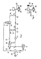
- an air spring 15 which is shown symbolically and includes all the other air springs of the vehicle, for filling with a pressure medium source 5 and for emptying with a first pneumatically controllable and in the atmosphere venting directional valve 19 connectable.
- the first directional valve 19 has a pneumatic control input 18, which can be acted upon by a second controllable directional valve 8 serving as an air spring valve with a control pressure determining the pressure in the air spring 15 against a restoring force 22 acting on the pneumatic control input 18.
- An air dryer 11 can be connected on the one hand via a first check valve 13 opening towards the air spring 15 and on the other hand via a second check valve 23 opening towards the air dryer 11 and via the directional control valve 8 with the air spring 15.
- a throttle 21 is connected upstream of the second check valve 23, via which the second check valve 23 is connected to a pressure medium outlet 34 of the second directional valve 8.
- the pneumatic control input 18 of the first directional control valve 19 is connected to the line connecting the throttle 21 and to a line connecting the pressure medium output 34 of the second directional control valve 8.
- a distance measuring device 1 which measures the distance (the level) of the vehicle cell from the vehicle axis, is connected to an electronic control unit 2 via an electrical line 26.
- An evaluation circuit with a setpoint value which corresponds to a predetermined normal level is integrated in the electronic control unit 2.
- the level measured by the displacement measuring device 1 is compared with the normal level which is stored in the evaluation circuit and which can be changed, if necessary. According to the level comparison, the electronic control unit 2 transmits electrical control signals either via an electrical line 3 to an electrical control connection 4 of the pressure medium source 5 or via a given electrical line 6 to an electrical control connection 7 of the directional valve 8.
- the pressure medium source 5 is switched on by the electronic control unit 2. Air is supplied to the air spring 15 via a pressure line 9, 10, via the air dryer 11, a pressure line 12, the check valve 13 and a pressure line 14 until the normal level is reached and the electronic control unit 2 switches off the pressure medium source 5 again.
- the air spring 15 is emptied into the atmosphere with the pressure medium source 5 switched off until the normal level is reached.
- the electronic control unit 2 switches the air spring valve 8 from the blocking position into the open position.
- the pressure medium flowing out of the air spring 15 passes via the pressure lines 14, 16, 17 to the pneumatic control input 18 of the directional control valve 19, which then switches over to the atmosphere.
- the air spring 15 is then connected to the atmosphere via the pressure line 10, 9 and the first directional valve 19 until the path measuring device 1 signals that the predetermined normal level has been reached and the electronic control unit 2 does so Directional control valve 8 switches back into the blocking position.
- the pressure line 9 is shut off during the emptying of the air spring 15 with respect to the switched off pressure medium source 5.
- the effective pressure at the control input 18 of the directional control valve 19 is then so far to the atmospheric pressure via the connection 17, 20, 11, 10, 9 and the directional control valve 19 adjusted until the restoring force 22 moves the directional valve 19 into the closed position.
- the check valve 23 arranged in the line 20 between the throttle 21 and the air dryer 11 blocks the connection to the control connection 18 of the directional control valve 19 during the filling process.
- the directional control valve 19 is thereby prevented from being switched to the position in the pressure line during the filling phase 9 is connected to the atmosphere.
- a line connection 24 which connects the pressure line 12 to the pressure line 20.
- the pressure lines 12, 14, 16 are connected to one another by a line connection 25.
- the check valve 13 arranged in the line 12 between the line connections 24, 25 blocks the connection of the air spring 15 to the air dryer 11 during the emptying process.
- the air dryer 11 is operated when filling the air spring 15 in the drying mode and when the air spring 15 is emptied in the regeneration mode.
- a suitable air dryer is described in DE-PS 19 47 550.
- the throttle 21 arranged in the pressure line 20 ensures during the emptying phase that, on the one hand, relaxed air is supplied to the air dryer 11 and, on the other hand, an unthrottled control pressure can act at the control input 18.
- the valve device for emptying the air spring 15 into the atmosphere advantageously has a third one, which acts as a safety valve against excess pressure in the air suspension Directional control valve 27, which can be controlled with a pressure corresponding to the pressure in the air spring 15.
- the air spring 15 is emptied via the third directional valve 27 as soon as the pressure in the air spring 15 has reached a pressure level which is above a predetermined maximum operating pressure.
- This pressure level which is above the maximum operating pressure, arises when the vehicle is overloaded and thus overloaded.
- the overload like the normal payload within the specified permissible load limit, causes the vehicle cell to lower.
- the path measuring device 1 registers this change in the level position, but does not recognize that this level change is due to an overload of the vehicle.
- the displacement measuring device 1 consequently causes the pressure medium source 5 to convey air into the air spring 15 via the electronics 2 in order to restore the normal level of the vehicle cell. As a result, the increased air pressure in the air springs 15 due to overloading the vehicle is further increased.
- a critical pressure level could be reached in the air spring 15, which can lead to damage to the bellows of the air spring 15.
- This critical pressure level can be achieved in particular when driving, if the pressure which rises in the air spring 15 above the maximum operating pressure is suddenly increased by dynamic pressure peaks.
- a pressure level in the air spring 15 which exceeds the predetermined maximum operating pressure can also be achieved by switching errors in the level control system if, for. B. by a defect in the measuring device 1 and / or Electronics 2 the pressure medium source 5 is not switched off.
- the directional control valve 27 connected to the air spring 15 has a switching point which is below the critical pressure in the air spring 15, so that a reduction in the pressure in the air spring 15 is triggered before the air spring 15 can be damaged by the circumstances described.
- the directional control valve 27 is connected to the air spring 15 via the line 14.
- the directional control valve 27 has a pneumatic control input 28 which can be acted upon by the pressure prevailing in the air spring 15 via a pressure line 29.
- the directional control valve 27 has an electrical control input 30 which is connected to a pressure sensor 32 via an electrical line 31.
- the pressure sensor 32 measures the pressure present in the air spring 15 and causes the directional control valve 27 to connect the air spring 15 to the atmosphere at a predetermined pressure in the air spring 15.
- a device (not shown), which converts the signal of the pressure sensor 32 into a switching current for the control input 30, is active between the pressure sensor 32 and the electrical control input 30.
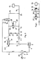
- the directional control valve 27 is connected to the air spring 15 via the line 14 as described in FIG. 1, but the air spring 15 is connected via the directional valve 27 and a pressure line 33 to the one from the pressure outlet 34 of the second directional valve 8 to the control input 18 of the first directional valve 19 leading pressure line connectable.
- the directional control valve 27 is arranged as described in FIG. 3.
- an electrical control input 30 is provided according to the exemplary embodiment according to FIG. 2, which is connected via the electrical line 31 to the pressure sensor 32 measuring the pressure in the air spring 15.
- the third directional control valve 27 and the second directional control valve 8 of the arrangement according to FIG. 1 are combined to form a directional control valve 35 with an electrical control input 7 and a pneumatic control input 28.
- the air spring 15 can be connected via the directional control valve 35 to the pneumatic control input 18 of the first directional control valve 19 and via the air dryer 11 to the outlet to the atmosphere of the first directional control valve 19.
- the electrical control input 7 is controlled in a level control in the sense of lowering the vehicle cell by the displacement measuring device 1 and the electronics 2.
- the pneumatic control input 28 is controlled via a pressure line 29 by a pressure corresponding to the pressure in the air spring 15 in the sense of the overload control mentioned.
- the directional control valve 35 is switched from the blocking position into the through position, whereby a connection from the air spring 15 to the control input 18 and thus to the outlet of the air dryer 11 is produced with the directional valve 19 connecting the atmosphere.
- the electrical control input 7 of the second directional valve 8 is connected on the one hand via the electrical line 6 to the electronics 2 which can be controlled by the displacement measuring device 1 and on the other hand via an electrical line 36 to the pressure sensor 32.
- the control input 7 is only shown in principle by the electronics 2 or by the pressure sensor 32, the directional control valve 8 is switched from the blocking position into the through position, whereby the air spring 15 is emptied as described above with reference to FIG. 5.
- the embodiment according to FIG. 6 has the advantage of less effort compared to the embodiments according to FIGS. 1 to 5, because the second directional valve 8 has only one electrical control input 7 which can be controlled both by the displacement measuring device 1 and by the pressure sensor 32.
- the pressure medium source 5 is not switched off when the vehicle is overloaded, because in such a case the displacement measuring device 1 indicates a low level that would have to be compensated for by filling the air spring 15. Nevertheless, the pressure medium source 5 is protected against delivery, against an undesirable excess pressure in the system, because the pressure medium source 5 and the air spring 15 are connected to the connection to the atmosphere caused by the excess pressure in the air spring 15 via the first directional valve 19.
- the pressure sensor 32 is connected to the electronics 2 via an electrical line 37.
- a setpoint value comparison circuit of the electronics 2 the pressure in the air spring 15 signaled by the pressure sensor 32 is compared with a predetermined setpoint value.
- This setpoint corresponds to a maximum pressure in the air spring 15 achieved by overloading the vehicle, at which the electrical control input 7 of the second directional valve 8 is caused by the electronics 2 via the electrical line 6 to switch the second directional valve 8 from the blocking position into the open position.
- an OR gate of the electronics 2 causes an electrical control input 4 of the pressure medium source 5 via an electrical line 3 to switch off the pressure medium source 5.
- the signal given by the path measuring device 1 to the electronics 2 which corresponds to a low level caused by overloading the vehicle, is suppressed in the electronics 2.
- the described device for protection against exceeding a predetermined maximum pressure in the air spring 15 can also be used in level control devices that are not equipped with an air dryer.
- the air flowing out of the air spring 15 is then, as shown in FIGS. 1 and 2, directed directly into the atmosphere.
- a pressure limiting valve of a conventional type arranged in the pressure line between the pressure medium source 5 and the air spring 15 is used (not shown).
- Such a pressure relief valve would shut off the pressure medium source 5 from the air spring 15 at a predetermined pressure on its secondary side, which would correspond to the pressure in the air spring 15.
- the pressure medium source 5 would then be connected to the atmosphere for the duration of the overload of the air spring 15.
- the pressure in the air spring 15 would increase proportionally to the overloading of the vehicle until the vehicle cell comes to rest on a fixed stop of the chassis, but a further pressure increase in the air spring 15 would not be possible because the pressure medium source 5 in the described switching position of the pressure relief valve is connected to the atmosphere.
Landscapes
- Engineering & Computer Science (AREA)
- Mechanical Engineering (AREA)
- Vehicle Body Suspensions (AREA)
- Fluid-Damping Devices (AREA)
Applications Claiming Priority (2)
| Application Number | Priority Date | Filing Date | Title |
|---|---|---|---|
| DE3542974 | 1985-12-05 | ||
| DE19853542974 DE3542974A1 (de) | 1985-12-05 | 1985-12-05 | Niveauregeleinrichtung fuer fahrzeuge mit luftfedern |
Publications (2)
| Publication Number | Publication Date |
|---|---|
| EP0224663A2 true EP0224663A2 (fr) | 1987-06-10 |
| EP0224663A3 EP0224663A3 (fr) | 1987-11-04 |
Family
ID=6287679
Family Applications (1)
| Application Number | Title | Priority Date | Filing Date |
|---|---|---|---|
| EP86112423A Withdrawn EP0224663A3 (fr) | 1985-12-05 | 1986-09-08 | Dispositif de réglage du niveau de véhicules à ressorts à gaz |
Country Status (4)
| Country | Link |
|---|---|
| US (1) | US4756548A (fr) |
| EP (1) | EP0224663A3 (fr) |
| JP (1) | JPS62134311A (fr) |
| DE (1) | DE3542974A1 (fr) |
Cited By (4)
| Publication number | Priority date | Publication date | Assignee | Title |
|---|---|---|---|---|
| DE3813873A1 (de) * | 1988-04-25 | 1989-11-02 | Freudenberg Carl Fa | Gasdruckfeder |
| EP0884203A1 (fr) * | 1997-06-12 | 1998-12-16 | Continental Aktiengesellschaft | Dispositif de réglage du niveau pour véhicules à ressorts à gaz |
| EP0908335A1 (fr) * | 1997-10-13 | 1999-04-14 | Continental Aktiengesellschaft | Dispositif de réglage du niveau pour véhicules à ressorts pneumatiques |
| WO2001056820A1 (fr) * | 2000-02-04 | 2001-08-09 | Bayerische Motoren Werke Aktiengesellschaft | Systeme d'amortisseur pneumatique pour un vehicule automobile |
Families Citing this family (47)
| Publication number | Priority date | Publication date | Assignee | Title |
|---|---|---|---|---|
| US4902903A (en) * | 1988-10-27 | 1990-02-20 | Segerson Eugene E | Apparatus employing reflective optical means |
| DE3841476A1 (de) * | 1988-12-09 | 1990-06-13 | Bosch Gmbh Robert | Verfahren zur regelung einer druckluftgestuetzten fahrzeugfederung |
| DE3917458A1 (de) * | 1989-05-30 | 1990-12-06 | Wabco Westinghouse Fahrzeug | Niveauregeleinrichtung fuer fahrzeuge |
| US4993729A (en) * | 1989-09-14 | 1991-02-19 | Volvo Gm Heavy Truck Corporation | Vehicle suspension |
| GB9119544D0 (en) * | 1991-09-13 | 1991-10-23 | Dunlop Ltd | Valve means |
| US5267466A (en) * | 1991-09-26 | 1993-12-07 | Ford Motor Co. | Apparatus and method for calibrating a suspension control module |
| DE10007382A1 (de) * | 2000-02-18 | 2001-08-23 | Bayerische Motoren Werke Ag | Luftfedersystem für ein zweiachsiges Kraftfahrzeug |
| DE19539887B4 (de) * | 1995-10-26 | 2008-07-10 | Knorr-Bremse Systeme für Nutzfahrzeuge GmbH | Vorrichtung zur Regelung eines Fahrzeugaufbauniveaus |
| DE19603593C1 (de) * | 1996-02-01 | 1997-04-30 | Daimler Benz Ag | Pneumatisches bzw. hydropneumatisches Federungssystem |
| US5725239A (en) * | 1996-03-26 | 1998-03-10 | Monroe Auto Equipment | Adaptive load dependent suspension system |
| DE19647998A1 (de) * | 1996-11-20 | 1998-05-28 | Duewag Ag | Luftfeder für Schienenfahrzeuge |
| BR9909537A (pt) | 1998-04-07 | 2000-12-12 | P Dennis Mcneely | Suporte ajustável para suportar uma carga dinâmica em relação a uma fundação e processo para suportar uma carga dinâmica que pode se deslocar em relação a uma fundação |
| DE19835491C2 (de) * | 1998-08-06 | 2000-05-25 | Continental Ag | Niveauregeleinrichtung für Fahrzeuge mit Luftfedern |
| DE19848217B4 (de) * | 1998-10-20 | 2013-06-27 | Wabco Gmbh | Gasverdichter |
| DE19902049C2 (de) * | 1999-01-20 | 2000-11-09 | Continental Ag | Niveauregelsystem für ein Kraftfahrzeug |
| US6224069B1 (en) | 1999-02-08 | 2001-05-01 | General Motors Corporation | Body leveling system for motor vehicle |
| DE19918157C1 (de) * | 1999-04-22 | 2000-10-26 | Continental Ag | Niveauregeleinrichtung für Fahrzeuge mit Luftfedern |
| CN100475581C (zh) | 1999-08-24 | 2009-04-08 | 哈尔德克斯制动器公司 | 高度控制阀 |
| AU2002305698B2 (en) * | 2001-05-25 | 2007-06-07 | Haldex Brake Corporation | Trailing arm suspension and height control system with motorized valve therefor |
| US7204478B2 (en) * | 2002-08-07 | 2007-04-17 | Haldex Brake Corporation | Height control valve with universal mounting for a suspension system |
| USD499173S1 (en) | 2002-08-07 | 2004-11-30 | Haldex Brake Corporation | Valve with three mounting holes |
| JP4673079B2 (ja) * | 2005-02-09 | 2011-04-20 | 株式会社日立製作所 | 過荷重検知装置を備えた鉄道車両 |
| US20080252025A1 (en) * | 2007-04-12 | 2008-10-16 | Plath Victor A | Electronic height control system for a vehicle with multiple input signals |
| US10836232B2 (en) | 2007-04-12 | 2020-11-17 | Haldex Brake Products Corporation | Electronic height control system for a vehicle with multiple input signals |
| DE102010052570B4 (de) | 2010-11-25 | 2019-11-28 | Wabco Gmbh | Magnetventil, Druckluftaufbereitungseinrichtung, Verfahren zum Betrieb einer Druckluftaufbereitungseinrichtung, sowie Fahrzeug |
| DE102010054699A1 (de) | 2010-12-16 | 2012-06-21 | Wabco Gmbh | Druckluftversorgungsanlage und pneumatisches System |
| DE102010054712B4 (de) | 2010-12-16 | 2023-06-07 | Zf Cv Systems Hannover Gmbh | Druckluftversorgungsanlage und pneumatisches System |
| DE102010054702A1 (de) | 2010-12-16 | 2012-06-21 | Wabco Gmbh | Pneumatischer Lufttrockner |
| DE102010054705A1 (de) | 2010-12-16 | 2012-06-21 | Wabco Gmbh | Luftfederanlage, Druckluftversorgungsanlage und pneumatisches System |
| DE102010054704A1 (de) | 2010-12-16 | 2012-06-21 | Wabco Gmbh | Druckluftversorgungsanlage und pneumatisches System |
| DE102010054713A1 (de) | 2010-12-16 | 2012-06-21 | Wabco Gmbh | Druckluftversorgungsanlage, pneumatisches System und Verfahren |
| DE102010054709A1 (de) | 2010-12-16 | 2012-06-21 | Wabco Gmbh | Lufttrockner-System, Druckluftversorgungsanlage, pneumatisches System und Verfahren zum Betreiben einer Pneumatikanlage |
| DE102011109500A1 (de) * | 2010-12-16 | 2012-06-21 | Wabco Gmbh | Druckluftversorgungsanlage, pneumatisches System und Verfahren zum Betreiben einer Pneumatikanlage |
| DE102012005345B4 (de) | 2011-12-23 | 2024-02-08 | Zf Cv Systems Hannover Gmbh | Druckluftversorgungsanlage, Druckluftversorgungssystem, Fahrzeug und Verwendung der Druckluftversorgungsanlage |
| WO2014014460A1 (fr) * | 2012-07-19 | 2014-01-23 | Continental Teves Ag & Co. Ohg | Système de ressort pneumatique incorporant une détection de surcharge |
| DE102012024757A1 (de) | 2012-12-19 | 2014-06-26 | Wabco Gmbh | Ringförmiges Dichtungselement, Ventil, Druckluftversorgungsanlage, Druckluftversorgungssystem und Fahrzeug |
| US20160281906A1 (en) * | 2013-09-25 | 2016-09-29 | Bühler AG | Device for treating and/or processing bulk material |
| CN103707902B (zh) * | 2013-11-29 | 2016-04-20 | 北京市地铁运营有限公司地铁运营技术研发中心 | 一种城市轨道交通车辆乘客载荷检测系统及方法 |
| DE102014207509A1 (de) * | 2014-04-17 | 2015-10-22 | Continental Teves Ag & Co. Ohg | Integrierte Luftversorgungseinheit |
| DE102014009419B4 (de) | 2014-06-25 | 2023-06-07 | Zf Cv Systems Hannover Gmbh | Druckluftversorgungsanlage, pneumatisches System und Verfahren zum Steuern einer Druckluftversorgungssanlage |
| DE102014012609B4 (de) | 2014-08-22 | 2023-03-23 | Zf Cv Systems Hannover Gmbh | Druckluftversorgungsanlage, pneumatisches System und Verfahren zum Betreiben einer Pneumatikanlage |
| DE102014012645A1 (de) | 2014-08-22 | 2016-02-25 | Wabco Gmbh | Druckluftversorgungsanlage, pneumatisches System und Verfahren zum Betreiben einer Pneumatikanlage |
| DE102014012608B4 (de) | 2014-08-22 | 2023-03-30 | Zf Cv Systems Hannover Gmbh | Druckluftversorgungsanlage, pneumatisches System und Verfahren zum Betreiben einer Pneumatikanlage |
| DE102014012680B4 (de) | 2014-08-22 | 2023-03-16 | Zf Cv Systems Hannover Gmbh | Pneumatikschaltung für PKW-Luftfederungssystem |
| US10343479B2 (en) | 2014-08-22 | 2019-07-09 | Wabco Gmbh | Pneumatic circuit for passenger car pneumatic suspension system |
| JP6426042B2 (ja) * | 2015-03-27 | 2018-11-21 | 住友重機械工業株式会社 | 空気バネ用空気圧調整ユニット |
| EP4265494B1 (fr) | 2022-04-21 | 2025-07-02 | ZF CV Systems Global GmbH | Unité de traitement d'air, système de gestion d'air, système pneumatique et véhicule |
Family Cites Families (15)
| Publication number | Priority date | Publication date | Assignee | Title |
|---|---|---|---|---|
| DE1430557A1 (de) * | 1963-09-06 | 1969-04-30 | Bosch Gmbh Robert | Ventilvorrichtung |
| US3401948A (en) * | 1966-01-21 | 1968-09-17 | Midland Ross Corp | Vehicle leveling system and control valve |
| US3592563A (en) * | 1968-12-30 | 1971-07-13 | Westinghouse Air Brake Co | Filter purging apparatus |
| DE2012203A1 (de) * | 1970-03-14 | 1971-09-30 | Robert Bosch Gmbh, 7000 Stuttgart | Luftfederungseinrichtung |
| GB1358920A (en) * | 1970-11-18 | 1974-07-03 | Daimler Benz Ag | Pneumatic suspension arrangements in motor vehicles |
| DE2116058C3 (de) * | 1971-04-02 | 1978-09-07 | Robert Bosch Gmbh, 7000 Stuttgart | Elektrisch gesteuerte Niveauregeleinrichtung für Luftfederungen von Fahrzeugen |
| JPS55109196U (fr) * | 1979-01-25 | 1980-07-31 | ||
| JPS5913137Y2 (ja) * | 1979-08-20 | 1984-04-19 | トキコ株式会社 | 車高調整装置 |
| DE3028472C2 (de) * | 1980-07-26 | 1982-08-26 | Daimler-Benz Ag, 7000 Stuttgart | Steuereinrichtung für eine luftgefederte, anhebbare und absenkbare Nachlaufachse eines Nutzkraftfahrzeugs |
| JPS58105814A (ja) * | 1981-12-17 | 1983-06-23 | Aisin Seiki Co Ltd | 車高調整装置 |
| JPS58156783A (ja) * | 1982-03-11 | 1983-09-17 | Honda Motor Co Ltd | 逆止弁 |
| US4568093A (en) * | 1982-12-23 | 1986-02-04 | Honda Giken Kogyo Kabushiki Kaisha | Method of operating vehicle height adjusting apparatus |
| US4558886A (en) * | 1983-09-22 | 1985-12-17 | Straub Gerald J | Fluid circuit means for elevating the rear end of an air ride truck trailer |
| US4570972A (en) * | 1984-05-02 | 1986-02-18 | General Motors Corporation | Pressure control valving for pneumatic leveling systems |
| US4607861A (en) * | 1984-12-17 | 1986-08-26 | General Motors Corporation | Hydraulic stabilizing system for vehicle suspension |
-
1985
- 1985-12-05 DE DE19853542974 patent/DE3542974A1/de not_active Withdrawn
-
1986
- 1986-09-08 EP EP86112423A patent/EP0224663A3/fr not_active Withdrawn
- 1986-10-10 US US06/917,571 patent/US4756548A/en not_active Expired - Lifetime
- 1986-12-04 JP JP61287884A patent/JPS62134311A/ja active Pending
Cited By (7)
| Publication number | Priority date | Publication date | Assignee | Title |
|---|---|---|---|---|
| DE3813873A1 (de) * | 1988-04-25 | 1989-11-02 | Freudenberg Carl Fa | Gasdruckfeder |
| EP0884203A1 (fr) * | 1997-06-12 | 1998-12-16 | Continental Aktiengesellschaft | Dispositif de réglage du niveau pour véhicules à ressorts à gaz |
| US6098967A (en) * | 1997-06-12 | 2000-08-08 | Continental Aktiengesellschaft | Level control arrangement for vehicles having air springs |
| EP0908335A1 (fr) * | 1997-10-13 | 1999-04-14 | Continental Aktiengesellschaft | Dispositif de réglage du niveau pour véhicules à ressorts pneumatiques |
| US6116586A (en) * | 1997-10-13 | 2000-09-12 | Continental Aktiengesellschaft | Level control arrangement for vehicles having air springs |
| WO2001056820A1 (fr) * | 2000-02-04 | 2001-08-09 | Bayerische Motoren Werke Aktiengesellschaft | Systeme d'amortisseur pneumatique pour un vehicule automobile |
| US6726224B2 (en) | 2000-02-04 | 2004-04-27 | Bayerische Motoren Werke Aktiengesellschaft | Pneumatic suspension system for a motor vehicle |
Also Published As
| Publication number | Publication date |
|---|---|
| US4756548A (en) | 1988-07-12 |
| EP0224663A3 (fr) | 1987-11-04 |
| DE3542974A1 (de) | 1987-06-11 |
| JPS62134311A (ja) | 1987-06-17 |
Similar Documents
| Publication | Publication Date | Title |
|---|---|---|
| EP0224663A2 (fr) | Dispositif de réglage du niveau de véhicules à ressorts à gaz | |
| EP0170794B1 (fr) | Dispositif à ressort pneumatique pour véhicules | |
| DE3542975C2 (fr) | ||
| DE19724747C1 (de) | Niveauregeleinrichtung für Fahrzeuge mit Luftfedern | |
| DE19745195C2 (de) | Niveauregeleinrichtung für Fahrzeuge mit Luftfedern | |
| EP2059428A1 (fr) | Système de freinage pneumatique de véhicule, ainsi que procédé de commande d'un tel système de freinage | |
| EP0400301A2 (fr) | Dispositif de réglage d'assiette pour véhicules | |
| EP0447750A1 (fr) | Système de freinage avec au moins un circuit de freinage | |
| EP0199895A2 (fr) | Installation de freinage à milieu sous pression pour la remorque d'un véhicule | |
| DE4027688C2 (de) | Aktives Aufhängungssystem für Kraftfahrzeuge | |
| EP0301225A1 (fr) | Procédé de régulation d'une suspension pneumatique de véhicule | |
| DE3919438A1 (de) | Druckluftbetaetigbare einrichtung mit einem zwischen einer druckmittelquelle und verbrauchern befindlichem lufttrockner | |
| DE2735470C2 (de) | Bremsanlage zum Abbremsen der Räder eines Flugzeuges | |
| DE19544622C1 (de) | Steueranlage für ein luftgefedertes Fahrzeug mit Niveauregelung | |
| DE2460309A1 (de) | Blockierschutzregelsystem fuer druckmittelbetaetigte fahrzeugbremsen | |
| DE2524427A1 (de) | Blockierschutzregelsystem | |
| EP0152958A2 (fr) | Soupape de freinage de conducteur | |
| EP1697193A1 (fr) | Procede pour surveiller la variation du couple de freinage d'un ralentisseur | |
| EP0345203A2 (fr) | Installation de freinage avec moyen de pression régulé électroniquement | |
| DE4004502C2 (fr) | ||
| EP0238891B1 (fr) | Déchargement d'un essieu traîné pour un véhicule à essieux en tandem | |
| DE3101731C2 (fr) | ||
| EP1741578B1 (fr) | Dispositif de commande de système de suspension pneumatique d'un véhicule | |
| DE19514185C1 (de) | Bremsanlage mit lastabhängiger Regelung des Vorderachs-Bremsdruckes von Fahrzeugen, insbesondere von Nutzfahrzeugen | |
| EP0779166A2 (fr) | Dispositif de réglage du niveau |
Legal Events
| Date | Code | Title | Description |
|---|---|---|---|
| PUAI | Public reference made under article 153(3) epc to a published international application that has entered the european phase |
Free format text: ORIGINAL CODE: 0009012 |
|
| AK | Designated contracting states |
Kind code of ref document: A2 Designated state(s): DE IT SE |
|
| PUAL | Search report despatched |
Free format text: ORIGINAL CODE: 0009013 |
|
| AK | Designated contracting states |
Kind code of ref document: A3 Designated state(s): DE IT SE |
|
| 17P | Request for examination filed |
Effective date: 19871016 |
|
| 17Q | First examination report despatched |
Effective date: 19880219 |
|
| STAA | Information on the status of an ep patent application or granted ep patent |
Free format text: STATUS: THE APPLICATION IS DEEMED TO BE WITHDRAWN |
|
| 18D | Application deemed to be withdrawn |
Effective date: 19880630 |
|
| RIN1 | Information on inventor provided before grant (corrected) |
Inventor name: SCHOENFELD, KARL-HEINRICH, DR. ING. Inventor name: KALTENTHALER,WOLFGANG,DIPL.-ING. |