EP0908348A2 - Verfahren zum Bremsen eines elektrisch angetriebenen Fahrzeuges - Google Patents
Verfahren zum Bremsen eines elektrisch angetriebenen Fahrzeuges Download PDFInfo
- Publication number
- EP0908348A2 EP0908348A2 EP98850151A EP98850151A EP0908348A2 EP 0908348 A2 EP0908348 A2 EP 0908348A2 EP 98850151 A EP98850151 A EP 98850151A EP 98850151 A EP98850151 A EP 98850151A EP 0908348 A2 EP0908348 A2 EP 0908348A2
- Authority
- EP
- European Patent Office
- Prior art keywords
- motor
- rotational speed
- brake
- maneuvering means
- activated
- Prior art date
- Legal status (The legal status is an assumption and is not a legal conclusion. Google has not performed a legal analysis and makes no representation as to the accuracy of the status listed.)
- Granted
Links
Images


Classifications
-
- B—PERFORMING OPERATIONS; TRANSPORTING
- B60—VEHICLES IN GENERAL
- B60L—PROPULSION OF ELECTRICALLY-PROPELLED VEHICLES; SUPPLYING ELECTRIC POWER FOR AUXILIARY EQUIPMENT OF ELECTRICALLY-PROPELLED VEHICLES; ELECTRODYNAMIC BRAKE SYSTEMS FOR VEHICLES IN GENERAL; MAGNETIC SUSPENSION OR LEVITATION FOR VEHICLES; MONITORING OPERATING VARIABLES OF ELECTRICALLY-PROPELLED VEHICLES; ELECTRIC SAFETY DEVICES FOR ELECTRICALLY-PROPELLED VEHICLES
- B60L7/00—Electrodynamic brake systems for vehicles in general
- B60L7/24—Electrodynamic brake systems for vehicles in general with additional mechanical or electromagnetic braking
- B60L7/26—Controlling the braking effect
-
- B—PERFORMING OPERATIONS; TRANSPORTING
- B60—VEHICLES IN GENERAL
- B60L—PROPULSION OF ELECTRICALLY-PROPELLED VEHICLES; SUPPLYING ELECTRIC POWER FOR AUXILIARY EQUIPMENT OF ELECTRICALLY-PROPELLED VEHICLES; ELECTRODYNAMIC BRAKE SYSTEMS FOR VEHICLES IN GENERAL; MAGNETIC SUSPENSION OR LEVITATION FOR VEHICLES; MONITORING OPERATING VARIABLES OF ELECTRICALLY-PROPELLED VEHICLES; ELECTRIC SAFETY DEVICES FOR ELECTRICALLY-PROPELLED VEHICLES
- B60L50/00—Electric propulsion with power supplied within the vehicle
- B60L50/50—Electric propulsion with power supplied within the vehicle using propulsion power supplied by batteries or fuel cells
- B60L50/51—Electric propulsion with power supplied within the vehicle using propulsion power supplied by batteries or fuel cells characterised by AC-motors
-
- Y—GENERAL TAGGING OF NEW TECHNOLOGICAL DEVELOPMENTS; GENERAL TAGGING OF CROSS-SECTIONAL TECHNOLOGIES SPANNING OVER SEVERAL SECTIONS OF THE IPC; TECHNICAL SUBJECTS COVERED BY FORMER USPC CROSS-REFERENCE ART COLLECTIONS [XRACs] AND DIGESTS
- Y02—TECHNOLOGIES OR APPLICATIONS FOR MITIGATION OR ADAPTATION AGAINST CLIMATE CHANGE
- Y02T—CLIMATE CHANGE MITIGATION TECHNOLOGIES RELATED TO TRANSPORTATION
- Y02T10/00—Road transport of goods or passengers
- Y02T10/60—Other road transportation technologies with climate change mitigation effect
- Y02T10/64—Electric machine technologies in electromobility
-
- Y—GENERAL TAGGING OF NEW TECHNOLOGICAL DEVELOPMENTS; GENERAL TAGGING OF CROSS-SECTIONAL TECHNOLOGIES SPANNING OVER SEVERAL SECTIONS OF THE IPC; TECHNICAL SUBJECTS COVERED BY FORMER USPC CROSS-REFERENCE ART COLLECTIONS [XRACs] AND DIGESTS
- Y02—TECHNOLOGIES OR APPLICATIONS FOR MITIGATION OR ADAPTATION AGAINST CLIMATE CHANGE
- Y02T—CLIMATE CHANGE MITIGATION TECHNOLOGIES RELATED TO TRANSPORTATION
- Y02T10/00—Road transport of goods or passengers
- Y02T10/60—Other road transportation technologies with climate change mitigation effect
- Y02T10/70—Energy storage systems for electromobility, e.g. batteries
-
- Y—GENERAL TAGGING OF NEW TECHNOLOGICAL DEVELOPMENTS; GENERAL TAGGING OF CROSS-SECTIONAL TECHNOLOGIES SPANNING OVER SEVERAL SECTIONS OF THE IPC; TECHNICAL SUBJECTS COVERED BY FORMER USPC CROSS-REFERENCE ART COLLECTIONS [XRACs] AND DIGESTS
- Y02—TECHNOLOGIES OR APPLICATIONS FOR MITIGATION OR ADAPTATION AGAINST CLIMATE CHANGE
- Y02T—CLIMATE CHANGE MITIGATION TECHNOLOGIES RELATED TO TRANSPORTATION
- Y02T10/00—Road transport of goods or passengers
- Y02T10/60—Other road transportation technologies with climate change mitigation effect
- Y02T10/72—Electric energy management in electromobility
Definitions
- This invention concerns a method of braking a vehicle driven by an electric motor in accordance with the preamble of claim 1.
- the industrial trucks of today that are used indoors are usually provided with an electric motor in the form of a DC-motor driving a drive wheel via a gearbox.
- the truck is further provided with a number of pivot wheels and/or support wheels.
- the truck is among other things maneuvered by means of a throttle pedal or accelerator that dependent on its position sends signals to an electronic control unit that furthers signals to the control unit of the motor regarding suitable rotational speed for the driving of the truck with the chosen travel speed.
- the truck is further maneuvered with a brake pedal that influence hydraulically controlled mechanical brakes that can influence support wheels as well as drive wheel with suitable torque in dependency of the position of the brake pedal.
- the truck can also be braked by the driver changing a travel direction switch to opposed travel direction, alternatively just releases the accelerator, so called auto-braking, at which the electronic control unit delivers a signal to the motor control unit to brake the engine with a suitable torque.
- Regenerative return of braking energy to the battery can only take place at "motor braking" using travel direction switch or released accelerator.
- the object of the invention is to provide a method to brake an industrial truck where the brake distance is relatively independent of the load of the truck, where maximum brake torque can be limited in order to prevent overloading of the gearbox, and where the risk of wheel locking is minimized.
- the object of the invention is achieved with a method in accordance with the characterizing part of claim 1.
- Regenerative feedback of brake energy to the battery can take place in some known way.
- supplementary brake systems can be triggered when the brake pedal is depressed further than a predetermined position.
- the motor need only to be fed with the braking current /torque that is required in addition to the braking torque of the supplementary system/systems and a relatively powerful deceleration can be achieved.
- the desired vehicle deceleration can be adapted dependent on type of vehicle and driving conditions.
- Fig 1 shows a schematic view of a truck.
- Fig. 2 shows schematically the components of the brake system of the truck.
- Fig 3 shows a more detailed picture of the control unit of the motor according to fig 2.
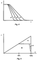
- Fig. 4 shows a diagram of the motor rotational speed n as a function of the time t dependant of the brake pedal depression.
- Fig 5 shows a diagram of the brake force F as a function of the brake pedal depression x.
- the industrial truck 1 shown in fig. 1 is preferably used indoors and includes as essential parts a chassis 2 to which a mast assembly 4 for the handling of goods is arranged.
- the truck is driven via an asynchronous motor 6 transferring power to a driving wheel 10 via a gearbox 8.
- the truck is further provided with support wheels 12 in the front end of the support arms 13.
- the support wheels 12 and the drive wheel 10 can be braked with electromagnetic brakes (not shown in fig 1).
- the truck is maneuvered in the usual way with among other things an accelerator 14 and a break pedal 16 whose starting position is defined as fully released position. Further there is a travel direction switch 18 and a steering wheel 20.
- the components for goods handling are maneuvered in some known manner that does not influence the invention and are therefor not described here.
- the driver gives signals to the truck regarding desired travel speed in the usual way by means of the accelerator 14.
- a signal is delivered to an electronic control unit 24 that in turn delivers a signal to a motor control unit 28 that control the motor 6.
- the signal that is transmitted to the electronic control unit varies dependent on how far the accelerator 14 is depressed and the electronic control unit 24 then delivers a signal to the motor control unit 28 to run the motor with a rotational speed corresponding to the accelerator position.
- the electronic control unit 24 delivering a signal of desired rotational speed to a rotational speed controller 38 in the electronic control unit delivering a signal to a torque controller 40 that via a power controller 42 delivers a current to the motor 6 with an amperage corresponding to suitable torque for the desired rotational speed.
- the signals are controlled in usual manner by means of feedback 44, 46 of actual values to the rotational speed controller 38 and the torque controller 40.
- the driver can brake the truck in three different ways by means of different maneuvering means; with the brake pedal 16, by changing travel direction by means of the travel direction switch 20, or by releasing the accelerator and letting the truck motor brake.
- the method for maneuvering with the brake pedal is now described below.
- a signal is delivered to the motor 6 via the electronic control unit 24 and the motor control unit 28 to reduce the rotational speed of the motor according to a characteristic with a predetermined deceleration.
- the deceleration characteristic is preferably constituted of the rotational speed as a function of the time.
- the controlling is done in a way that corresponds to the above method at accelerating.
- the signal transmitted to the electronic control unit 24 varies dependent of how far the pedal 16 is depressed with more depression giving a steeper characteristic, which thus gives a greater deceleration and thus a more powerful braking. This is apparent from fig 4 where the characteristics a-d show different decelerations dependant of how far the pedal is depressed, where characteristic d shows the greatest deceleration, that is the most powerful braking.
- the driving wheel 10 is connected to the motor 6 via a fixed gear 8 its rotational speed is directly proportional to the motor rotational speed and its brake distance is therefor the same independent of load since the control system will provide the motor with the braking torque that is required.
- Regeneration of brake energy to the battery 32 of the truck can be achieved in some known manner.
- a supplementary brake system When the brake pedal is depressed past a first predetermined position, for instance 50% of maximum depression, a supplementary brake system is activated. I n this case it is an electromagnetic brake 36 working on the support wheels 12 when an incoming signal is received from the electronic control unit 24.
- This brake 36 is analogous so that the braking torque increase with increased pedal depression past the mentioned position.
- the electronic control unit however continue to deliver a signal to the motor control unit 28 to follow the default characteristic a-d, possibly a steeper characteristic is chosen since the pedal depression increases. This results in the rotational speed of the motor following the characteristic according to fig 4 and the deceleration and wheel speed follow this independent of the activation of the support wheel brake.
- the resulting difference is that the motor control unit 28 will adjust to give the motor 6 the braking torque (motor brake) that is required in addition to the torque from the support wheel brake 36.
- the braking force F as a function of the brake pedal depression x.
- a final digital one step brake 30 is activated just before the pedal 16 reaches its bottom position. This brake subjects the driving wheel to a predetermined braking torque. Owing to this the motor brake only have to contribute with the torque that is required in addition to the torques of the one step brake 30 and the support wheel brake 36.
- the one step brake is preferably constituted of the same electromagnetic brake that is used as parking brake and its brake contribution is in fig 5 denoted with P.
- the truck braked according to a predetermined deceleration dependent of the degree of pedal depression but where the electronic control system activates supplementary brake devices in differing degree depending on type of operation so that the predetermined deceleration progress is followed independent of type of operation.
- the support wheel brake and parking brake are activated first after a predetermined pedal movement so that the motor brake can contribute with as big a part as possible and without the driver actually having to observe that different brake systems are activated. An even and secure brake progress is obtained.
- the brake progress can in the normal way be disrupted before the truck has stopped entirely by the driver releasing the pedal to its initial position.
- the inclinations of the characteristics a-d can be set differently depending on type of truck or actual driving conditions. This is preferably achieved by adjustment of a parameter that influence the electronic control unit 24, the parameter can preferably be changed by a service engineer.
- Braking by means of the travel directions switch 18 is done in principally the same way when the driver signals changed travel direction the motor is braked in the same way by the electronic control unit delivering signals concerning desired deceleration. Also here a number of deceleration characteristics a-d corresponding to fig 4 can exist. These are chosen depending the position of the accelerator 14 where a more depressed pedal gives a more powerful deceleration. Adjustment of the parameter 22 is possible here also. At this type of braking however the supplementary brakes 36, 30 are never activated.
- the same principal method is also used at so called auto braking where the truck is braked when the driver ease up the accelerator.
- the parameter 22 can be changed in order to enable different choice of characteristics corresponding to fig 4.
- the maneuvering means is constituted by the accelerator 14 that activates the braking at release towards inactivated position.
- the invention can within the scope of the Patent claims be executed according to other embodiments than those above described. It may for instance be used on other types of trucks where analogous conditions and problems exist. Furthermore the asynchronous motor can be replaced by some other type of electric motor used at trucks. Furthermore the brake pedal can be replaced by some other maneuvering means, as travel direction switch or accelerator according to the second and third brake method above, or some other type of known maneuvering means even if the mentioned ones are to be preferred since they are well tested and safe designs.
- the predetermined deceleration characteristics have the rotation speed of the motor as a function of time, which is suitable choice. It may also be possible to control according to other parameters that give a deceleration controlled braking, as vehicle speed or distance.
Landscapes
- Engineering & Computer Science (AREA)
- Power Engineering (AREA)
- Transportation (AREA)
- Mechanical Engineering (AREA)
- Life Sciences & Earth Sciences (AREA)
- Sustainable Development (AREA)
- Sustainable Energy (AREA)
- Physics & Mathematics (AREA)
- Electromagnetism (AREA)
- Electric Propulsion And Braking For Vehicles (AREA)
- Forklifts And Lifting Vehicles (AREA)
- Regulating Braking Force (AREA)
Applications Claiming Priority (2)
| Application Number | Priority Date | Filing Date | Title |
|---|---|---|---|
| SE9703652 | 1997-10-07 | ||
| SE9703652A SE520894C2 (sv) | 1997-10-07 | 1997-10-07 | Förfarande för att bromsa ett elmotordrivet fordon |
Publications (3)
| Publication Number | Publication Date |
|---|---|
| EP0908348A2 true EP0908348A2 (de) | 1999-04-14 |
| EP0908348A3 EP0908348A3 (de) | 2001-08-22 |
| EP0908348B1 EP0908348B1 (de) | 2009-12-09 |
Family
ID=20408533
Family Applications (1)
| Application Number | Title | Priority Date | Filing Date |
|---|---|---|---|
| EP98850151A Revoked EP0908348B1 (de) | 1997-10-07 | 1998-10-05 | Verfahren zum Bremsen eines elektrisch angetriebenen Fahrzeuges |
Country Status (4)
| Country | Link |
|---|---|
| US (1) | US6505715B1 (de) |
| EP (1) | EP0908348B1 (de) |
| DE (1) | DE69841354D1 (de) |
| SE (1) | SE520894C2 (de) |
Cited By (7)
| Publication number | Priority date | Publication date | Assignee | Title |
|---|---|---|---|---|
| FR2801011A1 (fr) * | 1999-11-16 | 2001-05-18 | Nippon Yusoki Co Ltd | Appareil de commande de chariot elevateur a fourche |
| FR2801847A1 (fr) * | 1999-11-16 | 2001-06-08 | Nippon Yusoki Co Ltd | Appareil de commande de chariot elevateur |
| FR2828860A1 (fr) * | 2001-08-21 | 2003-02-28 | Nippon Yusoki Co Ltd | Chariot elevateur |
| WO2004058552A1 (de) * | 2002-12-20 | 2004-07-15 | Zf Friedrichshafen Ag | Bremssystem und verfahren zum betrieb eines bremmsystems für elektrisch angetriebene fahrzeuge |
| DE10315297A1 (de) * | 2003-04-04 | 2004-10-28 | Jungheinrich Ag | Bremssystem für ein batteriebetriebenes Flurförderzeug |
| US8275523B2 (en) | 2007-12-12 | 2012-09-25 | Liebherr-Werk Nenzing Gmbh | Commercial vehicle with control means and method for controlling commercial vehicle |
| EP1712401A3 (de) * | 2005-04-12 | 2013-09-18 | OM Carrelli Elevatori S.p.A. | Flurförderzeug |
Families Citing this family (11)
| Publication number | Priority date | Publication date | Assignee | Title |
|---|---|---|---|---|
| US7500687B2 (en) * | 2004-01-31 | 2009-03-10 | Lockheed Martin Corporation | Vehicle suspension systems |
| US11219511B2 (en) | 2005-10-24 | 2022-01-11 | Biomet 3I, Llc | Methods for placing an implant analog in a physical model of the patient's mouth |
| US7393065B2 (en) * | 2006-06-01 | 2008-07-01 | Lockheed Martin Corporation | Redundant braking system |
| US20080066613A1 (en) * | 2006-09-15 | 2008-03-20 | Lockheed Martin Corporation | Perforated hull for vehicle blast shield |
| US20080173167A1 (en) | 2006-09-15 | 2008-07-24 | Armor Holdings | Vehicular based mine blast energy mitigation structure |
| CN101200170B (zh) * | 2006-12-11 | 2010-06-16 | 比亚迪股份有限公司 | 电动汽车油门加速装置及方法 |
| DE102008011719A1 (de) * | 2008-02-28 | 2009-09-03 | Jungheinrich Aktiengesellschaft | Bremssystem für ein Flurförderzeug |
| AU2012255865B8 (en) | 2011-05-16 | 2015-06-04 | Biomet 3I, Llc | Temporary abutment with combination of scanning features and provisionalization features |
| DE102014114427A1 (de) | 2014-10-06 | 2016-04-07 | Jungheinrich Aktiengesellschaft | Fahrzeug mit einer Fahrsteuerung |
| JP6934139B2 (ja) * | 2017-06-30 | 2021-09-15 | 三菱ロジスネクスト株式会社 | 電動走行制御装置および電動フォークリフト |
| DE102020122836A1 (de) | 2020-09-01 | 2022-03-03 | Jungheinrich Aktiengesellschaft | Flurförderzeug |
Family Cites Families (19)
| Publication number | Priority date | Publication date | Assignee | Title |
|---|---|---|---|---|
| US3845991A (en) * | 1973-08-31 | 1974-11-05 | Gen Signal Corp | Brake system for a light rail vehicle |
| US4240015A (en) * | 1977-08-15 | 1980-12-16 | Exxon Research & Engineering Co. | Control system and method for operating a DC motor |
| DE3027746A1 (de) * | 1980-07-22 | 1982-02-18 | Alfred Teves Gmbh, 6000 Frankfurt | Regelsystem fuer eine fahrzeugbremsanlage mit parallel wirkenden stroemungs- und reibungsbremse |
| US4398618A (en) * | 1981-02-27 | 1983-08-16 | Clark Equipment Company | Controller for electric traction motor |
| DE3137207A1 (de) | 1981-09-18 | 1983-04-07 | Dr.Ing.H.C. F. Porsche Ag, 7000 Stuttgart | "bremssystem, vorzugsweise fuer ein kraftfahrzeug" |
| US4468599A (en) * | 1981-12-23 | 1984-08-28 | General Electric Company | Plug current regulator |
| JP2611195B2 (ja) * | 1985-12-05 | 1997-05-21 | 日産自動車株式会社 | 車両用交流モータの制御装置 |
| JP2590825B2 (ja) * | 1986-07-12 | 1997-03-12 | トヨタ自動車株式会社 | マニユアル・電気二系統ブレーキ装置 |
| US4804893A (en) * | 1987-05-11 | 1989-02-14 | Caterpillar Industrial Inc. | Electric braking control |
| US5086865A (en) * | 1988-10-26 | 1992-02-11 | Isuzu Motors Limited | Regenerative braking system for car |
| JP3202032B2 (ja) * | 1991-06-03 | 2001-08-27 | 本田技研工業株式会社 | 電気自動車用ブレーキ制御装置 |
| US5340202A (en) * | 1991-10-30 | 1994-08-23 | Raymond Corporation | Service braking technique for material handling vehicles |
| US5378053A (en) * | 1993-12-07 | 1995-01-03 | Alliedsignal Inc. | Maximized regenerative braking vehicle braking controller |
| IT1269440B (it) * | 1994-01-19 | 1997-04-01 | Fita Om Carrelli Elevatori S P | Carrello elevatore a motorizzazione elettrica |
| JPH0885431A (ja) * | 1994-09-20 | 1996-04-02 | Sumitomo Electric Ind Ltd | 車両の制動力制御装置 |
| US5565751A (en) * | 1994-09-28 | 1996-10-15 | Trinity Industries, Inc. | Enhanced traction system for trolleybuses, powered from a 600-volt direct current power line |
| DE4440291C1 (de) * | 1994-11-11 | 1995-12-21 | Telefunken Microelectron | Verfahren zur Steuerung des Bremsprozesses bei einem Kraftfahrzeug |
| JP3089958B2 (ja) * | 1994-12-06 | 2000-09-18 | 三菱自動車工業株式会社 | 電気自動車の制動制御装置 |
| JPH0937407A (ja) * | 1995-07-18 | 1997-02-07 | Toyota Motor Corp | 回生制動制御装置 |
-
1997
- 1997-10-07 SE SE9703652A patent/SE520894C2/sv unknown
-
1998
- 1998-10-05 EP EP98850151A patent/EP0908348B1/de not_active Revoked
- 1998-10-05 DE DE69841354T patent/DE69841354D1/de not_active Expired - Lifetime
- 1998-10-07 US US09/168,032 patent/US6505715B1/en not_active Expired - Lifetime
Cited By (9)
| Publication number | Priority date | Publication date | Assignee | Title |
|---|---|---|---|---|
| FR2801011A1 (fr) * | 1999-11-16 | 2001-05-18 | Nippon Yusoki Co Ltd | Appareil de commande de chariot elevateur a fourche |
| FR2801847A1 (fr) * | 1999-11-16 | 2001-06-08 | Nippon Yusoki Co Ltd | Appareil de commande de chariot elevateur |
| FR2828860A1 (fr) * | 2001-08-21 | 2003-02-28 | Nippon Yusoki Co Ltd | Chariot elevateur |
| US7165819B2 (en) | 2001-08-21 | 2007-01-23 | Nippon Yusoki Co., Ltd. | Lift truck |
| WO2004058552A1 (de) * | 2002-12-20 | 2004-07-15 | Zf Friedrichshafen Ag | Bremssystem und verfahren zum betrieb eines bremmsystems für elektrisch angetriebene fahrzeuge |
| DE10315297A1 (de) * | 2003-04-04 | 2004-10-28 | Jungheinrich Ag | Bremssystem für ein batteriebetriebenes Flurförderzeug |
| US7275794B2 (en) | 2003-04-04 | 2007-10-02 | Jungheinrich Aktiengesellschaft | Braking system for a battery powered industrial truck |
| EP1712401A3 (de) * | 2005-04-12 | 2013-09-18 | OM Carrelli Elevatori S.p.A. | Flurförderzeug |
| US8275523B2 (en) | 2007-12-12 | 2012-09-25 | Liebherr-Werk Nenzing Gmbh | Commercial vehicle with control means and method for controlling commercial vehicle |
Also Published As
| Publication number | Publication date |
|---|---|
| SE9703652L (sv) | 1999-04-08 |
| US6505715B1 (en) | 2003-01-14 |
| EP0908348B1 (de) | 2009-12-09 |
| SE520894C2 (sv) | 2003-09-09 |
| SE9703652D0 (sv) | 1997-10-07 |
| EP0908348A3 (de) | 2001-08-22 |
| US20010003401A1 (en) | 2001-06-14 |
| DE69841354D1 (de) | 2010-01-21 |
Similar Documents
| Publication | Publication Date | Title |
|---|---|---|
| EP0908348B1 (de) | Verfahren zum Bremsen eines elektrisch angetriebenen Fahrzeuges | |
| US6081081A (en) | Electric motor-driven wheel brake for vehicles | |
| JP7212233B2 (ja) | 車両を制御するためのシステムおよび方法 | |
| JP5836272B2 (ja) | 電気駆動式機械の駆動方向を制御するための方法とシステム | |
| US5476310A (en) | Braking apparatus for electric vehicle | |
| US8548707B2 (en) | Braking system and method for braking a vehicle having a hybrid drive | |
| RU2617760C2 (ru) | Способ эксплуатации механической стояночной тормозной системы | |
| JP2019536403A5 (de) | ||
| EP2462013A1 (de) | Verfahren zur regelung eines radbremsschlupfes und radbremsschlupfregelsystem für ein fahrzeug mit einem elektroantrieb | |
| US6361469B1 (en) | Parking lock for a vehicle having an electrical drive, and an electrical drive for a vehicle | |
| RU2243429C2 (ru) | Система электронной стабилизации автомобиля (варианты) и способ управления крутящим моментом (варианты) | |
| GB2431444A (en) | Brake control system | |
| JP2004026146A (ja) | 車両の制動方法及び装置 | |
| EP1866193B1 (de) | Bremssystem für einen hubstapler | |
| CN107521476B (zh) | 动力传动系统制动和摩擦制动车辆的方法和总成 | |
| US6485111B2 (en) | Power assisted braking system | |
| US20250178454A1 (en) | Longitudinal Deceleration During a Creeping Operation for Motor Vehicles With Two Electrically Drivable Axles | |
| CN112823109A (zh) | 用于在紧急制动时减速机动车的方法和机动车 | |
| CN1535860B (zh) | 电动工业用货车的制动系统 | |
| JP2020504048A (ja) | 自動車を作動させるための方法および装置並びに自動車 | |
| US20060225972A1 (en) | Device and method for operating a motor-vehicle parking brake | |
| WO2023274836A1 (de) | Verfahren zum betreiben eines elektrifizierten antriebsstrangs für eine arbeitsmaschine, elektrifizierter antriebsstrang für eine arbeitsmaschine und arbeitsmaschine | |
| NL1010852C1 (nl) | Aanhangwagen-beremming. | |
| KR100372433B1 (ko) | 자동차의 주차브레이크 | |
| KR200165826Y1 (ko) | 오르막길 보조 제동장치 |
Legal Events
| Date | Code | Title | Description |
|---|---|---|---|
| PUAI | Public reference made under article 153(3) epc to a published international application that has entered the european phase |
Free format text: ORIGINAL CODE: 0009012 |
|
| AK | Designated contracting states |
Kind code of ref document: A2 Designated state(s): AT BE CH CY DE DK ES FI FR GB GR IE IT LI LU MC NL PT SE |
|
| AX | Request for extension of the european patent |
Free format text: AL;LT;LV;MK;RO;SI |
|
| PUAL | Search report despatched |
Free format text: ORIGINAL CODE: 0009013 |
|
| AK | Designated contracting states |
Kind code of ref document: A3 Designated state(s): AT BE CH CY DE DK ES FI FR GB GR IE IT LI LU MC NL PT SE |
|
| AX | Request for extension of the european patent |
Free format text: AL;LT;LV;MK;RO;SI |
|
| RIC1 | Information provided on ipc code assigned before grant |
Free format text: 7B 60L 15/20 A, 7B 60L 7/26 B, 7B 60L 11/18 B |
|
| 17P | Request for examination filed |
Effective date: 20020222 |
|
| AKX | Designation fees paid |
Free format text: BE DE FR GB IT NL SE |
|
| 17Q | First examination report despatched |
Effective date: 20071001 |
|
| RAP1 | Party data changed (applicant data changed or rights of an application transferred) |
Owner name: TOYOTA INDUSTRIES SWEDEN AB |
|
| GRAP | Despatch of communication of intention to grant a patent |
Free format text: ORIGINAL CODE: EPIDOSNIGR1 |
|
| GRAS | Grant fee paid |
Free format text: ORIGINAL CODE: EPIDOSNIGR3 |
|
| GRAA | (expected) grant |
Free format text: ORIGINAL CODE: 0009210 |
|
| AK | Designated contracting states |
Kind code of ref document: B1 Designated state(s): BE DE FR GB IT NL SE |
|
| REG | Reference to a national code |
Ref country code: GB Ref legal event code: FG4D |
|
| REF | Corresponds to: |
Ref document number: 69841354 Country of ref document: DE Date of ref document: 20100121 Kind code of ref document: P |
|
| REG | Reference to a national code |
Ref country code: NL Ref legal event code: VDEP Effective date: 20091209 |
|
| PG25 | Lapsed in a contracting state [announced via postgrant information from national office to epo] |
Ref country code: SE Free format text: LAPSE BECAUSE OF FAILURE TO SUBMIT A TRANSLATION OF THE DESCRIPTION OR TO PAY THE FEE WITHIN THE PRESCRIBED TIME-LIMIT Effective date: 20091209 |
|
| RAP2 | Party data changed (patent owner data changed or rights of a patent transferred) |
Owner name: TOYOTA MATERIAL HANDLING EUROPE AB |
|
| PG25 | Lapsed in a contracting state [announced via postgrant information from national office to epo] |
Ref country code: NL Free format text: LAPSE BECAUSE OF FAILURE TO SUBMIT A TRANSLATION OF THE DESCRIPTION OR TO PAY THE FEE WITHIN THE PRESCRIBED TIME-LIMIT Effective date: 20091209 |
|
| PG25 | Lapsed in a contracting state [announced via postgrant information from national office to epo] |
Ref country code: BE Free format text: LAPSE BECAUSE OF FAILURE TO SUBMIT A TRANSLATION OF THE DESCRIPTION OR TO PAY THE FEE WITHIN THE PRESCRIBED TIME-LIMIT Effective date: 20091209 |
|
| PLBI | Opposition filed |
Free format text: ORIGINAL CODE: 0009260 |
|
| PLAX | Notice of opposition and request to file observation + time limit sent |
Free format text: ORIGINAL CODE: EPIDOSNOBS2 |
|
| 26 | Opposition filed |
Opponent name: STILL GMBH Effective date: 20100909 |
|
| PLAF | Information modified related to communication of a notice of opposition and request to file observations + time limit |
Free format text: ORIGINAL CODE: EPIDOSCOBS2 |
|
| PLBB | Reply of patent proprietor to notice(s) of opposition received |
Free format text: ORIGINAL CODE: EPIDOSNOBS3 |
|
| REG | Reference to a national code |
Ref country code: FR Ref legal event code: ST Effective date: 20140630 |
|
| PG25 | Lapsed in a contracting state [announced via postgrant information from national office to epo] |
Ref country code: FR Free format text: LAPSE BECAUSE OF NON-PAYMENT OF DUE FEES Effective date: 20131031 |
|
| REG | Reference to a national code |
Ref country code: FR Ref legal event code: D3 Effective date: 20141230 |
|
| PGRI | Patent reinstated in contracting state [announced from national office to epo] |
Ref country code: FR Effective date: 20141230 |
|
| REG | Reference to a national code |
Ref country code: FR Ref legal event code: PLFP Year of fee payment: 18 |
|
| PGFP | Annual fee paid to national office [announced via postgrant information from national office to epo] |
Ref country code: DE Payment date: 20151026 Year of fee payment: 18 Ref country code: GB Payment date: 20151027 Year of fee payment: 18 Ref country code: IT Payment date: 20151019 Year of fee payment: 18 |
|
| REG | Reference to a national code |
Ref country code: DE Ref legal event code: R103 Ref document number: 69841354 Country of ref document: DE Ref country code: DE Ref legal event code: R064 Ref document number: 69841354 Country of ref document: DE |
|
| PGFP | Annual fee paid to national office [announced via postgrant information from national office to epo] |
Ref country code: FR Payment date: 20151102 Year of fee payment: 18 |
|
| RDAF | Communication despatched that patent is revoked |
Free format text: ORIGINAL CODE: EPIDOSNREV1 |
|
| RDAG | Patent revoked |
Free format text: ORIGINAL CODE: 0009271 |
|
| STAA | Information on the status of an ep patent application or granted ep patent |
Free format text: STATUS: PATENT REVOKED |
|
| 27W | Patent revoked |
Effective date: 20160204 |
|
| GBPR | Gb: patent revoked under art. 102 of the ep convention designating the uk as contracting state |
Effective date: 20160204 |