EP0908351A2 - Haltevorrichtung für Grossraumfahrzeuge, wie Omnibusse - Google Patents
Haltevorrichtung für Grossraumfahrzeuge, wie Omnibusse Download PDFInfo
- Publication number
- EP0908351A2 EP0908351A2 EP98112697A EP98112697A EP0908351A2 EP 0908351 A2 EP0908351 A2 EP 0908351A2 EP 98112697 A EP98112697 A EP 98112697A EP 98112697 A EP98112697 A EP 98112697A EP 0908351 A2 EP0908351 A2 EP 0908351A2
- Authority
- EP
- European Patent Office
- Prior art keywords
- holding device
- socket
- parting line
- handle body
- bushing
- Prior art date
- Legal status (The legal status is an assumption and is not a legal conclusion. Google has not performed a legal analysis and makes no representation as to the accuracy of the status listed.)
- Granted
Links
Images

Classifications
-
- B—PERFORMING OPERATIONS; TRANSPORTING
- B60—VEHICLES IN GENERAL
- B60N—SEATS SPECIALLY ADAPTED FOR VEHICLES; VEHICLE PASSENGER ACCOMMODATION NOT OTHERWISE PROVIDED FOR
- B60N3/00—Arrangements or adaptations of other passenger fittings, not otherwise provided for
- B60N3/02—Arrangements or adaptations of other passenger fittings, not otherwise provided for of hand grips or straps
Definitions
- the invention relates to a holding device for large vehicles, like buses, with one concentrically encompassing a handrail Socket and a handle body arranged thereon.
- a holding device of the generic type is known from DE 34 13 183 A1 became known.
- the known holding device consists of a loop-shaped handle body and an associated in itself closed socket, which concentrically encompasses a handrail.
- the assembly the known holding device can only take place if the holding rod not yet with other poles to a handrail system in one Large vehicle was put together. But it is more important that the known holding device is not easily removable, but disassembly of the entire handrail system required.
- vandalism has occurred in recent years made broad, which also does not prevent damage to holding devices of the kind in question shrinks. So it’s very common that in large public transport vehicles, such as buses, Rail vehicles but also cable car cabins due to damage Holders that have become unusable must be replaced. Such a Replacing damaged brackets is extremely time consuming, though Holding devices according to DE 34 13 183 A1 are to be used.
- the holding device according to the invention can be done in the simplest way Widen the socket radially on a support rod, where the parting line, which is then wide open, forms a kind of clamp mouth.
- the material used for the holding device has a certain elasticity with resilience, so that the bushing strives to resume their closed socket shape as soon as the handrail the parting line has passed. Just as easy as the assembly Disassembly by widening the socket and pulling off the holding device from the handrail.
- the material lobes arranged on the socket give the holding device a good appearance and allow in simple arrangement of the handle body, which is a contraction the socket and thus a clamping of the socket on the support rod, as soon as a person holds on to the handle body and this automatically loaded with a pulling force.
- the measure according to claim 2 causes the holding device largely against unwanted slipping on the support rod in the axial Direction is secured in addition to the clamping effect.
- a particularly simple and inexpensive manufacture of the holding device is achieved by the measures according to claim 3.
- the socket increased torsional rigidity and improved adaptability different handrail diameters, which vary between 28 and 35 mm can. In particular, it also ensures that the parting line cannot open beyond a certain degree unintentionally.
- the measure according to claim 5 gives the holding device an increased Stability and a particularly good appearance.
- the material rag and material formations together form a housing in which the fasteners for the handle body and the socket-side end of the handle body arrange largely concealed.
- the arrangement of mounting holes in the material tab can already be accomplish in the manufacture of the socket body, so that the attachment the handle body can be done by simply inserting bolts, only a non-positive holder is required for the bolts.
- the handle body can according to claim 6 from a simple hand strap consist of a textile tape or belt material can.
- a hand strap is placed around two spaced bolts with a tensile force exerted on them, make sure that the bolts according to the Resulting forces are pulled against each other with a resulting one Clamping force of the socket on the handrail.
- the handle body can also be made of a dimensionally stable material be formed, but it is recommended in the connection area to Provide a socket made of tape or belt material for the socket body.
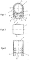
- the new holding device consists of a socket 1 and an associated Handle body 2, in Fig. 1 as a dash-dotted hand strap is indicated.
- Fig. 1 As a dash-dotted hand strap is indicated.
- the socket 1 In its use position, which can be seen in particular in FIG. 1 the socket 1 is closed and concentrically encompasses one Handrail 3, as usually in large vehicles, the vehicle roof neighboring, is to be found.
- the handrail is with several Holding devices of the type in question are equipped.
- the socket 1 is interrupted by an axially continuous parting line 4 and elastically expandable.
- the socket 1 consists of a plastic injection molded part and Fig. 4 and 5 show the possible manufacturing situation in Tool of an injection mold.
- the parting line 4 each adjacent material flaps 5 and 6 arranged on the left and right or molded.
- the material tabs 5 and 6 are perpendicular to the bush axis. In the expanded state of the socket 1, the material tabs 5 and 6 spaced apart while they are in the position of use of the socket 1 overlap, as is clearly shown in Fig. 1.
- the shorter material tabs 5 each have a guide groove 8 and longer material tab 6 each have a guide cam received therein 9 on.
- the material tabs 5 are just like the material tabs 6 by material projections 10 arranged tangentially on the bushing 1 with one another connected to a U-shape.
- the two material lobes 5 have the same as the two material lobes 6 in each case aligned mounting holes 11 to perform and anchoring fastening bolts 12 are provided.
- This parallel to Fastening bolts 12 aligned with the socket axis are of a Loop 13 of the handle body 2 spans with the result that with a tensile load of the handle body 2 in the arrow direction F, the fastening bolts 12 are moved towards one another and the socket 1 clamps the support rod 3.
- Around counteracting slipping of the bushing 1 on the holding rod 3 To increase the clamping effect are inside the socket 1 on the handrail 3 supporting ribs 14 are formed, preferably from one opposite the other socket body softer material with non-slip Properties exist.
Landscapes
- Engineering & Computer Science (AREA)
- Transportation (AREA)
- Mechanical Engineering (AREA)
- Passenger Equipment (AREA)
- Clamps And Clips (AREA)
- Mutual Connection Of Rods And Tubes (AREA)
- Connection Of Plates (AREA)
- Arrangement Or Mounting Of Propulsion Units For Vehicles (AREA)
- Body Structure For Vehicles (AREA)
- Vehicle Step Arrangements And Article Storage (AREA)
Abstract
Description
- Fig. 1
- die Haltevorrichtung in einer Stirnansicht,
- Fig. 2
- eine Draufsicht nach Fig. 1,
- Fig. 3
- eine Seitenansicht nach Fig. 1,
- Fig. 4
- die Buchse der Haltevorrichtung in leicht gespreizter Offenstellung und
- Fig. 5
- die Buchse nach Fig. 4 in einer Schnittdarstellung.
Claims (7)
- Haltevorrichtung für Großraumfahrzeuge, wie Omnibusse, mit einer eine Haltestange (3) konzentrisch umgreifenden Buchse (1) und einem daran angeordneten Griffkörper (2), dadurch gekennzeichnet, daß die Buchse (1) durch eine axial durchlaufende Trennfuge (4) elastisch aufweitbar ausgebildet ist, daß an den Enden der Buchse (1) jeweils zwei, der Trennfuge (4) jeweils links und rechts benachbarte Materiallappen (5, 6) radial überstehend angeordnet sind, daß die Materiallappen (5, 6) bei aufgeweiteter Buchse (1) einander beabstandet sind und sich bei weitgehend geschlossener Trennfuge (4) einander überlappen und daß an den Materiallappen (4, 5) der Griffkörper (2) so angeordnet ist, daß sich bei einer auf ihn einwirkenden Zugkraft eine Verengung der Trennfuge (4) und damit eine Klemmung der Buchse (1) an der Haltestange (3) einstellt.
- Haltevorrichtung nach Anspruch 1, dadurch gekennzeichnet, daß im Innern der Buchse (1) sich an der Haltestange (3) abstützende Rippen (14), Noppen oder dgl. angeordnet sind, die aus einem gegenüber dem sonstigen Buchsenkörper weicherem Material mit rutschhemmenden Eigenschaften bestehen.
- Haltevorrichtung nach Anspruch 1, dadurch gekennzeichnet, daß die Buchse (1) als einstückiges Kunststoff-Spritzgußteil ausgebildet ist.
- Haltevorrichtung nach wenigstens einem der vorangegangenen Ansprüche, dadurch gekennzeichnet, daß zwischen jedem Paar der an den Buchsenenden angeformten Materiallappen (5 bzw. 6) eine Führungseinrichtung vorgesehen ist mit einer beidendig geschlossenen Führungsnut (8) an dem einen Materiallappen (5) und einem darin eingreifenden Nocken (9) an dem anderen Materiallappen (6).
- Haltevorrichtung nach wenigstens einem der vorangegangenen Ansprüche, dadurch gekennzeichnet, daß die Buchse (1) tangentiale, die Materiallappen (5, 6) links der Trennfuge (4) und die Materiallappen (5, 6) rechts der Trennfuge (4) jeweils zu einer U-Form miteinander verbindende Materialanformungen (10) aufweist.
- Haltevorrichtung nach wenigstens einem der vorangegangenen Ansprüche, dadurch gekennzeichnet, daß die Materiallappen (5, 6) miteinander fluchtende Montagelöcher (11) zur Aufnahme von sich parallel zur Buchsenachse erstreckende Befestigungsbolzen (12) für den Griffkörper (2) aufweisen.
- Haltevorrichtung nach wenigstens einem der vorangegangenen Ansprüche, dadurch gekennzeichnet, daß der Griffkörper (2) aus einer Handschlaufe besteht.
Applications Claiming Priority (2)
| Application Number | Priority Date | Filing Date | Title |
|---|---|---|---|
| DE19745117 | 1997-10-11 | ||
| DE19745117A DE19745117A1 (de) | 1997-10-11 | 1997-10-11 | Haltevorrichtung für Großraumfahrzeuge, wie Omnibusse |
Publications (3)
| Publication Number | Publication Date |
|---|---|
| EP0908351A2 true EP0908351A2 (de) | 1999-04-14 |
| EP0908351A3 EP0908351A3 (de) | 1999-08-18 |
| EP0908351B1 EP0908351B1 (de) | 2001-10-31 |
Family
ID=7845355
Family Applications (1)
| Application Number | Title | Priority Date | Filing Date |
|---|---|---|---|
| EP98112697A Expired - Lifetime EP0908351B1 (de) | 1997-10-11 | 1998-07-09 | Haltevorrichtung für Grossraumfahrzeuge, wie Omnibusse |
Country Status (9)
| Country | Link |
|---|---|
| EP (1) | EP0908351B1 (de) |
| CZ (1) | CZ294061B6 (de) |
| DE (2) | DE19745117A1 (de) |
| ES (1) | ES2167042T3 (de) |
| HU (1) | HU218808B (de) |
| PT (1) | PT908351E (de) |
| SK (1) | SK283294B6 (de) |
| TR (1) | TR199802037A3 (de) |
| YU (1) | YU49168B (de) |
Families Citing this family (1)
| Publication number | Priority date | Publication date | Assignee | Title |
|---|---|---|---|---|
| DE102012000328A1 (de) * | 2012-01-11 | 2013-07-11 | Happich Gmbh | Befestigungselement |
Citations (1)
| Publication number | Priority date | Publication date | Assignee | Title |
|---|---|---|---|---|
| DE3413183A1 (de) | 1984-04-07 | 1985-10-17 | Gebr. Happich Gmbh, 5600 Wuppertal | Haltegriff, insbesondere fuer grossraumfahrzeuge |
Family Cites Families (5)
| Publication number | Priority date | Publication date | Assignee | Title |
|---|---|---|---|---|
| US2130283A (en) * | 1938-05-12 | 1938-09-13 | Electric Service Supplies Co | Handhold |
| GB1566712A (en) * | 1977-02-04 | 1980-05-08 | British Leyland Cars Ltd | Hand and guard rails |
| FR2401796A1 (fr) * | 1977-08-31 | 1979-03-30 | Rbe App | Poignee de maintien pour vehicules de transports en commun |
| CA2129801C (en) * | 1994-08-09 | 1998-12-22 | Chandler Aurora | Multiple hand grip system |
| GB9520000D0 (en) * | 1995-09-30 | 1995-12-06 | Gamwell Douglas F | Improvements in or relating to passenger supports |
-
1997
- 1997-10-11 DE DE19745117A patent/DE19745117A1/de not_active Withdrawn
-
1998
- 1998-07-09 ES ES98112697T patent/ES2167042T3/es not_active Expired - Lifetime
- 1998-07-09 PT PT98112697T patent/PT908351E/pt unknown
- 1998-07-09 EP EP98112697A patent/EP0908351B1/de not_active Expired - Lifetime
- 1998-07-09 DE DE59801936T patent/DE59801936D1/de not_active Expired - Fee Related
- 1998-08-17 CZ CZ19982596A patent/CZ294061B6/cs not_active IP Right Cessation
- 1998-08-31 SK SK1203-98A patent/SK283294B6/sk unknown
- 1998-09-02 YU YU38298A patent/YU49168B/sh unknown
- 1998-09-21 HU HU9802126A patent/HU218808B/hu not_active IP Right Cessation
- 1998-10-09 TR TR1998/02037A patent/TR199802037A3/tr unknown
Patent Citations (1)
| Publication number | Priority date | Publication date | Assignee | Title |
|---|---|---|---|---|
| DE3413183A1 (de) | 1984-04-07 | 1985-10-17 | Gebr. Happich Gmbh, 5600 Wuppertal | Haltegriff, insbesondere fuer grossraumfahrzeuge |
Also Published As
| Publication number | Publication date |
|---|---|
| SK283294B6 (sk) | 2003-05-02 |
| YU49168B (sh) | 2004-05-12 |
| HUP9802126A2 (hu) | 1999-05-28 |
| EP0908351A3 (de) | 1999-08-18 |
| TR199802037A2 (xx) | 1999-10-21 |
| HUP9802126A3 (en) | 2000-04-28 |
| TR199802037A3 (tr) | 1999-10-21 |
| DE59801936D1 (de) | 2001-12-06 |
| HU218808B (hu) | 2000-12-28 |
| CZ259698A3 (cs) | 1999-04-14 |
| EP0908351B1 (de) | 2001-10-31 |
| PT908351E (pt) | 2002-04-29 |
| HU9802126D0 (en) | 1998-11-30 |
| CZ294061B6 (cs) | 2004-09-15 |
| YU38298A (sh) | 2001-07-10 |
| DE19745117A1 (de) | 1999-04-15 |
| ES2167042T3 (es) | 2002-05-01 |
| SK120398A3 (en) | 1999-06-11 |
Similar Documents
| Publication | Publication Date | Title |
|---|---|---|
| DE19534437C2 (de) | Schelle zur Verbindung von zwei rohrförmigen Leitungsteilen | |
| DE4318167A1 (de) | Halterung für die variable Anbringung eines Fahrradschlosses an einem Rohrrahmen | |
| EP0758728A1 (de) | Halteelement aus Kunststoff | |
| DE4302408A1 (de) | Einteiliges Halteelement | |
| DE4332286C2 (de) | Stoßfänger-Befestigungsvorrichtung | |
| DE69705188T2 (de) | Toleranzausgleichclips | |
| DE69001764T2 (de) | Befestigungsvorrichtung. | |
| DE2608190A1 (de) | Netz- oder kettenartige, auf fahrzeugraeder montierbare gleitschutzvorrichtung | |
| DE9212843U1 (de) | Halter zur Befestigung eines Bügelschlosses an einem Zweirad | |
| EP0158742B1 (de) | Kabelwagen | |
| DE19808044C2 (de) | Anordnung zum losen Verbinden wenigstens zweier Bauelemente mittels Steckverbindung, beispielsweise zum Verbinden eines Dichtungsprofils mit einer Kraftfahrzeugkarossie | |
| DE19547070A1 (de) | Befestigungsvorrichtung mit einem Halteelement für eine Leitung | |
| EP0908351B1 (de) | Haltevorrichtung für Grossraumfahrzeuge, wie Omnibusse | |
| EP0905841A2 (de) | Schaltschrank zur Aufnahme elektrischer und elektronischer Aggregate | |
| EP0020943A1 (de) | Hängeklemme für isolierte Leiter und Leiterbündel | |
| DE3028998C2 (de) | Haltevorrichtung | |
| DE3607744C2 (de) | ||
| DE3423317C2 (de) | Wischvorrichtung für Scheiben von Kraftfahrzeugen | |
| EP0601350B1 (de) | Dachreling für Kraftfahrzeuge | |
| DE3539392C2 (de) | ||
| DE8306111U1 (de) | Kotflügel aus Kunststoff | |
| EP0809586A2 (de) | Haltevorrichtung | |
| DE69802596T2 (de) | Lösbare Befestigungsvorrichtung insbesondere für ein Karosseriebauteil | |
| EP0896186A1 (de) | Öffenbare Pendelschale | |
| DE3317020C1 (de) | Aus Kunststoff bestehendes, als länglicher Körper mit im wesentlichen rundem Querschnitt ausgebildetes Befestigungselement mit endseitigen Klipsverbindungen |
Legal Events
| Date | Code | Title | Description |
|---|---|---|---|
| PUAI | Public reference made under article 153(3) epc to a published international application that has entered the european phase |
Free format text: ORIGINAL CODE: 0009012 |
|
| AK | Designated contracting states |
Kind code of ref document: A2 Designated state(s): BE DE ES FI FR GB IT LU NL PT SE |
|
| AX | Request for extension of the european patent |
Free format text: AL;LT;LV;MK;RO;SI |
|
| PUAL | Search report despatched |
Free format text: ORIGINAL CODE: 0009013 |
|
| AK | Designated contracting states |
Kind code of ref document: A3 Designated state(s): AT BE CH CY DE DK ES FI FR GB GR IE IT LI LU MC NL PT SE |
|
| AX | Request for extension of the european patent |
Free format text: AL;LT;LV;MK;RO;SI |
|
| 17P | Request for examination filed |
Effective date: 19990720 |
|
| AKX | Designation fees paid |
Free format text: BE DE ES FI FR GB IT LU NL PT SE |
|
| GRAG | Despatch of communication of intention to grant |
Free format text: ORIGINAL CODE: EPIDOS AGRA |
|
| GRAG | Despatch of communication of intention to grant |
Free format text: ORIGINAL CODE: EPIDOS AGRA |
|
| GRAH | Despatch of communication of intention to grant a patent |
Free format text: ORIGINAL CODE: EPIDOS IGRA |
|
| 17Q | First examination report despatched |
Effective date: 20010706 |
|
| GRAG | Despatch of communication of intention to grant |
Free format text: ORIGINAL CODE: EPIDOS AGRA |
|
| GRAH | Despatch of communication of intention to grant a patent |
Free format text: ORIGINAL CODE: EPIDOS IGRA |
|
| GRAH | Despatch of communication of intention to grant a patent |
Free format text: ORIGINAL CODE: EPIDOS IGRA |
|
| GRAA | (expected) grant |
Free format text: ORIGINAL CODE: 0009210 |
|
| RIN1 | Information on inventor provided before grant (corrected) |
Inventor name: HANOLD, RICHARD Inventor name: NUYAN, VEDAT |
|
| AK | Designated contracting states |
Kind code of ref document: B1 Designated state(s): BE DE ES FI FR GB IT LU NL PT SE |
|
| REF | Corresponds to: |
Ref document number: 59801936 Country of ref document: DE Date of ref document: 20011206 |
|
| REG | Reference to a national code |
Ref country code: GB Ref legal event code: IF02 |
|
| GBT | Gb: translation of ep patent filed (gb section 77(6)(a)/1977) |
Effective date: 20020124 |
|
| ET | Fr: translation filed | ||
| REG | Reference to a national code |
Ref country code: PT Ref legal event code: SC4A Free format text: AVAILABILITY OF NATIONAL TRANSLATION Effective date: 20020122 |
|
| REG | Reference to a national code |
Ref country code: ES Ref legal event code: FG2A Ref document number: 2167042 Country of ref document: ES Kind code of ref document: T3 |
|
| PLBE | No opposition filed within time limit |
Free format text: ORIGINAL CODE: 0009261 |
|
| STAA | Information on the status of an ep patent application or granted ep patent |
Free format text: STATUS: NO OPPOSITION FILED WITHIN TIME LIMIT |
|
| 26N | No opposition filed | ||
| PGFP | Annual fee paid to national office [announced via postgrant information from national office to epo] |
Ref country code: FR Payment date: 20030609 Year of fee payment: 6 |
|
| PGFP | Annual fee paid to national office [announced via postgrant information from national office to epo] |
Ref country code: GB Payment date: 20030612 Year of fee payment: 6 Ref country code: FI Payment date: 20030612 Year of fee payment: 6 |
|
| PGFP | Annual fee paid to national office [announced via postgrant information from national office to epo] |
Ref country code: PT Payment date: 20030617 Year of fee payment: 6 |
|
| PGFP | Annual fee paid to national office [announced via postgrant information from national office to epo] |
Ref country code: NL Payment date: 20030619 Year of fee payment: 6 |
|
| PGFP | Annual fee paid to national office [announced via postgrant information from national office to epo] |
Ref country code: SE Payment date: 20030623 Year of fee payment: 6 |
|
| PGFP | Annual fee paid to national office [announced via postgrant information from national office to epo] |
Ref country code: DE Payment date: 20030626 Year of fee payment: 6 |
|
| PGFP | Annual fee paid to national office [announced via postgrant information from national office to epo] |
Ref country code: LU Payment date: 20030630 Year of fee payment: 6 |
|
| PGFP | Annual fee paid to national office [announced via postgrant information from national office to epo] |
Ref country code: ES Payment date: 20030707 Year of fee payment: 6 |
|
| PGFP | Annual fee paid to national office [announced via postgrant information from national office to epo] |
Ref country code: BE Payment date: 20030710 Year of fee payment: 6 |
|
| PG25 | Lapsed in a contracting state [announced via postgrant information from national office to epo] |
Ref country code: LU Free format text: LAPSE BECAUSE OF NON-PAYMENT OF DUE FEES Effective date: 20040709 Ref country code: GB Free format text: LAPSE BECAUSE OF NON-PAYMENT OF DUE FEES Effective date: 20040709 Ref country code: FI Free format text: LAPSE BECAUSE OF NON-PAYMENT OF DUE FEES Effective date: 20040709 |
|
| PG25 | Lapsed in a contracting state [announced via postgrant information from national office to epo] |
Ref country code: SE Free format text: LAPSE BECAUSE OF NON-PAYMENT OF DUE FEES Effective date: 20040710 Ref country code: ES Free format text: LAPSE BECAUSE OF NON-PAYMENT OF DUE FEES Effective date: 20040710 |
|
| PG25 | Lapsed in a contracting state [announced via postgrant information from national office to epo] |
Ref country code: BE Free format text: LAPSE BECAUSE OF NON-PAYMENT OF DUE FEES Effective date: 20040731 |
|
| PG25 | Lapsed in a contracting state [announced via postgrant information from national office to epo] |
Ref country code: PT Free format text: LAPSE BECAUSE OF NON-PAYMENT OF DUE FEES Effective date: 20050110 |
|
| BERE | Be: lapsed |
Owner name: *HAPPICH FAHRZEUG- UND INDUSTRIETEILE G.M.B.H. Effective date: 20040731 |
|
| PG25 | Lapsed in a contracting state [announced via postgrant information from national office to epo] |
Ref country code: NL Free format text: LAPSE BECAUSE OF NON-PAYMENT OF DUE FEES Effective date: 20050201 Ref country code: DE Free format text: LAPSE BECAUSE OF NON-PAYMENT OF DUE FEES Effective date: 20050201 |
|
| EUG | Se: european patent has lapsed | ||
| GBPC | Gb: european patent ceased through non-payment of renewal fee |
Effective date: 20040709 |
|
| PG25 | Lapsed in a contracting state [announced via postgrant information from national office to epo] |
Ref country code: FR Free format text: LAPSE BECAUSE OF NON-PAYMENT OF DUE FEES Effective date: 20050331 |
|
| REG | Reference to a national code |
Ref country code: PT Ref legal event code: MM4A Free format text: LAPSE DUE TO NON-PAYMENT OF FEES Effective date: 20050110 |
|
| NLV4 | Nl: lapsed or anulled due to non-payment of the annual fee |
Effective date: 20050201 |
|
| REG | Reference to a national code |
Ref country code: FR Ref legal event code: ST |
|
| PG25 | Lapsed in a contracting state [announced via postgrant information from national office to epo] |
Ref country code: IT Free format text: LAPSE BECAUSE OF NON-PAYMENT OF DUE FEES Effective date: 20050709 |
|
| REG | Reference to a national code |
Ref country code: ES Ref legal event code: FD2A Effective date: 20040710 |
|
| BERE | Be: lapsed |
Owner name: *HAPPICH FAHRZEUG- UND INDUSTRIETEILE G.M.B.H. Effective date: 20040731 |