EP0908358A2 - Dispositifs de ceinture d'air - Google Patents
Dispositifs de ceinture d'air Download PDFInfo
- Publication number
- EP0908358A2 EP0908358A2 EP98116550A EP98116550A EP0908358A2 EP 0908358 A2 EP0908358 A2 EP 0908358A2 EP 98116550 A EP98116550 A EP 98116550A EP 98116550 A EP98116550 A EP 98116550A EP 0908358 A2 EP0908358 A2 EP 0908358A2
- Authority
- EP
- European Patent Office
- Prior art keywords
- gas
- buckle
- tongue
- plug
- air belt
- Prior art date
- Legal status (The legal status is an assumption and is not a legal conclusion. Google has not performed a legal analysis and makes no representation as to the accuracy of the status listed.)
- Granted
Links
- 238000007599 discharging Methods 0.000 claims description 2
- 239000000853 adhesive Substances 0.000 description 1
- 230000001070 adhesive effect Effects 0.000 description 1
- 239000000428 dust Substances 0.000 description 1
- 239000004576 sand Substances 0.000 description 1
Images


Classifications
-
- B—PERFORMING OPERATIONS; TRANSPORTING
- B60—VEHICLES IN GENERAL
- B60R—VEHICLES, VEHICLE FITTINGS, OR VEHICLE PARTS, NOT OTHERWISE PROVIDED FOR
- B60R21/00—Arrangements or fittings on vehicles for protecting or preventing injuries to occupants or pedestrians in case of accidents or other traffic risks
- B60R21/02—Occupant safety arrangements or fittings, e.g. crash pads
- B60R21/16—Inflatable occupant restraints or confinements designed to inflate upon impact or impending impact, e.g. air bags
- B60R21/26—Inflatable occupant restraints or confinements designed to inflate upon impact or impending impact, e.g. air bags characterised by the inflation fluid source or means to control inflation fluid flow
- B60R21/276—Inflatable occupant restraints or confinements designed to inflate upon impact or impending impact, e.g. air bags characterised by the inflation fluid source or means to control inflation fluid flow with means to vent the inflation fluid source, e.g. in case of overpressure
-
- B—PERFORMING OPERATIONS; TRANSPORTING
- B60—VEHICLES IN GENERAL
- B60R—VEHICLES, VEHICLE FITTINGS, OR VEHICLE PARTS, NOT OTHERWISE PROVIDED FOR
- B60R21/00—Arrangements or fittings on vehicles for protecting or preventing injuries to occupants or pedestrians in case of accidents or other traffic risks
- B60R21/02—Occupant safety arrangements or fittings, e.g. crash pads
- B60R21/16—Inflatable occupant restraints or confinements designed to inflate upon impact or impending impact, e.g. air bags
- B60R21/18—Inflatable occupant restraints or confinements designed to inflate upon impact or impending impact, e.g. air bags the inflatable member formed as a belt or harness or combined with a belt or harness arrangement
Definitions
- the present invention relates to seat belt devices for protecting automobile passengers during collisions, and more particularly, to an air belt device having a bag-like portion, which is inflated by a gas generator. Further particularly, the present invention pertains to an air belt device that copes with erroneous functioning of a gas generator.
- FIG. 6(a) shows a perspective view of the air belt device.
- Fig. 6(b) shows a cross-sectional view of the air belt device taken along line B-B in Fig. 6(a).
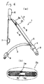
- an air belt 1 includes a shoulder belt 2, a lap belt 3, a buckle 4, a tongue 5, and an intermediate guide 6.
- the shoulder belt 2 extends diagonally from the right side of a passenger to the left side of the passenger.
- the lap belt 3 extends from the right side of a passenger to the left side.
- the buckle 4 is arranged, for example, on the vehicle floor.
- the tongue 5 is engaged with the buckle 4 when fastening the seat belt.
- the intemediate guide 6 guides the shoulder belt 2.
- the shoulder belt 2 includes a normal belt 2a which is an ordinary seat belt, and a bag-like belt 2b, which is connected to one end of the normal belt 2a.
- the normal belt 2a slides freely through the intermediate guide 6.
- the other end of the normal belt 2a is connected with a seat belt retractor 7 having an emergency lock system (ELR)mechanism.
- ELR emergency lock system
- the normal belt 2a is wound into the seat belt retractor 7.
- the bag-like belt 2b is located at a portion that contacts a passenger and is connected with one end of the tongue 5. The opposite end of the tongue 5 is not connected with the normal belt 2a.
- the lap belt 3 is formed by a normal belt, which is an ordinary seat belt. One end of the lap belt 3 is connected with the tongue 5. The other end of the lap belt 3 is connected with the seat belt retractor 8 (ELR).
- the buckle 4 is connected with a gas generator 9, which generates high pressure gas during emergencies, such as when a collision occurs.
- the gas generated by the gas generator 9 flows toward the bag-like belt 2b through a passage extending through the tongue 5 and the buckle 4.
- the bag-like belt portion 2b of the shoulder belt 2 has a body 2c.
- the body 2c for example, may be folded and covered by a cover 2d, as shown by the solid line in Fig.6(b).
- the sides of the cover 2d are sewed to each other such that a stitching 2e is formed. This keeps the shoulder belt 2 in a strip-like state under normal situations.
- the stitching 2e of the cover 2d is easily opened by the inflation force of the shoulder belt 2 when the gas generator 9 is actuated.
- the bag-like belt 2b inflates, as shown by the dashed line in Fig. 6(b).
- the first objective of the present invention is to provide an air belt device that discharge gas sideward or downward, if a gas generator is actuated with the tongue and buckle in a separated state.
- a second objective of the present invention is to provide an air belt device which prevents foreign matters from entering buckle.
- the present invention provides an air belt device including an inflatable air belt, a tongue to which an end of the air belt is connected, a buckle engagable with the tongue, gas passages respectively formed within the buckle and the tongue and a gas generating device for supplying gas to the gas passage of the buckle, said air belt device being characterized in that said tongue includes cylindrical plugs each having the gas passage therein, aid buckle includes plug receiving bores each receiving the plug and having a check door inwardly openable based on reception of the plug and outwardly unopenable, said buckle includes a gas release port for discharging the gas from the gas supplying device downward or sideward, and said gas is introduced into the plug upon the operation of the gas generating device in a tongue-connecting state in which the plug is inserted in the buckle, and released from the gas release port upon the operation of the gas generating device when the check door is in a closed position and the tongue is separated from the buckle.
- an tongue receiving opening of the buckle is closed with a check door, when the tongue is not engaged with the buckle. This prevents foreign matters such as dust, dirt and sand from entering the inside of the buckle. If foreign matters in small sizes should enter the inside of the buckle, these foreign matters can be discharged from a relief ports. When each relief port is arranged in the downward direction under the buckle, the foreign matters that enter the inside of the buckle fall down from the relief port.
- each of said ducts includes a gas inlet and a gas outlet, wherein said gas outlet is located in the vicinity of the associated plug receiving bore, each of said valves is disposed in the gas outlet of the duct, wherein said valve is open based on gas pressure and closed without load of the gas pressure; and said plug received in the buckle and the gas outlet of the duct are capable of communicating each other when the tongue is received in the buckle.
- said valve comprises a plurality of shoulder portions each deformable to open the gas outlet based on the gas pressure.
- each of said shoulder portion has a distal end entering the plug received in the buckle when the shoulder portion is deformed by the gas pressure in case the tongue is coupled to the buckle.
- the shoulder portions having ends in the plug causes the connecting portion of the duct and the plug to be covered by the shoulder portions, thus, the gas come out from the duct flows smoothly into the plug.
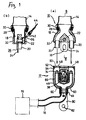
- Fig. 1(b) is an enlarged cross-sectional view of Fig. 1(a) taken along line B-B;
- Fig. 2 is an enlarged cross-sectional view showing the buckle;
- Fig. 3 is a cross-sectional view showing the engagement between the tongue and the buckle;
- Fig. 4 is a cross-sectionalo view showing the buckle separated from the tongue when a gas generator is actuated;
- Fig. 5(a) is a perspective view showing the buckle with gas flowing when the gas generator is actuated while the buckle is engaged with the tongue;
- Fig. 5(b) is a perspective view showing the buckle with gas flowing when the gas generator is actuated while the buckle is not engaged with the tongue;
- Fig. 6 is a perspective view showing an ordinary seat belt configuration.
- An air belt device includes a tongue 10, a buckle 12, a gas generator 16, and other parts.
- the rear end of the tongue 10 is connected with an air belt 14.
- the buckle 12 is inserted into the tongue 10.
- the gas generator 16 supplies gas to the buckle 12 through a hose 15.
- the tongue 10 includes a tongue base 18, hollow cylindrical plugs 20, a tongue plate 24, an anchor 26, rings 28, 30, a plastic cover 32, etc.
- the tongue base 18 is hollow.
- the hollow cylindrical plugs 20 protrude from the front end of the tongue base 18.
- the tongue plate 24 and the anchor 26 are each connected with the tongue base 18 by a connecting pin 22.
- the rings 28, 30 fix the air belt device 14 to the torque base 18.
- the plastic cover 32 covers the tongue base 18.
- a latch hole 36 of the tongue plate 24 is engaged with a latch of a latch mechanism 38 housed in the buckle 12.
- the latch is disengaged from the latch hole 36 by pressing a button 40 arranged on the buckle 12.
- the tongue plate 24 is forcibly separated from the buckle 12 by a spring (not shown).
- a hole 42 is defined in the anchor 26.
- a lap belt 44 is connected with the anchor 26 by inserting one end of the lap belt 44 into the hole 42 of the anchor 26.
- the rear end of the lap belt 44 is arranged so that the lap belt 44 is wound into a seat belt retractor.
- the air belt device 14 constitutes a portion of the seat belt.
- the rear end of the air belt 14 is engaged with the front end of a webbing which constitutes a portion of the shoulder belt.
- the rear end of the webbing is arranged so that the webbing is wound into the seat belt retractor.
- the buckle 12 is housed in a housing 46.
- An opening 34 for receiving the tongue plate 24 and bores 48 for receiving the plugs 20 are arranged in the front end of the housing 46.
- the plug receiving bores 48 are closed by check doors 50.
- Each check door 50 is pivotally connected with the housing 46 by a hinge pin 52 and is forced to a closed position by a spring 54.
- each check door 50 When each check door 50 is located at the closed position as shown in Figs. 1, 2, the distal end of the check door 50 is engaged with a stopper 56 arranged in the housing 46 so that the check door 50 is prevented from opening outward from the housing 46.
- Gas relief ports 60 and a port 62 for receiving a hose 15 are arranged at the rear (lower) end of the housing 46.
- a duct 66 is arranged in the housing 46.
- An gas inlet 68 of the duct 66 is inserted into the hose receiving port 62.
- An end of the hose 15 is fixed to the gas inlet 68 of the duct 66 by means of a ring 70.
- the inside of the housing 46 is devided into two parts.
- the duct 66 is bifurcated accordingly.
- a check cover 74 is arranged on a gas outlet 72 at the distal end of each part of the duct 66.
- Each check cover 74 includes a plurality of flexible pieces 76 that are fixed to the end faces of two separated parts of the duct 66, by applying an adhesive or by fusing the pieces 76.
- the flexible pieces 76 contact one another to close the gas outlets 72 when gas pressure is not applied to the flexible pieces 76.
- the distal ends of the flexible pieces 76 are separated from each other when gas pressure is applied so that each check cover 74 is opened as shown in Fig. 3, 4.
- each flexible piece 76 When the flexible pieces 76 are deformed to open with each plug 20 inserted into the corresponding plug receiving bore 48, as shown in Fig. 3, the distal end of each flexible piece 76 enters the plug 20.
- a bracket 80 is arranged to protrude downward from the housing 46.
- the buckle 12 is fixed to a body member of a vehicle by inserting a bolt into a hole 82 that is arranged in the bracket 80.
- the tongue 10 is engaged with the buckle 12 as shown in Fig. 2.
- the tongue plate 24 is inserted into the tongue receiving opening 34 and is latched with the latch mechanism 38.
- the distal ends of the plugs 20 enter the plug receiving bores 48 and enagages the gas outlets 72 of the ducts 66.
- the check doors 50 are pushed open into the housing 46 by the plugs 20.
- the gas generator 16 If the gas generator 16 is actuated when the tongue 10 is connected with the buckle as shown in Fig. 3, the gas passes through the hose 15 and the duct 66. The gas advances by deforming the flexible pieces 76 and by opening the check covers 74. The gas, then, flows into the insice of the air belt device 14. This inflates the air belt device 14.
- the distal ends of the flexible pieces 74 are inserted into the plugs 20.
- the portion connecting each plug 20 and the associated duct outlet 72 is encircled with the flexible pieces 74 so that the gas inside the ducts 76 can be smoothly provided into the air belt 14 through the plugs 20.
- the gas generator 16 If the gas generator 16 is erroneously actuated when the tongue 10 is separated from the buckle 12, the gas flows into the duct 66 through the hose 15. The gas, then, flows into the housing 46 by opening the flexible pieces 76. Since the check doors 50 are closed and do not open outward from the housing 46, the gas passes portions connecting the ducts 66 and the housing 46. The gas is finally discharged downward from the relief ports 60. Accordingly, if the gas generator 16 is erroneously actuated when the tongue is separated from the buckle, the gas is discharged from the buckle 12 downward. This prevents the passenger from being blasted by the gas.
- the check doors 50 close the plug receiving bores 48. Therefore, foreign matters are prevented from enter the housing 46 through the plug receiving bores 48. If holes are formed in the check doors 50 when the foreign matters enter the housing 46, the foreign matters would fall down from the relief ports 60. Moreover, the gas outlets 72 of the ducts 66 are closed by the check covers 74 so that foreign matters can not enter the ducts 66.
- the relief ports 60 open downward under the housing 46.
- the relief ports 60 may open sideways or diagonally downward.
- the gas is discharged downward. This ensures that the gas discharged from the relief ports is prevented from being blasted against a passenger.
- the foreign matters fall down from the relief ports 60, as described above.
Landscapes
- Engineering & Computer Science (AREA)
- Mechanical Engineering (AREA)
- Physics & Mathematics (AREA)
- Fluid Mechanics (AREA)
- Automotive Seat Belt Assembly (AREA)
- Air Bags (AREA)
Applications Claiming Priority (3)
| Application Number | Priority Date | Filing Date | Title |
|---|---|---|---|
| JP236908/97 | 1997-09-02 | ||
| JP23690897 | 1997-09-02 | ||
| JP23690897A JP3433654B2 (ja) | 1997-09-02 | 1997-09-02 | エアベルト装置 |
Publications (3)
| Publication Number | Publication Date |
|---|---|
| EP0908358A2 true EP0908358A2 (fr) | 1999-04-14 |
| EP0908358A3 EP0908358A3 (fr) | 2000-04-05 |
| EP0908358B1 EP0908358B1 (fr) | 2004-04-28 |
Family
ID=17007544
Family Applications (1)
| Application Number | Title | Priority Date | Filing Date |
|---|---|---|---|
| EP98116550A Expired - Lifetime EP0908358B1 (fr) | 1997-09-02 | 1998-09-02 | Ceinture de sécurité gonflable |
Country Status (4)
| Country | Link |
|---|---|
| US (1) | US6062597A (fr) |
| EP (1) | EP0908358B1 (fr) |
| JP (1) | JP3433654B2 (fr) |
| DE (1) | DE69823447T2 (fr) |
Cited By (3)
| Publication number | Priority date | Publication date | Assignee | Title |
|---|---|---|---|---|
| EP0960787A1 (fr) * | 1998-05-27 | 1999-12-01 | Takata Corporation | Languette pour coussin de sécurité gonflable et coussin de sécurité gonflable |
| DE10225032A1 (de) * | 2002-06-06 | 2004-01-08 | Autoliv Development Ab | Vorrichtung zum Befestigen eines Gassackeinfüllschlauches an einem Gasgenerator |
| WO2010051924A1 (fr) * | 2008-11-04 | 2010-05-14 | Autoliv Development Ab | Ceinture de sécurité gonflable |
Families Citing this family (15)
| Publication number | Priority date | Publication date | Assignee | Title |
|---|---|---|---|---|
| US6109647A (en) * | 1997-12-15 | 2000-08-29 | Honda Giken Kogyo Kabushiki Kaisha | Seat-occupant restraining apparatus |
| DE69912886T2 (de) * | 1998-07-06 | 2004-09-02 | Takata Corp. | Sicherheitsgurt für ein Kraftfahrzeug |
| JP3899723B2 (ja) * | 1999-03-10 | 2007-03-28 | タカタ株式会社 | エアベルト装置 |
| JP4527268B2 (ja) * | 2000-03-02 | 2010-08-18 | タカタ株式会社 | エアベルト用係止装置 |
| US6471243B1 (en) | 2000-09-07 | 2002-10-29 | Trw Vehicle Safety Systems Inc. | Inflation mechanism for inflatable seat belt |
| US6974153B2 (en) * | 2002-04-25 | 2005-12-13 | Diacel Chemical Industries, Ltd. | Gas generator for an air belt apparatus and air belt apparatus |
| JP4734933B2 (ja) * | 2004-02-27 | 2011-07-27 | タカタ株式会社 | 車両乗員保護システムおよびインフレータ |
| JP2007008219A (ja) * | 2005-06-28 | 2007-01-18 | Takata Corp | 乗員拘束装置 |
| JP4452676B2 (ja) * | 2005-11-10 | 2010-04-21 | トヨタ自動車株式会社 | 車両用エアベルト装置 |
| JP4923529B2 (ja) * | 2005-11-14 | 2012-04-25 | タカタ株式会社 | 乗員拘束装置 |
| JP4923531B2 (ja) * | 2005-11-15 | 2012-04-25 | タカタ株式会社 | エアベルト装置 |
| EP2303645B1 (fr) * | 2008-06-20 | 2015-07-15 | Ford Global Technologies, LLC | Système de ceinture de sécurité gonflable |
| US10479162B2 (en) * | 2017-12-07 | 2019-11-19 | Ford Global Technologies, Llc | Vehicle seat belt having tubes for air delivery |
| US10569735B2 (en) * | 2017-12-07 | 2020-02-25 | Ford Global Technologies, Llc | Vehicle seat belt system having uniform air delivery |
| US10442392B2 (en) | 2017-12-07 | 2019-10-15 | Ford Global Technologies, Llc | Vehicle seat belt system having air distribution manifold |
Family Cites Families (13)
| Publication number | Priority date | Publication date | Assignee | Title |
|---|---|---|---|---|
| BE756451A (fr) * | 1970-02-21 | 1971-03-01 | Rutzki Edith | Ceinture de securite |
| US3861712A (en) * | 1970-12-28 | 1975-01-21 | Nissan Motor | Apparatus for deflating an inflatable occupant restraint device |
| US3801156A (en) * | 1971-11-15 | 1974-04-02 | H Granig | Safety-belt |
| US3791670A (en) * | 1972-09-21 | 1974-02-12 | Allied Chem | Band buckle for use with inflatable seat belts |
| US3897081A (en) * | 1972-11-29 | 1975-07-29 | Allied Chem | Vehicle safety system |
| US3929348A (en) * | 1974-02-13 | 1975-12-30 | Allied Chem | Tongue for inflataband |
| DE2813285A1 (de) * | 1978-03-28 | 1979-10-11 | Bruno Savignano | Sicherheitsgurte fuer kraftfahrzeuge |
| JP3057112B2 (ja) * | 1991-09-24 | 2000-06-26 | タカタ株式会社 | インフレータブルシートベルト装置 |
| JP3057116B2 (ja) * | 1991-10-21 | 2000-06-26 | タカタ株式会社 | インフレータブルシートベルト装置 |
| US5288104A (en) | 1992-11-09 | 1994-02-22 | Johnny Chen | Buffering safe device in vehicles |
| US5597178A (en) * | 1994-08-18 | 1997-01-28 | Hardin, Jr.; Paul W. | Seatbelt airbag |
| US5765869A (en) * | 1996-09-06 | 1998-06-16 | Huber; John F. | Automatically tightened seatbelt |
| JPH1178781A (ja) * | 1997-09-02 | 1999-03-23 | Takata Kk | エアベルト装置 |
-
1997
- 1997-09-02 JP JP23690897A patent/JP3433654B2/ja not_active Expired - Fee Related
-
1998
- 1998-09-02 US US09/145,295 patent/US6062597A/en not_active Expired - Fee Related
- 1998-09-02 EP EP98116550A patent/EP0908358B1/fr not_active Expired - Lifetime
- 1998-09-02 DE DE69823447T patent/DE69823447T2/de not_active Expired - Fee Related
Cited By (5)
| Publication number | Priority date | Publication date | Assignee | Title |
|---|---|---|---|---|
| EP0960787A1 (fr) * | 1998-05-27 | 1999-12-01 | Takata Corporation | Languette pour coussin de sécurité gonflable et coussin de sécurité gonflable |
| DE10225032A1 (de) * | 2002-06-06 | 2004-01-08 | Autoliv Development Ab | Vorrichtung zum Befestigen eines Gassackeinfüllschlauches an einem Gasgenerator |
| DE10225032B4 (de) * | 2002-06-06 | 2006-02-09 | Autoliv Development Ab | Vorrichtung zum Befestigen eines Gassackeinfüllschlauches an einem Gasgenerator |
| WO2010051924A1 (fr) * | 2008-11-04 | 2010-05-14 | Autoliv Development Ab | Ceinture de sécurité gonflable |
| US8366147B2 (en) | 2008-11-04 | 2013-02-05 | Autoliv Development Ab | Inflatable safety belt |
Also Published As
| Publication number | Publication date |
|---|---|
| JPH1178780A (ja) | 1999-03-23 |
| EP0908358B1 (fr) | 2004-04-28 |
| DE69823447D1 (de) | 2004-06-03 |
| DE69823447T2 (de) | 2005-03-03 |
| EP0908358A3 (fr) | 2000-04-05 |
| JP3433654B2 (ja) | 2003-08-04 |
| US6062597A (en) | 2000-05-16 |
Similar Documents
| Publication | Publication Date | Title |
|---|---|---|
| EP0908358B1 (fr) | Ceinture de sécurité gonflable | |
| US5346250A (en) | Inflatable seat belt unit | |
| EP2303645B1 (fr) | Système de ceinture de sécurité gonflable | |
| US5899485A (en) | Air bag module with simplified manifold | |
| US6971667B2 (en) | Glove compartment airbag system | |
| CA2080987A1 (fr) | Ceinture de securite gonflable | |
| US6168195B1 (en) | Occupant protecting device | |
| US7073235B2 (en) | Non-inertial release safety restraint belt buckle systems | |
| US6142512A (en) | Air belt system | |
| US6145873A (en) | Air belt device | |
| US6615461B2 (en) | Tongue of inflatable belt device | |
| JP2001315617A (ja) | エアベルト用係止装置 | |
| US6168196B1 (en) | Tongue for an inflatable belt and inflatable belt device | |
| EP0901943A2 (fr) | Dispositif de ceinture de sécurité gonflable | |
| EP0960786B1 (fr) | Languette pour une ceinture gonflable et ceinture gonflable | |
| JP3724195B2 (ja) | エアベルト装置 | |
| JP2000052918A (ja) | 乗員保護装置 | |
| JPH11348722A (ja) | エアベルト装置 | |
| JPH1134776A (ja) | 乗員保護装置 |
Legal Events
| Date | Code | Title | Description |
|---|---|---|---|
| PUAI | Public reference made under article 153(3) epc to a published international application that has entered the european phase |
Free format text: ORIGINAL CODE: 0009012 |
|
| AK | Designated contracting states |
Kind code of ref document: A2 Designated state(s): DE FR GB |
|
| AX | Request for extension of the european patent |
Free format text: AL;LT;LV;MK;RO;SI |
|
| PUAL | Search report despatched |
Free format text: ORIGINAL CODE: 0009013 |
|
| AK | Designated contracting states |
Kind code of ref document: A3 Designated state(s): AT BE CH CY DE DK ES FI FR GB GR IE IT LI LU MC NL PT SE |
|
| AX | Request for extension of the european patent |
Free format text: AL;LT;LV;MK;RO;SI |
|
| 17P | Request for examination filed |
Effective date: 20000523 |
|
| AKX | Designation fees paid |
Free format text: DE FR GB |
|
| GRAP | Despatch of communication of intention to grant a patent |
Free format text: ORIGINAL CODE: EPIDOSNIGR1 |
|
| RTI1 | Title (correction) |
Free format text: INFLATABLE SAFETY BELT |
|
| GRAS | Grant fee paid |
Free format text: ORIGINAL CODE: EPIDOSNIGR3 |
|
| GRAA | (expected) grant |
Free format text: ORIGINAL CODE: 0009210 |
|
| AK | Designated contracting states |
Kind code of ref document: B1 Designated state(s): DE FR GB |
|
| REG | Reference to a national code |
Ref country code: GB Ref legal event code: FG4D |
|
| REF | Corresponds to: |
Ref document number: 69823447 Country of ref document: DE Date of ref document: 20040603 Kind code of ref document: P |
|
| ET | Fr: translation filed | ||
| PLBE | No opposition filed within time limit |
Free format text: ORIGINAL CODE: 0009261 |
|
| STAA | Information on the status of an ep patent application or granted ep patent |
Free format text: STATUS: NO OPPOSITION FILED WITHIN TIME LIMIT |
|
| 26N | No opposition filed |
Effective date: 20050131 |
|
| PGFP | Annual fee paid to national office [announced via postgrant information from national office to epo] |
Ref country code: DE Payment date: 20070830 Year of fee payment: 10 |
|
| PGFP | Annual fee paid to national office [announced via postgrant information from national office to epo] |
Ref country code: GB Payment date: 20070829 Year of fee payment: 10 |
|
| PGFP | Annual fee paid to national office [announced via postgrant information from national office to epo] |
Ref country code: FR Payment date: 20070914 Year of fee payment: 10 |
|
| GBPC | Gb: european patent ceased through non-payment of renewal fee |
Effective date: 20080902 |
|
| REG | Reference to a national code |
Ref country code: FR Ref legal event code: ST Effective date: 20090529 |
|
| PG25 | Lapsed in a contracting state [announced via postgrant information from national office to epo] |
Ref country code: DE Free format text: LAPSE BECAUSE OF NON-PAYMENT OF DUE FEES Effective date: 20090401 |
|
| PG25 | Lapsed in a contracting state [announced via postgrant information from national office to epo] |
Ref country code: FR Free format text: LAPSE BECAUSE OF NON-PAYMENT OF DUE FEES Effective date: 20080930 |
|
| PG25 | Lapsed in a contracting state [announced via postgrant information from national office to epo] |
Ref country code: GB Free format text: LAPSE BECAUSE OF NON-PAYMENT OF DUE FEES Effective date: 20080902 |