EP0908537B1 - Procédé et dispositif pour le placage sélectif d'une aube de turbine - Google Patents
Procédé et dispositif pour le placage sélectif d'une aube de turbine Download PDFInfo
- Publication number
- EP0908537B1 EP0908537B1 EP98117822A EP98117822A EP0908537B1 EP 0908537 B1 EP0908537 B1 EP 0908537B1 EP 98117822 A EP98117822 A EP 98117822A EP 98117822 A EP98117822 A EP 98117822A EP 0908537 B1 EP0908537 B1 EP 0908537B1
- Authority
- EP
- European Patent Office
- Prior art keywords
- airfoil
- fixture
- root portion
- airfoils
- tip
- Prior art date
- Legal status (The legal status is an assumption and is not a legal conclusion. Google has not performed a legal analysis and makes no representation as to the accuracy of the status listed.)
- Expired - Lifetime
Links
Images


Classifications
-
- C—CHEMISTRY; METALLURGY
- C25—ELECTROLYTIC OR ELECTROPHORETIC PROCESSES; APPARATUS THEREFOR
- C25D—PROCESSES FOR THE ELECTROLYTIC OR ELECTROPHORETIC PRODUCTION OF COATINGS; ELECTROFORMING; APPARATUS THEREFOR
- C25D17/00—Constructional parts, or assemblies thereof, of cells for electrolytic coating
- C25D17/06—Suspending or supporting devices for articles to be coated
-
- C—CHEMISTRY; METALLURGY
- C25—ELECTROLYTIC OR ELECTROPHORETIC PROCESSES; APPARATUS THEREFOR
- C25D—PROCESSES FOR THE ELECTROLYTIC OR ELECTROPHORETIC PRODUCTION OF COATINGS; ELECTROFORMING; APPARATUS THEREFOR
- C25D5/00—Electroplating characterised by the process; Pretreatment or after-treatment of workpieces
- C25D5/02—Electroplating of selected surface areas
- C25D5/022—Electroplating of selected surface areas using masking means
Definitions
- the present invention resides in an improved process and apparatus for the electroplating of airfoils used in turbines and the like.
- Airfoils which are used in jet engine environments, are generally required to have the tip portion thereof coated with a wear-resistant and corrosion-resistant material.
- Typical coating processes and apparatus require the masking of the airfoils in a coating fixture prior to the electroplating of a protective material on the tip portion of the airfoil blade.
- the fixtures previously used suffer from a number of disadvantages. These disadvantages include chemical contamination due to dragout in the plating baths, clumsiness of assembly of the supporting fixture for the airfoils, and limited capacity, that is limited number of airfoils processed per batch.
- the US-A 5 607 561 discloses a method and an apparatus for forming abrasive surfaces on the tips of a plurality of workpieces such as the tips of gas turbine airfoil blades.
- the method comprises the steps of providing a mechanical masking device having a plurality of openings arranged around the circumference of the device, installing an array containing a plurality of workpieces to be coated within the mechanical masking device so that portions of the workpieces including the tips thereof extend through the openings, immersing the mechanical masking device with the installed array of workpieces in a tank containing a plating bath with a matrix material and an abrasive grit material in slurry form so that the workpieces lie in a substantially horizontal plane and applying a current through the plating bath to form the abrasive surfaces of the tips of the workpieces.
- the mechanical masking device protects portions of the array form the coating operation.
- a barrier device is also used to confine the abrasive grit material within
- WO-A 95 17 535 Another method and apparatus for producing abrasive tips on compressor or turbine rotor blades is known by WO-A 95 17 535.
- This production includes electrolytic or electroless deposition in which the blades are mounted in a hollow jig with the tips of the blades extending through sealed openings in the jig and abrasive tips are formed on the tips.
- the parts of the blades within the hollow jig are isolated from the electrolyte without the need for wax masking.
- the jig may be cylindrical with the blades extending radially through circumferential rows of apertures.
- the present invention is drawn to an improved process for electroplating the tip portion of an airfoil and an improved apparatus for use in the process.
- the process of the present invention for electroplating the tip portion of an airfoil comprises providing an airfoil having a root portion and a blade portion, the blade portion having a tip remote from the root portion; coating at least part of the blade portion including the tip with an insulating material to produce a partially insulated coated airfoil; removing the insulating material from the tip of the blade portion to be electroplated; mounting the airfoil with exposed tip in a fixture wherein the airfoil contacts an electrical contact;
- the fixture having a configured root portion and a blade portion to be electroplated comprises an elongated base member and grip means supported on the elongated base member for holding the airfoils, said grip means comprises a flexible material defining a plurality of configured slots for receiving the configured root portion of the airfoils and gripping same, each of the configured slots is provided with an electrical contact biased so as to contact the root portion of the airfoil when the airfoil is received in the configured slot; immersing the fixture with airfoil in
- a fixture for supporting a plurality of airfoils which comprises an elongated base member; grip means supported on the elongated base member for holding the airfoils, said grip means comprises a flexible material defining a plurality of configured slots for receiving the configured root portion of the airfoils and gripping same, each of the configured slots is provided with an electrical contact biased so as to contact the root portion of the airfoil when the airfoil is received in the configured slot.
- the fixture is mounted on a rotatable carousel having a plurality of sides wherein each of the plurality of sides is provided with at least one shaped insert for receiving the bottom surface of the fixture.
- an airfoil 10 has a root portion 12 and a blade portion 14.
- the blade portion 14 is integral with the root portion 12 and has a tip portion 16 which, depending on the environment to which the airfoil will be exposed, is coated with a wear-resistant, corrosion-resistant coating.
- the blade portion 14 of the airfoil is coated with an insulating material.
- the insulating material is preferably an UV curable material for minimum cycle time; however, it should be appreciated that other insulating materials known in the prior art may be employed such as vinyl ester, polyester, polyimide, epoxy, et al.
- the preferred UV curable materials are manufactured and sold by Dymax Corporation under product designations 29601 through 29608.
- the portion of the blade which must be coated with the insulating material is the portion immediately adjacent the tip portion of the airfoil which will be subsequently electroplated.
- the root portion of the blade is not insulated as it is the root portion which will provide the electrical contact for the airfoil during electroplating. Accordingly, the blade may be coated with the insulating material by immersing the blade in a bath of the insulating material. In the case of the preferred UV-curable insulating material mentioned above, the blade is immersed in same so as to cover the critical portion of the blade and thereafter removed from the bath. The UV insulating material is then cured so as to form a hardened insulating coating on the blade.
- the tip portion 16 of the airfoil 10 is prepared for electroplating by removing the layer of insulating material therefrom.
- This tip preparation is carried out by, for example, mechanically removing the insulating material by grinding or the like.
- other methods may be used as known in the art such as chemical stripping.
- the tip portion of the blade should be masked prior to exposing the blade to the insulating material bath thereby eliminating the need to remove the insulating material from the tip portion.
- masking has proved to be quite difficult and, therefore, not preferred for the process of the present invention.
- the airfoil prepared in the manner described above is now ready to have the tip portion electroplated.
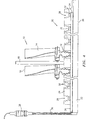
- a plating fixture 20 in accordance with the present invention for supporting a plurality of airfoils 10 for electroplating.
- the fixture 20 includes an elongated base member 22 and a root support portion 24 for gripping and supporting the airfoil as described below.
- the base portion 22 is formed of a relatively hard insulating material such as silicone, neoprene, acrylic, et al.
- the underside 26 of the elongated base member 22 is shaped to correspond to the shape of a carousel (see Figure 2) for supporting the fixture during electroplating in a manner to be described hereinbelow.
- the root support portion 24 is supported on the elongated base member 22 and includes a plurality of gripping slots 28 each for gripping and holding the root portion of an airfoil. As can be seen with reference to Figure 4, each of the gripping slots 28 has an internal configuration 30 on the opposed sidewalls for each slot similar to the configuration of the root portion for receiving same.
- the root support portion 24 is also formed of an electrical insulating material; however, the material must have sufficient resiliency so as to grip the root portion of the airfoil and hold same in the fixture. Accordingly, the size of the gripping slots 28 must be smaller than the root portion dimension being gripped. Suitable materials from which the root support portion 24 may be formed include any of a number of castable silicone rubbers.
- each of the gripping slots 28 are electrical contacts 32 which, as can be seen in Figure 4, are connected to a central electrical contacting member 34 provided on plating fixture 20 and supported and insulated by sealant coating 15 as described in detail hereinbelow.
- Contacting member 34 leads to upright 36 which is provided with connection 38 for attachment to a source of electricity as will be described.
- Fixture 20 further includes a rod 40 which serves as a support for the fixture when immersed in the sealing bath as described hereinbelow.
- the loaded fixture is immersed in a sealing bath to encase the fixture 20 and at least a portion of the blade portion of the airfoil coated with the insulating material so as to leave exposed only the tip portion of the airfoil to be electroplated.
- the fixture is supported in the sealing bath by means of rod 40.
- the airfoil 10 after immersion in the sealing bath has an exposed tip portion 16, a blade portion 14' adjacent the exposed tip portion which is coated with an insulating material (preferably an insulated curable material) and a sealant coating 15 which envelopes the fixture, root portion of the airfoil and a portion of the blade portion wherein the sealant coating overlaps the insulating material so as to leave only the tip of the blade exposed for electroplating.
- the sealant material is preferably a thermoplastic material which can be heated to a liquid state to form the bath and air cured to solidify. The material must remain solid during the plating process.
- sealant when exposed to elevated temperatures in excess of the temperatures of the plating solutions during plating, the sealant should soften so as to be easily removed after electroplating.
- Suitable sealant materials include any number of hot melt thermoplastic coatings or adhesives that can be polyolefin, polyemide or acrylic based. A preferred material is manufactured and sold by Thermo Cote, Inc. under designation Thermo Cote N-4 (55).
- Carousel 50 has a central cylindrical portion 52 provided on its end with wall 54.
- the walls 54 are substantially square in shape and having four side surfaces 56 which are provided with a plurality of shaped recesses 58.
- the shaped recesses are formed with a shape corresponding to the shape of the underside 26 of elongated base member 22 for receiving base member 22 in a stable manner.
- each side surface 56 is provided with three shaped recesses 58. It should be appreciated that the number may vary depending on the size of the plating tanks.
- the fixtures 20 are held in place in the shaped recesses 56 by brackets 60 secured to the side surfaces 56 of the walls 54 by bolts 62 or the like.
- the carousel 50 is loaded, it is loaded in the electroplating solution and the electroplating process is carried out in a known manner as is known in the art.
- the advantages of the carousel assembly of the present invention are the following: substantial elimination of plating bath contamination, ease of assembly of airfoil support apparatus and reduction of cycle time.
- the carousel 50 is removed from the plating solution and the fixtures are removed from the carousel (see Figure 1).
- the fixtures are thereafter heated to soften the sealant material.
- the fixtures are heated to a temperature of 230°F (110°C) and heated for sufficient time, about 15 minutes, to soften the sealant material so that it may be easily peeled off the fixture and airfoil.
- the airfoils are then removed from the fixtures for final use.
Landscapes
- Chemical & Material Sciences (AREA)
- Engineering & Computer Science (AREA)
- Chemical Kinetics & Catalysis (AREA)
- Electrochemistry (AREA)
- Materials Engineering (AREA)
- Metallurgy (AREA)
- Organic Chemistry (AREA)
- Electroplating Methods And Accessories (AREA)
- Chemically Coating (AREA)
Claims (17)
- Un procédé pour métalliser par galvanisation une partie d'une ailette, le procédé comprenant les étapes consistant :à fournir une ailette présentant une portion de pied ou de racine et une portion de lame, la portion de lame ayant une extrémité éloignée de la portion de pied ;à revêtir au moins une partie de la portion de lame comprenant l'extrémité avec un matériau isolant pour produire une ailette revêtue partiellement isolée ;à enlever le matériau isolant de l'extrémité de la portion de lame à métalliser par galvanisation ; à monter l'ailette avec l'extrémité exposée dans un montage de fixation dans lequel l'ailette est en contact avec un contact électrique ;le montage de fixation pour une ailette munie d'une portion à configuration de pied et une portion de lame à métalliser par galvanisation comprend un organe de base allongé et des moyens de saisie supportés sur l'organe de base allongé pour porter les ailettes, lesdits moyens de saisie comprenant un matériau flexible définissant une pluralité de fentes configurées pour recevoir la partie à configuration de pied des ailettes et à saisir ces dernières, chacune des fentes configurées étant munie d'un contact électrique sollicité de façon à venir en contact avec la portion de pied de l'ailette lorsque l'ailette est reçue dans la fente de forme ;à immerger le montage de fixation avec l'ailette dans un bain d'étanchéité de façon à envelopper de façon étanche le montage de fixation et au moins une partie de l'ailette revêtue et isolée en laissant l'extrémité exposée pour former un ensemble de montage de fixation avec un revêtement partiel d'étanchéité ;à immerger l'ensemble de montage de fixation dans un bain de métallisation par galvanisation pour métalliser par galvanisation la pointe de l'ailette ; et à retirer l'ensemble de montage de fixation du bain.
- Un procédé selon la revendication 1, comprenant l'étape consistant à munir le montage de fixation d'une pluralité de moyens de saisie pour recevoir la portion de pied d'une pluralité d'ailettes.
- Un procédé selon la revendication 1 ou 2, dans lequel les moyens de saisie comportent deux parois latérales exposées pour saisir le pied de chacune parmi une pluralité d'ailettes et une base munie du contact électrique qui est en contact avec la portion de pied de chacune parmi la pluralité d'ailettes.
- Un procédé selon la revendication 3, dans lequel chacune des parois latérales des moyens de saisie présente une configuration apte à venir en contact avec une configuration correspondante sur la portion de pied de l'ailette pour maintenir fermement en place l'ailette.
- Un procédé selon la revendication 2, comprenant le chargement d'une pluralité de montages de fixation après le revêtement d'étanchéité sur un chariot à plateau tournant de métallisation par galvanisation.
- Un procédé selon l'une des revendications 1 à 5, dans lequel le matériau isolant est un matériau polymérisable aux UV et comporte l'étape consistant à polymériser aux UV l'ailette partiellement revêtue avant d'enlever le revêtement de l'extrémité de la portion de lame de l'ailette.
- Un procédé selon l'une des revendications 1 à 6, dans lequel le bain d'étanchéité comporte un revêtement thermoplastique de colle thermofusible et comporte l'étape consistant à fixer le revêtement thermoplastique de colle thermofusible pour former un ensemble de fixation revêtu partiellement de produit étanche avant d'immerger l'ensemble de fixation dans le bain de métallisation par galvanisation.
- Un procédé selon l'une des revendications 1 à 7 comprenant l'étape consistant à exposer l'ensemble de fixation après la métallisation par galvanisation à une température élevée pour ramollir le revêtement d'étanchéité et ensuite enlever le revêtement d'étanchéité du montage de fixation.
- Un procédé selon la revendication 1, dans lequel la portion de pied de l'ailette est exempte de matériau isolant et/ou dans lequel le revêtement d'étanchéité recouvre au moins une partie du matériau isolant.
- Un montage de fixation pour supporter une pluralité d'ailettes présentant une portion à configuration de pied et une portion de lame à métalliser par galvanisation, qui comprend :un organe de base allongé ;des moyens de saisie supportés sur l'organe de base allongé pour porter les ailettes, lesdits moyens de saisie comprenant un matériau flexible définissant une pluralité de fentes configurées pour recevoir la portion à configuration de pied des ailettes et saisir cette portion à configuration de pied, chacune des fentes configurées étant munie d'un contact électrique sollicité de façon à venir en contact avec la portion de pied de l'ailette lorsque l'ailette est reçue dans la fente configurée.
- Un montage de fixation selon la revendication 10, dans lequel les fentes de forme comportent des parois latérales opposées et une paroi de fond et dans lequel les parois latérales opposées présentent une configuration propre à recevoir la partie à configuration de pied de l'ailette et la paroi de fond porte le contact électrique.
- Un montage de fixation selon la revendication 10 ou 11, comprenant en outre une tige de support s'étendant de façon sensiblement perpendiculaire à l'organe de base allongé.
- Un montage de fixation selon l'une des revendications 10 à 12, dans lequel lesdits moyens de saisie sont formés d'un matériau élastique isolant électrique.
- Un montage de fixation selon l'une des revendications 10 à 13, dans lequel le contact électrique dans chaque fente configurée est relié à un organe électrique central de contact s'étendant dans l'organe de base allongé.
- Un ensemble pour métalliser une pluralité d'ailettes comprend :un chariot rotatif à plateau tournant présentant une pluralité de faces dont chacune comporte au moins des moyens de réception à conformation particulière ;des moyens de montage de fixation selon la revendication 10 montés dans les moyens de réception sur les faces du chariot à plateau tournant, les moyens de montage de fixation comprenant une partie de base allongée munie d'une surface de fond correspondant aux moyens de réception à conformation particulière et une surface supérieure munie de moyens de saisie etau moins une ailette fixée aux dits moyens de saisie.
- Un ensemble selon la revendication 15, dans lequel lesdits moyens de saisie comprennent un matériau flexible définissant une pluralité de fentes configurées pour recevoir une portion à configuration de pied de la au moins une ailette, chacune des fentes configurées comportant un contact électrique, de façon à venir en contact avec une portion de pied de l'ailette lorsque cette dernière est reçue dans une fente configurée.
- Un ensemble selon la revendication 15 ou 16, dans lequel les fentes de forme comprennent des parois latérales opposées et une paroi de fond, dans lequel les parois latérales opposées présentent une configuration pour recevoir 1a portion à configuration de pied de l'ailette et la paroi de fond porte le contact électrique.
Applications Claiming Priority (2)
| Application Number | Priority Date | Filing Date | Title |
|---|---|---|---|
| US942452 | 1997-10-01 | ||
| US08/942,452 US5902471A (en) | 1997-10-01 | 1997-10-01 | Process for selectively electroplating an airfoil |
Publications (2)
| Publication Number | Publication Date |
|---|---|
| EP0908537A1 EP0908537A1 (fr) | 1999-04-14 |
| EP0908537B1 true EP0908537B1 (fr) | 2002-06-12 |
Family
ID=25478086
Family Applications (1)
| Application Number | Title | Priority Date | Filing Date |
|---|---|---|---|
| EP98117822A Expired - Lifetime EP0908537B1 (fr) | 1997-10-01 | 1998-09-19 | Procédé et dispositif pour le placage sélectif d'une aube de turbine |
Country Status (4)
| Country | Link |
|---|---|
| US (2) | US5902471A (fr) |
| EP (1) | EP0908537B1 (fr) |
| JP (1) | JP2939936B2 (fr) |
| DE (1) | DE69805929T2 (fr) |
Families Citing this family (16)
| Publication number | Priority date | Publication date | Assignee | Title |
|---|---|---|---|---|
| US6254756B1 (en) * | 1999-08-11 | 2001-07-03 | General Electric Company | Preparation of components having a partial platinum coating thereon |
| US6299749B1 (en) * | 1999-10-25 | 2001-10-09 | Molex Incorporated | Method of fabricating an electrical component |
| DE10149892A1 (de) * | 2001-10-10 | 2003-04-17 | Thorsten Koras | Verfahren zum partiellen Aufbringen einer Beschichtung auf eine Metalloberfläche mittels einer Oberflächenbehandlung |
| US6761807B2 (en) * | 2002-03-09 | 2004-07-13 | United Technologies Corporation | Molded tooling for use in airfoil stripping processes |
| EP1428982B1 (fr) * | 2002-12-06 | 2009-02-04 | ALSTOM Technology Ltd | Méthode pour déposer localement un revêtement de type MCrAlY |
| US7208046B1 (en) * | 2003-01-10 | 2007-04-24 | White Electronic Designs Corporation | Spray coating apparatus and fixtures |
| US7384522B2 (en) * | 2005-04-29 | 2008-06-10 | United Technologies Corporation | Ergonomic loading apparatus for electroplating processes |
| US20070034524A1 (en) * | 2005-08-12 | 2007-02-15 | United Technologies Corporation | Masking techniques for electrochemical stripping |
| CA2858188C (fr) * | 2011-12-08 | 2018-03-06 | Praxair S.T. Technology, Inc. | Ensemble monture d'outillage multifonction destine a etre utilise dans des operations associees a un revetement |
| WO2013086286A2 (fr) * | 2011-12-08 | 2013-06-13 | Prexair S. T. Technology, Inc. | Ensemble accessoire d'usinage pour une opération de revêtement |
| ES2859572T3 (es) | 2013-04-26 | 2021-10-04 | Howmet Corp | Electrodeposición del componente del perfil alar interno |
| CA2866479C (fr) | 2013-12-20 | 2021-08-17 | Will N. Kirkendall | Electroplacage de composant de turbine interne |
| PL416283A1 (pl) | 2016-02-26 | 2017-08-28 | General Electric Company | Wyrób z ulepszonym układem powłok oraz sposoby jego wytwarzania |
| US10570753B2 (en) | 2017-01-23 | 2020-02-25 | United Technologies Corporation | Apparatus and method for masking under platform areas of airfoil components |
| US10253417B2 (en) | 2017-01-30 | 2019-04-09 | United Technologies Corporation | System and method for applying abrasive grit |
| US20190194799A1 (en) | 2017-12-22 | 2019-06-27 | United Technologies Corporation | Line-of-sight coating fixture and apparatus |
Family Cites Families (9)
| Publication number | Priority date | Publication date | Assignee | Title |
|---|---|---|---|---|
| US4169020A (en) * | 1977-12-21 | 1979-09-25 | General Electric Company | Method for making an improved gas seal |
| US4256555A (en) * | 1978-05-30 | 1981-03-17 | Rolls Royce Limited | Electro-chemical-machining of aerofoil blades |
| DE3568065D1 (en) * | 1984-07-16 | 1989-03-09 | Bbc Brown Boveri & Cie | Process for the deposition of a corrosion-inhibiting layer, comprising protective oxide-forming elements at the base of a gas turbine blade, and a corrosion-inhibiting layer |
| GB2241506A (en) * | 1990-02-23 | 1991-09-04 | Baj Ltd | Method of producing a gas turbine blade having an abrasive tip by electrodepo- sition. |
| US5389228A (en) * | 1993-02-04 | 1995-02-14 | United Technologies Corporation | Brush plating compressor blade tips |
| US5486281A (en) * | 1993-10-15 | 1996-01-23 | United Technologies Corporation | Method for CBN tipping of HPC integrally bladed rotors |
| GB9326082D0 (en) * | 1993-12-21 | 1994-02-23 | Baj Coatings Ltd | Rotor blades |
| US5800695A (en) * | 1996-10-16 | 1998-09-01 | Chromalloy Gas Turbine Corporation | Plating turbine engine components |
| US5792267A (en) * | 1997-05-16 | 1998-08-11 | United Technologies Corporation | Coating fixture for a turbine engine blade |
-
1997
- 1997-10-01 US US08/942,452 patent/US5902471A/en not_active Expired - Lifetime
-
1998
- 1998-09-19 DE DE69805929T patent/DE69805929T2/de not_active Expired - Lifetime
- 1998-09-19 EP EP98117822A patent/EP0908537B1/fr not_active Expired - Lifetime
- 1998-10-01 JP JP10279944A patent/JP2939936B2/ja not_active Expired - Fee Related
-
1999
- 1999-03-15 US US09/268,186 patent/US6162335A/en not_active Expired - Lifetime
Also Published As
| Publication number | Publication date |
|---|---|
| DE69805929D1 (de) | 2002-07-18 |
| JP2939936B2 (ja) | 1999-08-25 |
| US6162335A (en) | 2000-12-19 |
| DE69805929T2 (de) | 2003-01-23 |
| US5902471A (en) | 1999-05-11 |
| EP0908537A1 (fr) | 1999-04-14 |
| JPH11158689A (ja) | 1999-06-15 |
Similar Documents
| Publication | Publication Date | Title |
|---|---|---|
| EP0908537B1 (fr) | Procédé et dispositif pour le placage sélectif d'une aube de turbine | |
| US5486281A (en) | Method for CBN tipping of HPC integrally bladed rotors | |
| KR102556923B1 (ko) | 웨이퍼 부착을 감소시키기 위해 통합된 탄성중합체 립시일 및 컵 하단부 | |
| KR0135609B1 (ko) | 반도체 장치 및 그 제조방법 | |
| US4931149A (en) | Fixture and a method for plating contact bumps for integrated circuits | |
| EP0975435B1 (fr) | Dispositif de revetement modulaire | |
| EP0690495B1 (fr) | Procédé de fabrication de diodes circulaires passivées par du verre | |
| GB2291432A (en) | Rotor Blades | |
| CN105603497A (zh) | 一种半导体晶圆电镀夹持装置、夹持方法及其电镀工艺 | |
| US20050230260A1 (en) | Plating apparatus and method | |
| CN1198873A (zh) | 对独立导体电路进行电镀的工艺 | |
| JP3647508B2 (ja) | メッキ用マガジン | |
| CA1267630A (fr) | Bande d'electrodeposition, et son emploi | |
| EP1087039A1 (fr) | Support pour metallisation de tranches | |
| JP3875200B2 (ja) | エアフォイルを支持するための治具 | |
| US20030141185A1 (en) | Contact assemblies, methods for making contact assemblies, and machines with contact assemblies for electrochemical processing of microelectronic workpieces | |
| US20060289302A1 (en) | Electroprocessing workpiece contact assemblies, and apparatus with contact assemblies for electroprocessing workpieces | |
| US5437724A (en) | Mask and grit container | |
| CN114243414A (zh) | 一种smp连接器的自动化去金搪锡工艺方法及使用的工装 | |
| WO2006023753A2 (fr) | Systeme d'amincissement de pieces de semi-conducteur | |
| CN115418688B (zh) | 铝排及其遮镀设备、工艺 | |
| US4975163A (en) | Electrochemical refractory metal stripper and parts cleaning process | |
| JP2957921B2 (ja) | バレル式電気めっき装置 | |
| JPS6014968A (ja) | 浸漬塗装方法 | |
| JPH10158815A (ja) | 静電チャック用被保持物配置部材及びその製造方法並びに静電チャック |
Legal Events
| Date | Code | Title | Description |
|---|---|---|---|
| PUAI | Public reference made under article 153(3) epc to a published international application that has entered the european phase |
Free format text: ORIGINAL CODE: 0009012 |
|
| AK | Designated contracting states |
Kind code of ref document: A1 Designated state(s): DE FR GB |
|
| AX | Request for extension of the european patent |
Free format text: AL;LT;LV;MK;RO;SI |
|
| 17P | Request for examination filed |
Effective date: 19990831 |
|
| AKX | Designation fees paid |
Free format text: DE FR GB |
|
| 17Q | First examination report despatched |
Effective date: 20000704 |
|
| GRAG | Despatch of communication of intention to grant |
Free format text: ORIGINAL CODE: EPIDOS AGRA |
|
| GRAG | Despatch of communication of intention to grant |
Free format text: ORIGINAL CODE: EPIDOS AGRA |
|
| GRAH | Despatch of communication of intention to grant a patent |
Free format text: ORIGINAL CODE: EPIDOS IGRA |
|
| GRAH | Despatch of communication of intention to grant a patent |
Free format text: ORIGINAL CODE: EPIDOS IGRA |
|
| GRAA | (expected) grant |
Free format text: ORIGINAL CODE: 0009210 |
|
| AK | Designated contracting states |
Kind code of ref document: B1 Designated state(s): DE FR GB |
|
| REG | Reference to a national code |
Ref country code: GB Ref legal event code: FG4D |
|
| REF | Corresponds to: |
Ref document number: 69805929 Country of ref document: DE Date of ref document: 20020718 |
|
| ET | Fr: translation filed | ||
| PLBE | No opposition filed within time limit |
Free format text: ORIGINAL CODE: 0009261 |
|
| 26N | No opposition filed |
Effective date: 20030313 |
|
| PGFP | Annual fee paid to national office [announced via postgrant information from national office to epo] |
Ref country code: FR Payment date: 20100921 Year of fee payment: 13 |
|
| REG | Reference to a national code |
Ref country code: FR Ref legal event code: ST Effective date: 20120531 |
|
| PG25 | Lapsed in a contracting state [announced via postgrant information from national office to epo] |
Ref country code: FR Free format text: LAPSE BECAUSE OF NON-PAYMENT OF DUE FEES Effective date: 20110930 |
|
| PGFP | Annual fee paid to national office [announced via postgrant information from national office to epo] |
Ref country code: GB Payment date: 20120919 Year of fee payment: 15 |
|
| PGFP | Annual fee paid to national office [announced via postgrant information from national office to epo] |
Ref country code: DE Payment date: 20120912 Year of fee payment: 15 |
|
| GBPC | Gb: european patent ceased through non-payment of renewal fee |
Effective date: 20130919 |
|
| REG | Reference to a national code |
Ref country code: DE Ref legal event code: R119 Ref document number: 69805929 Country of ref document: DE Effective date: 20140401 |
|
| PG25 | Lapsed in a contracting state [announced via postgrant information from national office to epo] |
Ref country code: GB Free format text: LAPSE BECAUSE OF NON-PAYMENT OF DUE FEES Effective date: 20130919 |
|
| PG25 | Lapsed in a contracting state [announced via postgrant information from national office to epo] |
Ref country code: DE Free format text: LAPSE BECAUSE OF NON-PAYMENT OF DUE FEES Effective date: 20140401 |