EP0908647B1 - Aufbau eines Hypoidgetriebes - Google Patents
Aufbau eines Hypoidgetriebes Download PDFInfo
- Publication number
- EP0908647B1 EP0908647B1 EP98119236A EP98119236A EP0908647B1 EP 0908647 B1 EP0908647 B1 EP 0908647B1 EP 98119236 A EP98119236 A EP 98119236A EP 98119236 A EP98119236 A EP 98119236A EP 0908647 B1 EP0908647 B1 EP 0908647B1
- Authority
- EP
- European Patent Office
- Prior art keywords
- hypoid
- gear
- ring gear
- toothed portion
- spring
- Prior art date
- Legal status (The legal status is an assumption and is not a legal conclusion. Google has not performed a legal analysis and makes no representation as to the accuracy of the status listed.)
- Expired - Lifetime
Links
Images





Classifications
-
- F—MECHANICAL ENGINEERING; LIGHTING; HEATING; WEAPONS; BLASTING
- F16—ENGINEERING ELEMENTS AND UNITS; GENERAL MEASURES FOR PRODUCING AND MAINTAINING EFFECTIVE FUNCTIONING OF MACHINES OR INSTALLATIONS; THERMAL INSULATION IN GENERAL
- F16H—GEARING
- F16H55/00—Elements with teeth or friction surfaces for conveying motion; Worms, pulleys or sheaves for gearing mechanisms
- F16H55/02—Toothed members; Worms
- F16H55/17—Toothed wheels
- F16H55/18—Special devices for taking up backlash
- F16H55/20—Special devices for taking up backlash for bevel gears
-
- B—PERFORMING OPERATIONS; TRANSPORTING
- B62—LAND VEHICLES FOR TRAVELLING OTHERWISE THAN ON RAILS
- B62D—MOTOR VEHICLES; TRAILERS
- B62D5/00—Power-assisted or power-driven steering
- B62D5/04—Power-assisted or power-driven steering electrical, e.g. using an electric servo-motor connected to, or forming part of, the steering gear
- B62D5/0409—Electric motor acting on the steering column
-
- Y—GENERAL TAGGING OF NEW TECHNOLOGICAL DEVELOPMENTS; GENERAL TAGGING OF CROSS-SECTIONAL TECHNOLOGIES SPANNING OVER SEVERAL SECTIONS OF THE IPC; TECHNICAL SUBJECTS COVERED BY FORMER USPC CROSS-REFERENCE ART COLLECTIONS [XRACs] AND DIGESTS
- Y10—TECHNICAL SUBJECTS COVERED BY FORMER USPC
- Y10T—TECHNICAL SUBJECTS COVERED BY FORMER US CLASSIFICATION
- Y10T74/00—Machine element or mechanism
- Y10T74/19—Gearing
- Y10T74/19623—Backlash take-up
-
- Y—GENERAL TAGGING OF NEW TECHNOLOGICAL DEVELOPMENTS; GENERAL TAGGING OF CROSS-SECTIONAL TECHNOLOGIES SPANNING OVER SEVERAL SECTIONS OF THE IPC; TECHNICAL SUBJECTS COVERED BY FORMER USPC CROSS-REFERENCE ART COLLECTIONS [XRACs] AND DIGESTS
- Y10—TECHNICAL SUBJECTS COVERED BY FORMER USPC
- Y10T—TECHNICAL SUBJECTS COVERED BY FORMER US CLASSIFICATION
- Y10T74/00—Machine element or mechanism
- Y10T74/19—Gearing
- Y10T74/1987—Rotary bodies
- Y10T74/19893—Sectional
- Y10T74/19907—Sound deadening
Definitions
- the present invention relates to a hypoid gear structure, and more particularly, relates to a hypoid gear structure having an excellent abnormal-sound prevention property.
- a technique for using a hypoid gear in a motor-driven power steering device is known.
- the hypoid gear is disposed as a decelerating mechanism between a rotation axis of an electric motor for providing an auxiliary force for steering and an output axis of a steering system.
- the rotation axis of the electric motor and the output axis of the steering system are coupled with each other by the hypoid gear structure which functions as a decelerating mechanism.
- Japanese Laid-Open Publication No. 7-232651 discloses that such a backlash produced at the engaging portion of gears can be appropriately controlled by adjusting the position at which a hypoid ring gear is attached in the vertical direction.
- the engagement between the hypoid ring gear and a hypoid pinion gear is adjusted so that an appropriate backlash is obtained at a correct meshed position between the hypoid ring gear and the hypoid pinion gear.
- This allows for smooth engagement therebetween.
- the hypoid gear structure receives a vibration and the like from the side of the tires (from the road surface), an abnormal sound such as a tooth striking sound may be generated due to a backlash even if the backlash is within an appropriate range.
- a hypoid gear structure includes: a hypoid ring gear disposed coaxially with a rotation axis; and a hypoid pinion gear provided with a rotation axis of an electric motor and engaging with the hypoid ring gear, wherein the hypoid ring gear includes a first toothed portion disposed on the inner side and a second toothed portion disposed on the outer side, and the first toothed portion is urged by a spring to press the hypoid pinion gear.
- the first toothed portion is coupled with the second toothed portion via the spring.
- An outer periphery of the first toothed portion is shaped so as to be kept apart from an inner periphery of the second toothed portion.
- the first toothed portion may be shaped so as to be in a correct engagement with the hypoid pinion gear in a state where the first toothed portion and the second toothed portion is meshed with the hypoid pinion gear with the spring being bent.
- the spring may be a plate spring having a ring portion, and a rotation regulating portion for regulating the rotation of the plate spring with respect to the second toothed portion is formed at an inner periphery of the plate spring.
- the first toothed portion may be made of a resin.
- the first tooth portion may be formed on a pedestal disposed on the spring by insert molding.
- the hypoid ring gear may include a concave portion, and the concave portion is filled with a vibration-absorbing material.
- the hypoid ring gear may include concave portions formed alternatively in a predetermined direction.
- the concave portions may be filled with a vibration-absorbing material.
- the tooth flank of the first toothed portion and the tooth flank of the second toothed portion may form a continuous tooth flank in a state where the first toothed portion is meshed with the hypoid pinion gear with the spring being bent.
- the invention described herein makes possible the advantage of providing a hypoid gear structure which can reduce the generation of an abnormal sound such as a tooth striking sound due to a vibration received from the road surface.
- Figure 1 is a structural view of a motor-driven power steering device including a hypoid gear structure according to the present invention.
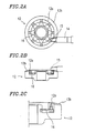
- Figures 2A to 2C are views illustrating a first example of an hypoid gear structure with some aspects of the invention, where Figure 2A is a plan view, Figure 2B is a sectional view, and Figure 2C is an enlarged partial sectional view of a main portion of the hypoid gear structure.
- Figure 3 is a view illustrating a second example of an hypoid gear structure.
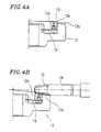
- Figures 4A and 4B are views, illustrating an example of the hypoid gear structure according to the invention, where Figure 4A is a partial sectional view of a main portion of a hypoid ring gear, and Figure 4B is a partial sectional view of a main portion of the hypoid gear structure.
- Figures 5A to 5D are views illustrating an other example of an hypoid gear structure, where Figure 5A is a plan view of a plate spring, Figure 5B is a plan view of a hypoid ring gear, Figure 5C is a sectional view of the hypoid ring gear, and Figure 5D is an enlarged partial sectional view of a main portion of the hypoid ring gear.
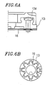
- Figures 6A and 6B are views illustrating an other example of the hypoid gear structure, where Figure 6A is a partial plan view of a main portion of a hypoid ring gear, and Figure 6B is a bottom view of the hypoid ring gear.
- Figures 7A and 7B are view illustrating an example of an hypoid gear structure not forming part of the invention, where Figure 7A is a sectional view of a main portion of a hypoid ring gear, and Figure 7B is a sectional view of a main portion of an other hypoid ring gear.
- Figures 8A and 8B are views illustrating the tooth contact of the hypoid gear structure of the second example, where Figure 8A illustrates the tooth contact of an outer ring gear and an inner ring gear, and Figure 8B illustrates the tooth contact of the inner ring gear.
- Figures 9A and 9B are views illustrating the tooth contact of an alternative hypoid gear structure of the second example, where Figure 9A illustrates the tooth contact of an outer ring gear and an inner ring gear, and Figure 9B illustrates the tooth contact of the inner ring gear.
- Figure 1 illustrates a motor-driven power steering device including a hypoid gear structure according to the present invention.
- a motor-driven power steering device 2 includes a steering shaft 7 and a rack axis 3 .
- the rotation of the steering shaft 7 is converted into a movement in the axial direction of the rack axis 3 via the engagement between a pinion gear 4 disposed coaxially with the steering shaft 7 and the rack axis 3 .
- Wheels (not shown) are coupled with both ends of the rack axis 3 via a shaft coupling (not shown) and a tie-rod (not shown). The wheels are steered rightward and leftward as the rack axis 3 moves in the axial direction.
- the steering shaft 7 includes an input axis 8 coupled with the side of a steering wheel (not shown) and an output axis 9 coupled with the side of the wheels (not shown).
- a hypoid ring gear 12 is disposed coaxially with the output axis 9 , and engages with a hypoid pinion gear 15 provided with a rotation axis 14 of an electric motor 13 .
- Figures 2A to 2C illustrate a first example of an hypoid gear structure
- Figures 2A and 2B are a plan view and a sectional view, respectively, of the hypoid gear structure
- Figure 2C is an enlarged partial sectional view of a main portion of the hypoid gear structure.
- the hypoid ring gear 12 includes an inner ring gear 12a on the inner side and an outer ring gear 12b on the outer side.
- the inner ring gear 12a is disposed on the inner periphery of the outer ring gear 12b with a plate spring 16 .
- the inner ring gear 12a is disposed so that the tooth flank thereof somewhat projects from the tooth flank of the outer ring gear 12b before the hypoid ring gear 12 and the hypoid pinion gear 15 are meshed, as shown in Figure 2C .
- the vibration energy is absorbed by bending the plate spring 16 via the inner ring gear 12a .
- the inner ring gear 12a may be made of a resin, a copper alloy, or a steel, depending on the usage of the hypoid gear structure.
- Figure 3 illustrates a second example of an hypoid gear structure .
- the inner ring gear 12a In the engagement with the hypoid pinion gear 15 , when the inner ring gear 12a is pressed down and the plate spring 16 is bent, the inner ring gear 12a is in a slanted state in the portion thereof engaging with the hypoid pinion gear 15 . That is, the axial angle of the inner ring gear 12a shifts by an angle ⁇ .
- the tooth cutting process of the inner ring gear 12a is performed by shifting the axial angle of the inner ring gear 12a by the angle a so that the tooth flank of the inner ring gear 12a and the tooth flank of the outer ring gear 12b form a continuous tooth flank when the hypoid ring gear 12 engages with the hypoid pinion gear 15 with this shifted axial angle.
- the thus-processed inner ring gear 12a and the outer ring gear 12b constitute one hypoid ring gear having a shape of continuous teeth in the state where the plate spring 16 is bent. That is, the tooth bottom and the tooth crest of the inner ring gear 12a continue with the tooth bottom and the tooth crest of the outer ring gear 12b , respectively, in the state where the plate spring 16 is bent.
- the inner ring gear 12a engages with the hypoid pinion gear 15 in the state where the tooth flank of the inner ring gear 12a is aligned with the tooth flank of the outer ring gear 12b . This ensures the transmission of the rotation.
- Figures 8A and 8B are views for illustrating the tooth contact of the second example of the hypoid gear structure according to the present invention: Figure 8A illustrates the tooth contact of the inner ring gear 12a and the outer ring gear 12b , while, Figure 8B illustrates the tooth contact of the inner ring gear 12a .
- the spring-urged inner ring gear 12a and the outer ring gear 12b correspond to ones which are obtained by dividing an integrated hypoid gear into an inner portion and an outer portion.
- the inner ring gear 12a and the outer ring gear 12b provide the same tooth contact state as that provided by the integrated hypoid gear.
- the outer ring gear 12b is in contact with the hypoid pinion gear 15 at a contact portion 21 .
- the portion other than the contact portion 21 is crowned, and is not in contact with the hypoid pinion gear 15 .
- the inner ring gear 12a which is located farther from the contact portion 21 has a large grinding undercut due to the crowing.
- Figures 9A and 9B are views for illustrating the tooth contact of an alternative hypoid gear structure of the second example according to the present invention:
- Figure 9A illustrates the tooth contact of the inner ring gear 12a and the outer ring gear 12b
- Figure 9B illustrates the tooth contact of the inner ring gear 12a .
- the contact portion 22 described above with reference to Figures 8A and 8B is formed by spring-urging the inner ring gear 12a to engage with the hypoid pinion gear 15 . This is not a contact portion formed by correct tooth contact.
- an inner ring gear 12g having a shape shown by the one-dot dash line in Figure 9A may be produced by minutely adjusting the twist angle and the pressure angle in the tooth cutting process.
- the inner ring gear 12g with this shape can form a contact portion 22a which realizes correct tooth contact with the hypoid pinion gear 15 , as shown in Figures 9A and 9B .
- an outer ring gear 12h having a shape shown by the one-dot dash line in Figure 9A the contact portion is shifted closer to the outer circumference (farther from the inner ring gear) so that the rotational force is mainly transmitted by the outer ring gear.
- the shifting of the contact portion of the outer ring gear closer to the outer circumference by changing the shape of the outer ring gear as shown by the one-dot dash line as described above is performed for the purpose of transmitting the rotational force mainly by the outer ring gear. Accordingly, this is applicable to the entirety of the second example of the hypoid gear structure.
- the inner ring gear 12g is shaped so as to be in the correct engagement with the hypoid pinion gear 15 in the state where the plate spring 16 is bent. Accordingly, the engagement of the inner ring gear 12g with the hypoid pinion gear 15 when the inner ring gear 12g is slanted is in a correct engagement state. This further ensures the transmission of the rotation.
- Figures 4A and 4B illustrate an example of the hypoid gear structure according to the present invention:
- Figure 4A is a partial sectional view of a main portion of the hypoid ring gear, and
- Figure 4B is a partial sectional view of a main portion of the hypoid gear structure.
- the inner ring gear 12a is slanted when the hypoid ring gear 12 and the hypoid pinion gear 15 engage with each other.
- a clearance 12e is provided between the outer periphery of the inner ring gear 12a and the inner periphery of the outer ring gear 12b .
- the inner ring gear 12a has a round outer periphery 12f so that the clearance 12e remains when the inner ring gear 12a is pressed down and slanted.
- the inner ring gear 12a has the outer periphery which is kept apart from the inner periphery of the outer ring gear 12b . This allows the inner ring gear 12a to be spring-urged to press the hypoid pinion gear 15 without interfering with the outer ring gear 12b . As a result, the inner ring gear 12a and the outer ring gear 12b will not interfere with each other when the plate spring 16 is bent.
- Figures 5A to 5D illustrates an other example of an hypoid gear structure :
- Figure 5A is a plan view of the spring plate 16
- Figures 5B and 5C are a plan view and a sectional view, respectively, of the hypoid ring gear
- Figure 5D is a partial sectional view of a main portion of the hypoid ring gear.
- the plate spring 16 includes a ring portion 16b and arms 16c extending in the radial direction.
- the arms 16c are bent.
- the plate spring 16 is fixed to the hypoid ring gear 12 by a fit-in ring 17 which is fitted around an axis 12c of the hypoid ring gear 12 by pressure, and held in position by the friction with the fit-in ring 17 .
- Notches 16a are formed at the inner circumference of the plate spring 16 .
- the fit-in ring 17 plastically deforms due to the notches 16a of the plate spring 16 . This provides the effect of preventing the plate spring 16 from rotating.
- the notches 16a are formed at the inner circumference of the plate spring 16 to regulate the rotation of the plate spring 16 relative to the hypoid ring gear 12 as described above. Accordingly, the inner ring gear 12a which is coupled with the body of the hypoid ring gear 12 via the plate spring 16 is kept stable relative to the body of the hypoid ring gear 12 . This allows the fixing structure of the plate spring 16 to be simplified.
- Figures 6A and 6B illustrate an other example of the hypoid gear structure according to the present invention:
- Figure 6A is a partial sectional view of a main portion of the hypoid ring gear, and
- Figure 6B is a bottom view of the hypoid ring gear.
- the plate spring 16 is fixed to a ring-shaped steel pedestal 12i with a rivet or a screw, and a resin gear 12d is formed on the pedestal 12i by insert molding.
- the inner ring gear is composed of the resin gear 12d which is formed on the pedestal 12i disposed on the spring plate 16 by insert molding. This allows for the molding of the resin gear having the plate spring. By using the gear made of a resin, the abnormal-sound reduction effect further improves.
- hypoid gear structure where the inner ring gear on the inner side of the hypoid ring gear is spring-urged to press the hypoid pinion gear has been described.
- the present invention is not limited to this construction, but the same effect as that described above can also be obtained by a hypoid gear structure where the outer ring gear on the outer side of the hypoid ring gear is spring-urged to press the hypoid pinion gear.
- Figures 7A and 7B illustrate an example of an hypoid gear structure not forming part of the present invention:
- Figure 7A is a partial sectional view of a main portion of a hypoid ring gear, and
- Figure 7B is a partial sectional view of a main portion of another hypoid ring gear.
- a hypoid ring gear 112 has a concave portion 112a which is filled with a vibration-absorbing material.
- a resin or rubber, for example, is used as the vibration-absorbing material. This reduces noise from gears, an abnormal sound such as a tooth striking sound due to backlash, and the like.
- a hypoid ring gear 212 includes concave portions 212a which are filled with a vibration-absorbing material, formed alternately in the axial direction.
- a resin or rubber, for example, is used as the vibration-absorbing material. Rubber should desirably have a large attenuation.
- the hypoid ring gear includes the first toothed portion on the inner side and the second toothed portion on the outer side. Either one of the first and second toothed portions is spring-urged to press the hypoid pinion gear.
- hypoid gear structure receives a vibration from the side of the tires (from the road surface)
- a vibration energy is absorbed by one of the first and second toothed portions which is spring-urged to press the hypoid pinion gear.
Landscapes
- Engineering & Computer Science (AREA)
- General Engineering & Computer Science (AREA)
- Mechanical Engineering (AREA)
- Chemical & Material Sciences (AREA)
- Combustion & Propulsion (AREA)
- Transportation (AREA)
- Gear Transmission (AREA)
- Power Steering Mechanism (AREA)
- Gears, Cams (AREA)
- Connection Of Motors, Electrical Generators, Mechanical Devices, And The Like (AREA)
Claims (9)
- Hypoidgetriebeaufbau mit:einem koaxial zu einer Drehachse angeordneten Hypoidzahnkranz (12); undeinem mit einer Drehachse eines Elektromotors versehenen und mit dem Hypoidzahnkranz (12) im Eingriff stehenden Hypoidritzel (15); dadurch gekennzeichnet, dassder Hypoidzahnkranz (12) einen ersten gezahnten Abschnitt (12a), der an der Innenseite angeordnet ist, sowie einen zweiten gezahnten Abschnitt (12b), der an der Aussenseite angeordnet ist, einschliesst,ein Aussenrand (12f) des ersten gezahnten Abschnitts (12a) so geformt ist, dass er von einem Innenrand des zweiten gezahnten Abschnitts (12b) beabstandet gehalten wird,der erste gezahnte Abschnitt (12a) durch eine Feder (16) gegen das Hypoidritzel (15) gedrückt wird undder erste gezahnte Abschnitt (12a) über die Feder (16) an den zweiten gezahnten Abschnitt (12b) angekoppelt ist, wobei es die Feder (16) dem ersten gezahnten Abschnitt (12a) gestattet, sich bezüglich des zweiten gezahnten Abschnitts (12b) schräg zu stellen, wenn der erste gezahnte Abschnitt mit dem Ritzel (15) in Eingriff kommt.
- Hypoidgetriebeaufbau gemäss Anspruch 1, worin der erste gezahnte Abschnitt (12a) so geformt ist, dass er sich in einem Zustand, in dem der erste gezahnte Abschnitt (12a) mit dem Hypoidritzel (15) in Eingriff kommt und die Feder (16) gespannt ist, mit dem Hypoidritzel in korrektem Eingriff befindet.
- Hypoidgetriebeaufbau gemäss Anspruch 1, worin die Feder eine Tellerfeder (16) mit einem Ringabschnitt ist, und
ein drehungsregulierender Abschnitt (17) zur Regelung der Drehung der Tellerfeder bezüglich des zweiten gezahnten Abschnitts an einem Innenrand der Tellerfeder (16) ausgebildet ist. - Hypoidgetriebeaufbau gemäss Anspruch 1, worin der erste gezahnte Abschnitt (12a) aus einem Kunstharz besteht.
- Hypoidgetriebeaufbau gemäss Anspruch 4, worin der erste gezahnte Abschnitt (12a) auf einem Sockel ausgebildet ist, der durch Insert Molding auf der Feder (16) angeordnet wurde.
- Hypoidgetriebeaufbau gemäss Anspruch 1, worin die Zahnflanke des ersten gezahnten Abschnitts (12a) und die Zahnflanke des zweiten gezahnten Abschnitts (12b) in dem Zustand eine durchgehende Zahnflanke bilden, in dem der erste gezahnte Abschnitt (12a) mit dem Hypoidritzel (15) in Eingriff kommt und die Feder (16) gespannt ist.
- Hypoidgetriebeaufbau gemäss Anspruch 1, in dem der Hypoidzahnkranz einen konkaven Abschnitt (112a, 212a) einschliesst und der konkave Abschnitt mit einem vibrationsabsorbierenden Material gefüllt ist.
- Hypoidgetriebeaufbau gemäss Anspruch 1, in dem der Hypoidzahnkranz konkave Abschnitte (212a) einschliesst, die abwechselnd in einer vorbestimmten Richtung ausgebildet sind.
- Hypoidgetriebeaufbau gemäss Anspruch 8, in dem die konkaven Abschnitte (212a) mit einem vibrationsabsorbierenden Material gefüllt sind.
Applications Claiming Priority (6)
| Application Number | Priority Date | Filing Date | Title |
|---|---|---|---|
| JP279241/97 | 1997-10-13 | ||
| JP27924197 | 1997-10-13 | ||
| JP27924197 | 1997-10-13 | ||
| JP33914197A JP3562948B2 (ja) | 1997-10-13 | 1997-12-09 | ハイポイドギヤ構造 |
| JP339141/97 | 1997-12-09 | ||
| JP33914197 | 1997-12-09 |
Publications (3)
| Publication Number | Publication Date |
|---|---|
| EP0908647A2 EP0908647A2 (de) | 1999-04-14 |
| EP0908647A3 EP0908647A3 (de) | 2000-05-17 |
| EP0908647B1 true EP0908647B1 (de) | 2003-04-23 |
Family
ID=26553229
Family Applications (1)
| Application Number | Title | Priority Date | Filing Date |
|---|---|---|---|
| EP98119236A Expired - Lifetime EP0908647B1 (de) | 1997-10-13 | 1998-10-12 | Aufbau eines Hypoidgetriebes |
Country Status (4)
| Country | Link |
|---|---|
| US (2) | US6170349B1 (de) |
| EP (1) | EP0908647B1 (de) |
| JP (1) | JP3562948B2 (de) |
| DE (1) | DE69813717T2 (de) |
Families Citing this family (18)
| Publication number | Priority date | Publication date | Assignee | Title |
|---|---|---|---|---|
| GB9822603D0 (en) * | 1998-10-17 | 1998-12-09 | Trw Lucas Varity Electric | Improvements relating to electric power steering systems |
| JP3631084B2 (ja) | 1999-09-13 | 2005-03-23 | 光洋精工株式会社 | 塗装品およびその製造方法および塗装装置 |
| JP2001159451A (ja) | 1999-11-30 | 2001-06-12 | Toyota Motor Corp | 傘状歯車機構 |
| DE10000219A1 (de) * | 2000-01-05 | 2001-07-12 | Bosch Gmbh Robert | Stellglied für eine Fahrzeug-Lenkvorrichtung |
| US7595095B2 (en) | 2000-09-12 | 2009-09-29 | Koyo Seiko Co. | Coated article, manufacturing method therefor and coating apparatus |
| US6378647B1 (en) * | 2000-09-26 | 2002-04-30 | Delphi Technologies, Inc. | Electric power steering assist mechanism with isolated output shaft |
| JP3765232B2 (ja) * | 2000-11-16 | 2006-04-12 | 株式会社ジェイテクト | 電動式パワーステアリング装置及びこれに用いる歯車の製造方法 |
| US20020078777A1 (en) * | 2000-12-27 | 2002-06-27 | Witucki David E. | Gear assembly |
| JP2004340367A (ja) * | 2003-04-25 | 2004-12-02 | Thk Co Ltd | ハイポイドギア装置 |
| US7672444B2 (en) * | 2003-12-24 | 2010-03-02 | At&T Intellectual Property, I, L.P. | Client survey systems and methods using caller identification information |
| US7195095B2 (en) * | 2004-02-27 | 2007-03-27 | General Motors Corporation | Floating PRNDL face plate assembly and method to accommodate floor build variations |
| JP4516431B2 (ja) * | 2004-04-26 | 2010-08-04 | 本田技研工業株式会社 | ウォームギヤ機構及びウォームギヤ機構を搭載した電動パワーステアリング装置 |
| JP4515834B2 (ja) * | 2004-06-22 | 2010-08-04 | 株式会社ジェイテクト | 電動パワーステアリング装置 |
| US20060123942A1 (en) * | 2004-12-14 | 2006-06-15 | Facciolla Arthur O | Constructive arrangement in metallic gear |
| CN103085066B (zh) * | 2006-04-21 | 2015-09-09 | Abb公司 | 工业机器人的锥齿轮装置、臂的腕部和调整侧隙的方法 |
| AT510575B1 (de) * | 2010-09-24 | 2012-05-15 | Miba Sinter Austria Gmbh | Zahnrad |
| JP7244565B2 (ja) * | 2021-03-29 | 2023-03-22 | 株式会社ソニー・インタラクティブエンタテインメント | 関節ユニット |
| JP7342055B2 (ja) * | 2021-03-29 | 2023-09-11 | 株式会社ソニー・インタラクティブエンタテインメント | 関節ユニット |
Family Cites Families (12)
| Publication number | Priority date | Publication date | Assignee | Title |
|---|---|---|---|---|
| US4328879A (en) * | 1978-04-27 | 1982-05-11 | The Gates Rubber Company | Shock-absorbing sprocket, drive assembly, and the like |
| US4719813A (en) * | 1983-10-28 | 1988-01-19 | Lazar Chalik | Gear assembly |
| JPH02127842U (de) | 1989-03-28 | 1990-10-22 | ||
| JPH03122978U (de) * | 1990-03-28 | 1991-12-13 | ||
| US5182960A (en) | 1991-12-10 | 1993-02-02 | Allied-Signal Inc. | Bevel gear drive arrangement |
| US5257543A (en) * | 1992-09-03 | 1993-11-02 | Borg-Warner Automotive, Inc. | Gear transmission with an anti-rattle system |
| JPH06200987A (ja) | 1992-12-28 | 1994-07-19 | Kayaba Ind Co Ltd | ハイポイド歯車伝達装置 |
| JPH07232653A (ja) | 1994-02-22 | 1995-09-05 | Nippon Seiko Kk | 電動式パワーステアリング装置 |
| JPH07232651A (ja) | 1994-02-22 | 1995-09-05 | Nippon Seiko Kk | 電動式パワーステアリング装置 |
| JPH08177984A (ja) * | 1994-12-28 | 1996-07-12 | Fanuc Ltd | バックラッシを調整可能に構成した歯車装置 |
| US5813335A (en) * | 1996-12-18 | 1998-09-29 | Heidelberg Harris Inc. | Apparatus for preventing backlash between the meshing teeth of a first and a second gear in a printing unit of a lithographic rotary printing press |
| US5870928A (en) * | 1997-05-08 | 1999-02-16 | Cummins Engine Company, Inc. | Anti-lash gear with alignment device |
-
1997
- 1997-12-09 JP JP33914197A patent/JP3562948B2/ja not_active Expired - Fee Related
-
1998
- 1998-10-09 US US09/168,942 patent/US6170349B1/en not_active Expired - Lifetime
- 1998-10-12 EP EP98119236A patent/EP0908647B1/de not_active Expired - Lifetime
- 1998-10-12 DE DE69813717T patent/DE69813717T2/de not_active Expired - Lifetime
-
2000
- 2000-11-02 US US09/703,843 patent/US6339967B1/en not_active Expired - Lifetime
Also Published As
| Publication number | Publication date |
|---|---|
| EP0908647A2 (de) | 1999-04-14 |
| DE69813717D1 (de) | 2003-05-28 |
| JP3562948B2 (ja) | 2004-09-08 |
| EP0908647A3 (de) | 2000-05-17 |
| US6339967B1 (en) | 2002-01-22 |
| DE69813717T2 (de) | 2004-02-26 |
| US6170349B1 (en) | 2001-01-09 |
| JPH11182636A (ja) | 1999-07-06 |
Similar Documents
| Publication | Publication Date | Title |
|---|---|---|
| US6339967B1 (en) | Vibration dampening hypoid gear structure | |
| EP1452419B1 (de) | Elektrische servolenkvorrichtung | |
| US6629578B2 (en) | Electric power steering system | |
| JP3909908B2 (ja) | 動力伝達装置 | |
| EP1468897A2 (de) | Schneckenmechanismus und elektrische Servolenkung ausgestattet mit einem Schneckenmechanismus | |
| US20040182188A1 (en) | Motor-driven type power steering apparatus | |
| JP5176577B2 (ja) | 電動パワーステアリング装置 | |
| US20050066769A1 (en) | Wave gear device | |
| US20040221668A1 (en) | Electric power steering apparatus | |
| JP4013132B2 (ja) | 電動パワーステアリング装置 | |
| US6976556B2 (en) | Electric power steering apparatus | |
| JP2007247734A (ja) | ウォーム式減速機及び電動式パワーステアリング装置 | |
| JP2001132823A (ja) | 歯車装置 | |
| US20090042655A1 (en) | Power transmission device and method of producing the same | |
| JPH09250604A (ja) | ウォームギヤ付モータ | |
| KR100235177B1 (ko) | 가용성 축 조인트 | |
| JP2001132822A (ja) | 歯車装置 | |
| JP2006349091A (ja) | ハーモニックドライブ装置、伝達比可変装置、及び車両用操舵装置 | |
| JP2001165246A (ja) | 歯車減速装置 | |
| JP4882906B2 (ja) | 電動式パワーステアリング装置 | |
| JP2004211789A (ja) | 撓み軸継ぎ手 | |
| JP3898548B2 (ja) | 車両のステアリング装置 | |
| EP1121287A1 (de) | Verbesserungen in verbindung mit elektrischen servolenkungen | |
| JP3681912B2 (ja) | 電動パワーステアリング装置 | |
| KR20250022484A (ko) | 전동식 스티어링 파워장치 |
Legal Events
| Date | Code | Title | Description |
|---|---|---|---|
| PUAI | Public reference made under article 153(3) epc to a published international application that has entered the european phase |
Free format text: ORIGINAL CODE: 0009012 |
|
| 17P | Request for examination filed |
Effective date: 19981028 |
|
| AK | Designated contracting states |
Kind code of ref document: A2 Designated state(s): DE FR GB |
|
| AX | Request for extension of the european patent |
Free format text: AL;LT;LV;MK;RO;SI |
|
| K1C1 | Correction of patent application (title page) published |
Effective date: 19990414 |
|
| RAP1 | Party data changed (applicant data changed or rights of an application transferred) |
Owner name: NISSEI INDUSTRIES LTD. Owner name: TOYOTA JIDOSHA KABUSHIKI KAISHA |
|
| PUAL | Search report despatched |
Free format text: ORIGINAL CODE: 0009013 |
|
| AK | Designated contracting states |
Kind code of ref document: A3 Designated state(s): AT BE CH CY DE DK ES FI FR GB GR IE IT LI LU MC NL PT SE |
|
| AX | Request for extension of the european patent |
Free format text: AL;LT;LV;MK;RO;SI |
|
| AKX | Designation fees paid |
Free format text: DE FR GB |
|
| 17Q | First examination report despatched |
Effective date: 20020318 |
|
| GRAH | Despatch of communication of intention to grant a patent |
Free format text: ORIGINAL CODE: EPIDOS IGRA |
|
| GRAH | Despatch of communication of intention to grant a patent |
Free format text: ORIGINAL CODE: EPIDOS IGRA |
|
| GRAA | (expected) grant |
Free format text: ORIGINAL CODE: 0009210 |
|
| AK | Designated contracting states |
Designated state(s): DE FR GB |
|
| REG | Reference to a national code |
Ref country code: GB Ref legal event code: FG4D |
|
| REF | Corresponds to: |
Ref document number: 69813717 Country of ref document: DE Date of ref document: 20030528 Kind code of ref document: P |
|
| ET | Fr: translation filed | ||
| PLBE | No opposition filed within time limit |
Free format text: ORIGINAL CODE: 0009261 |
|
| STAA | Information on the status of an ep patent application or granted ep patent |
Free format text: STATUS: NO OPPOSITION FILED WITHIN TIME LIMIT |
|
| 26N | No opposition filed |
Effective date: 20040126 |
|
| PGFP | Annual fee paid to national office [announced via postgrant information from national office to epo] |
Ref country code: GB Payment date: 20131009 Year of fee payment: 16 Ref country code: FR Payment date: 20131009 Year of fee payment: 16 Ref country code: DE Payment date: 20131009 Year of fee payment: 16 |
|
| REG | Reference to a national code |
Ref country code: DE Ref legal event code: R119 Ref document number: 69813717 Country of ref document: DE |
|
| GBPC | Gb: european patent ceased through non-payment of renewal fee |
Effective date: 20141012 |
|
| PG25 | Lapsed in a contracting state [announced via postgrant information from national office to epo] |
Ref country code: GB Free format text: LAPSE BECAUSE OF NON-PAYMENT OF DUE FEES Effective date: 20141012 Ref country code: DE Free format text: LAPSE BECAUSE OF NON-PAYMENT OF DUE FEES Effective date: 20150501 |
|
| REG | Reference to a national code |
Ref country code: FR Ref legal event code: ST Effective date: 20150630 |
|
| PG25 | Lapsed in a contracting state [announced via postgrant information from national office to epo] |
Ref country code: FR Free format text: LAPSE BECAUSE OF NON-PAYMENT OF DUE FEES Effective date: 20141031 |