EP0908705B1 - Débitmètre massique - Google Patents
Débitmètre massique Download PDFInfo
- Publication number
- EP0908705B1 EP0908705B1 EP98117064A EP98117064A EP0908705B1 EP 0908705 B1 EP0908705 B1 EP 0908705B1 EP 98117064 A EP98117064 A EP 98117064A EP 98117064 A EP98117064 A EP 98117064A EP 0908705 B1 EP0908705 B1 EP 0908705B1
- Authority
- EP
- European Patent Office
- Prior art keywords
- coriolis
- mass flow
- flow meter
- coriolis tube
- tube
- Prior art date
- Legal status (The legal status is an assumption and is not a legal conclusion. Google has not performed a legal analysis and makes no representation as to the accuracy of the status listed.)
- Expired - Lifetime
Links
Images



Classifications
-
- G—PHYSICS
- G01—MEASURING; TESTING
- G01F—MEASURING VOLUME, VOLUME FLOW, MASS FLOW OR LIQUID LEVEL; METERING BY VOLUME
- G01F1/00—Measuring the volume flow or mass flow of fluid or fluent solid material wherein the fluid passes through a meter in a continuous flow
- G01F1/76—Devices for measuring mass flow of a fluid or a fluent solid material
- G01F1/78—Direct mass flowmeters
- G01F1/80—Direct mass flowmeters operating by measuring pressure, force, momentum, or frequency of a fluid flow to which a rotational movement has been imparted
- G01F1/84—Coriolis or gyroscopic mass flowmeters
- G01F1/8409—Coriolis or gyroscopic mass flowmeters constructional details
-
- G—PHYSICS
- G01—MEASURING; TESTING
- G01F—MEASURING VOLUME, VOLUME FLOW, MASS FLOW OR LIQUID LEVEL; METERING BY VOLUME
- G01F1/00—Measuring the volume flow or mass flow of fluid or fluent solid material wherein the fluid passes through a meter in a continuous flow
- G01F1/76—Devices for measuring mass flow of a fluid or a fluent solid material
- G01F1/78—Direct mass flowmeters
- G01F1/80—Direct mass flowmeters operating by measuring pressure, force, momentum, or frequency of a fluid flow to which a rotational movement has been imparted
- G01F1/84—Coriolis or gyroscopic mass flowmeters
- G01F1/8409—Coriolis or gyroscopic mass flowmeters constructional details
- G01F1/8413—Coriolis or gyroscopic mass flowmeters constructional details means for influencing the flowmeter's motional or vibrational behaviour, e.g., conduit support or fixing means, or conduit attachments
-
- G—PHYSICS
- G01—MEASURING; TESTING
- G01F—MEASURING VOLUME, VOLUME FLOW, MASS FLOW OR LIQUID LEVEL; METERING BY VOLUME
- G01F1/00—Measuring the volume flow or mass flow of fluid or fluent solid material wherein the fluid passes through a meter in a continuous flow
- G01F1/76—Devices for measuring mass flow of a fluid or a fluent solid material
- G01F1/78—Direct mass flowmeters
- G01F1/80—Direct mass flowmeters operating by measuring pressure, force, momentum, or frequency of a fluid flow to which a rotational movement has been imparted
- G01F1/84—Coriolis or gyroscopic mass flowmeters
- G01F1/8409—Coriolis or gyroscopic mass flowmeters constructional details
- G01F1/8413—Coriolis or gyroscopic mass flowmeters constructional details means for influencing the flowmeter's motional or vibrational behaviour, e.g., conduit support or fixing means, or conduit attachments
- G01F1/8418—Coriolis or gyroscopic mass flowmeters constructional details means for influencing the flowmeter's motional or vibrational behaviour, e.g., conduit support or fixing means, or conduit attachments motion or vibration balancing means
-
- G—PHYSICS
- G01—MEASURING; TESTING
- G01F—MEASURING VOLUME, VOLUME FLOW, MASS FLOW OR LIQUID LEVEL; METERING BY VOLUME
- G01F1/00—Measuring the volume flow or mass flow of fluid or fluent solid material wherein the fluid passes through a meter in a continuous flow
- G01F1/76—Devices for measuring mass flow of a fluid or a fluent solid material
- G01F1/78—Direct mass flowmeters
- G01F1/80—Direct mass flowmeters operating by measuring pressure, force, momentum, or frequency of a fluid flow to which a rotational movement has been imparted
- G01F1/84—Coriolis or gyroscopic mass flowmeters
- G01F1/845—Coriolis or gyroscopic mass flowmeters arrangements of measuring means, e.g., of measuring conduits
- G01F1/8468—Coriolis or gyroscopic mass flowmeters arrangements of measuring means, e.g., of measuring conduits vibrating measuring conduits
-
- G—PHYSICS
- G01—MEASURING; TESTING
- G01F—MEASURING VOLUME, VOLUME FLOW, MASS FLOW OR LIQUID LEVEL; METERING BY VOLUME
- G01F1/00—Measuring the volume flow or mass flow of fluid or fluent solid material wherein the fluid passes through a meter in a continuous flow
- G01F1/76—Devices for measuring mass flow of a fluid or a fluent solid material
- G01F1/78—Direct mass flowmeters
- G01F1/80—Direct mass flowmeters operating by measuring pressure, force, momentum, or frequency of a fluid flow to which a rotational movement has been imparted
- G01F1/84—Coriolis or gyroscopic mass flowmeters
- G01F1/845—Coriolis or gyroscopic mass flowmeters arrangements of measuring means, e.g., of measuring conduits
- G01F1/8468—Coriolis or gyroscopic mass flowmeters arrangements of measuring means, e.g., of measuring conduits vibrating measuring conduits
- G01F1/849—Coriolis or gyroscopic mass flowmeters arrangements of measuring means, e.g., of measuring conduits vibrating measuring conduits having straight measuring conduits
Definitions
- the invention relates to a mass flow meter based on the Coriolis principle essentially works with a flowing medium straight Coriolis line, with at least one assigned to the Coriolis line, the Coriolis line stimulating vibration generator, with at least one assigned to the Coriolis line, Coriolis forces and / or Coriolis vibrations-based transducers and with a receiving cylinder receiving the Coriolis line.
- a mass flow meter is known from EP 0 415 129 A2
- the mass flow meter in question u. a. belong at least one "assigned" to the Coriolis line Vibration generator and at least one "assigned" to the Coriolis line Transducer.
- the vibrator or the Vibration generator at least a part of the vibration generator or a Part of the vibration generator and the sensor or the sensor, in any case part of the transducer or part of the Sensor connected to the Coriolis line.
- the expression "assigned" - instead of the expression "connected" - has been used.
- mass flow meters that work on the Coriolis principle, differentiates one basically between those whose Coriolis line is at least essentially straight, and on the other hand those whose Coriolis line is loop-shaped. Moreover a distinction is made between the mass flow meters in question between those on the one hand that have only one Coriolis line and the other those that have two Coriolis lines; in the embodiments with two Coriolis lines, these can be fluidically connected Row or parallel to each other.
- mass flow meters have become increasingly popular only one essentially straight Coriolis line.
- mass flow with a straight Coriolis line are in terms of mechanical Easy to set up, d. H. can be produced at comparatively low costs, well machinable on the inner surfaces of the Coriolis line, e.g. B. polishable, have a low pressure drop and are self-draining.
- Mass flow meters with only a straight Coriolis line are despite all advantages problematic from a number of points of view.
- mass flow meters with only one Coriolis line the coupling of external disturbances more than with mass flow meters, where two parallel Coriolis lines follow kind of a tuning fork operated because of mass flow meters with only one Coriolis line the center of mass of the mass flow meter not resting.
- DE 197 32 605 A1 deals with the difficulty encountered in mass flow meters with a straight Coriolis line when measuring the extremely small phase difference in these mass flow meters between two measurement signals supplied by the sensors, which are proportional to the mass flow.
- the common requirements in industry for the measuring accuracy of mass flow meters require a resolution of the phase difference in the order of 1 ⁇ 10 -5 degrees.
- EP 0 415 129 A2 describes a Coriolis mass flow meter described, essentially from a measuring line in the form of a thick-walled, straight tube that exists on his both ends with two flexible connectors with the further pipeline connected is. Due to the two flexible connectors is one slight vibration of the measuring line around a swivel axis possible. The ends follow when the pipe is pivoted about the pivot axis of the tube of a linear movement, alternately up and down.
- the measurement method in the device known from EP 0 415 129 A2 is based now that the Coriolis effect to generate such a vibration of the pipe is used, which is the externally excited pivoting superimposed, with the pivot axis of the tube based on the length of the tube is arranged off-center.
- the Coriolis forces generated act here in the same plane in which the pipe is pivoted, so that it remains with such movement of the ends of the tubes, that runs along a straight line.
- WO 95/16897 describes a Coriolis mass flow meter, in which the Coriolis line is excited in a radial oscillation mode becomes. Thereby, Coriolis forces run along the wall of the Coriolis line generated, which leads to a deformation of the cross-sectional shape of the Coriolis line lead depending on the mass flow.
- EP 0 578 113 A2 describes a Coriolis mass flow meter with a Changes in the vibration length of the Coriolis line Length change sensor for vibration length and voltage dependent Correction of the measured value known.
- EP 0 261 435 A2 describes a Coriolis mass flow meter described that a mechanical vibration system with two straight measuring tubes has that are clamped at both ends.
- the mechanical The vibrating system is arranged axially in a carrier tube.
- a vibration exciter is arranged, the two measuring tubes in opposite phase bending vibrations offset.
- a correction circuit receives that from the two temperature sensors generated temperature sensor signals and issued based on the measurement signal a correction to eliminate the influence of temperature on the measured temperatures on the measurement result.
- EP 0 317 340 A2 describes a Coriolis mass flow meter, which has a Coriolis line that over two cylindrical bellows an outer housing is connected.
- the bellows absorb the thermal expansion the Coriolis line and the outer pipe system and protect the Coriolis line also in front from the outer pipe system into the Coriolis line coupling vibrations.
- EP 0 469 448 A1 describes such a Coriolis mass flow meter described that a relative at a certain length low natural frequency or a relative at a certain natural frequency has a small overall length, namely in that the vibration generator attacks via a pendulum arm on the Coriolis line, so that the Coriolis line stimulated to torsional vibrations and bending vibrations becomes.
- the invention has for its object to provide a mass flow meter, in the case of at least constant measuring accuracy and constant thickness of the Coriolis line the length of the Coriolis line can be further reduced, while ensuring that thermal Expansion or tension of the Coriolis line not too mechanical Damage to the mass flow meter.
- the above-mentioned object is achieved in that the Coriolis line via an inlet and an outlet in the receiving cylinder is movable in the axial and radial directions, the ends of the Coriolis conduction from the vibrators to themselves transversal Movements of the ends of the Coriolis line composing, rotary tumbling movements around the longitudinal axis of the Coriolis line can be stimulated are and the rotational tumbling movements of one end the Coriolis line is 180 ° out of phase with the rotary line are wobbling movements of the other end of the Coriolis line.
- the Coriolis line is deformed, as in the known one Mass flow meter, from which the invention is based, not required; also a "practically limitless" rigid Coriolis line of an inventive Coriolis mass flow meter can be excited that in connection with a medium flowing in the Coriolis line Coriolis forces are generated.
- a deformity of the Coriolis line is not required, the Coriolis line, based on its nominal size, run with short length, so that then the total length of the mass flow meter according to the invention can be relatively low, in particular then, if the inlet and the outlet are of short length exhibit.
- the receiving cylinder and the components used to store the Coriolis line can z. B. realize a mass flow meter that at a maximum mass flow of 300 kg / min only a total length of 20 cm to a maximum of 30 cm.
- a particularly preferred embodiment of the mass flow meter according to the invention is characterized in that the receiving cylinder forms the meter housing of the mass flow meter, preferably the receiving cylinder as a - relatively heavy - metal block Recesses for the reception of Coriolis line, vibration generator and transducer is formed.
- This embodiment of an inventive Mass flow meter can easily between the Flanges of adjacent pipelines must be pinched, whereby - of course in Limits - a non-alignment of the Coriolis line with the adjacent ones Piping does not cause problems.
- the mass flow meter according to the invention can also, as in State of the art actually common, in addition to the receiving cylinder have special measuring device housing, which is then expediently on both sides Has flanges.
- the Coriolis line and the measuring device housing two connecting lines are provided.
- the connecting lines to the inlet and the Outlet - approximately in the middle of the extension - connected.
- the wanted - "limitless" mobility of the Coriolis line is useful if the previously mentioned connecting lines formed as membranes are.
- mass flow meters according to the invention must be implemented of the measures that lead to the required vibrations of the Coriolis line lead, of course, also take into account that the Coriolis line movable in the receiving cylinder in the axial and radial directions is stored. Not all of the generation measures known in the prior art of vibrations of the Coriolis line are also in the invention Mass flow meter applicable.
- the z. B. by changing temperatures of the flowing medium are generated, if possible
- at least the Coriolis line from a material with a there is relatively little thermal expansion can in particular duplex, stainless steel, nickel, titanium or carbon or glass fiber reinforced Material can be used.
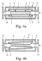
- the mass flowmeters shown in FIGS. 1 to 4 and in FIGS. 10 to 12 work, as is known, according to the Coriolis principle and consist in their basic structure of a flowing Coriolis line 1, one of the Coriolis line 1 assigned to the Coriolis line 1 stimulating vibration generator 2 (FIGS. 1 and 2) or from two of the Coriolis line 1 assigned to the Coriolis line 1 exciting vibration generators 2, 3 (FIGS. 3 and 4 and 10 to 12), from two Coriolis lines 1, Coriolis forces and / or Coriolis vibrations based measurement sensors 4, 5 and from a Coriolis line 1 receiving cylinder 6.
- the Coriolis line 1 via a conically widening inlet 7 and also one flared outlet 8 floating in the receiving cylinder 6 stored.
- This floating bearing causes the Coriolis line to deform 1 not required; also a "practically limitless" rigid Coriolis cable 1, which is floating, can be excited so that in Connection with a medium Coriolis forces flowing in the Coriolis line 1 be generated.
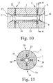
- FIGS. 10 and 11 show embodiments of Mass flow meters, which is characterized in that the receiving cylinder 6 forms the measuring device housing of the mass flow meter, the receiving cylinder 6 as a - relatively heavy - metal block Recesses for receiving Coriolis line 1, vibration generator 2 or vibration generator 2, 3 and transducer 4, 5 is formed.
- These embodiments can easily be between the - not shown - Flanges of adjacent pipes must be clamped, whereby - within limits of course - a non-alignment of the Coriolis line 1 with the adjacent ones Piping does not cause problems.
- 4 and 12 show an embodiment of a mass flow meter, which is characterized in that in addition to the receiving cylinder 6 is still a meter housing 9 and between the Coriolis line 1 and the measuring device housing 9 two connecting lines 10, 11 are provided.
- 4 shows the connecting lines 10, 11 at the conically widening inlet 7 and also conically expanding outlet 8 - connected approximately in the middle of the extension.
- the connecting lines 10, 11 are just like the inlet 7 and the outlet 8 is designed as membranes and is the measuring device housing 9 provided with flanges 12, 13.
- FIG. 12 shows an exemplary embodiment of a Mass flow meter, which is characterized in that the inlet 7 and the outlet 8 are arcuate.
- the inlet 7 and the outlet 8 can each expand slightly, without the large stresses occurring in the inlet 7 or in the outlet 8, so that also no large voltages are transmitted to the Coriolis line 1.
- the Coriolis line 1 can expand itself slightly, without the large tensions occur in it, since the inlet 7 and the outlet 8 also allow such an expansion - of course to a small extent.
- Fig. 4 a shows a mass flow meter in the static state, i.e. if there are no vibrations.
- Fig. 4 b) shows the mass flow meter with an existing excitation vibration
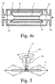
- Fig. 4 c) the mass flow meter with an existing Coriolis vibration. Both when there is an excitation vibration as well when there is a Coriolis vibration, the Coriolis line 1 swings in phase opposition to the receiving cylinder 6. Thus there is a balanced system before, with very little energy and only slight vibrations the measuring device housing 9 is transmitted.
- Mass flow meters take into account that the Coriolis line 1 is floating in the receiving cylinder 6.
- the vibration generator 2 (Fig. 1 and 2) or the vibration generator 2, 3 (FIGS. 3, 4 and 12) the Coriolis line 1 to vibrations around a transverse to the longitudinal axis of the Coriolis line 1 Excitation axis or excite, - wherein the vibration axis in the central plane running perpendicular to the longitudinal axis of the Coriolis line 1 the mass flow meter or the Coriolis line 1.
- the Coriolis line 1 thus swings symmetrically to the perpendicular to the longitudinal axis the Coriolis line 1 running center plane, but in each case out of phase by 180 °.
- the 1 shows an embodiment of a mass flow meter, in which the vibration generator 2 between the receiving cylinder 6 and one transverse to the longitudinal axis of the Coriolis line 1, essentially in the longitudinal direction in the middle of the Coriolis line 1 attached pendulum 17 attacks.
- the pendulum 17 includes a pendulum arm 18 and a compensation mass 19.
- the compensation mass 19 is chosen so that the natural frequency of the pendulum 17 as far as possible with the natural frequency of the excitation vibration Coriolis line 1 matches.
- the vibration generator 2 engages between the receiving cylinder 6 and one transverse to the longitudinal axis of the Coriolis line 1, in the longitudinal direction attached essentially in the middle of the Coriolis line 1, with a Compensation mass 20 provided torsion bar 21.
- a mass flow meter shown in Fig. 3 applies that two vibration generator 2, 3 in the longitudinal direction of the Coriolis line 1, left and right of the middle, are arranged, the Vibration generator 2, 3 as piezo elements supported on spring elements 22, 23 24, 25 are executed.
- Fig. 5 shows for the first embodiment of a mass flow meter the Coriolis line 1 and the pendulum 17 in a schematic diagram for the excitation vibration. It can easily be seen that the Coriolis line 1 vibrations about a transverse to the longitudinal axis of the Coriolis line 1 running vibration axis executes. The axis of vibration 5 is perpendicular to the plane of the drawing. 5 you can also remove that the Coriolis line 1 due to the floating storage rather, it does not experience any deformation. Practically only those in are deformed Fig. 5 indicated membranes.
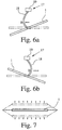
- 6 a) and 6 b) are to explain the pendulum 17 and the Coriolis line 1 attacking forces the Coriolis line 1 and the pendulum 17 shown in different phases of the excitation oscillation. there the deformations of the pendulum arm 18 are each shown greatly enlarged.
- FIG. 7 shows in principle that of the excitation oscillation shown in FIG. 5 superimposed Coriolis vibration caused by the flow of the flowing medium through the Coriolis line 1 resulting Coriolis forces is excited.
- the superposition of the Coriolis vibration shown in FIG. 7 leads to a measurable phase difference of the Vibration of two points to the right and left of the center of the Coriolis line 1. This phase difference is proportional to the mass flow, since it is the phase difference Coriolis forces causing the mass flow through the Coriolis line 1 are proportional.
Landscapes
- Physics & Mathematics (AREA)
- Fluid Mechanics (AREA)
- General Physics & Mathematics (AREA)
- Measuring Volume Flow (AREA)
Claims (13)
- Débitmètre massique fonctionnant selon le principe de Coriolis comprenant une conduite de Coriolis (1) sensiblement droite et guidant un milieu s'écoulant, comprenant des générateurs d'oscillations (2, 3) associés à la conduite de Coriolis (1) et excitant la conduite de Coriolis (1), comprenant au moins un transducteur (4, 5) associé à la conduite de Coriolis (1) et détectant des forces de Coriolis et/ou des oscillations de Coriolis reposant sur des forces de Coriolis et comprenant un cylindre de réception (6) recevant la conduite de Coriolis (1), caractérisé en ce que la conduite de Coriolis (1) est montée mobile dans la direction axiale et radiale par le biais d'une entrée (7) et par le biais d'une sortie (8) dans le cylindre de réception (6), les extrémités de la conduite de Coriolis (1) sont excitables par les générateurs d'oscillations (2, 3) en des mouvements autour de l'axe longitudinal de la conduite de Coriolis (1) se composant de mouvements transversaux des extrémités de la conduite de Coriolis en nutation rotatoire et les mouvements en nutation rotatoire d'une extrémité de la conduite de Coriolis (1) sont décalés en phase de 180° par rapport aux mouvements en nutation rotatoire de l'autre extrémité de la conduite de Coriolis (1).
- Débitmètre massique selon la revendication 1, caractérisé en ce que sont prévus en tant que générateurs d'oscillations (2, 3) des éléments générateurs d'oscillations (26) décalés à chaque fois le long du pourtour de la conduite de Coriolis (1) de 90° l'un par rapport à l'autre et générant des mouvements transversaux et les éléments générateurs d'oscillations individuels (26) sont excitables de manière sinusoïdale avec un décalage de phase de 90°.
- Débitmètre massique selon la revendication 1 ou 2, caractérisé en ce que l'entrée (7) et la sortie (8) sont réalisées à chaque fois sous forme de membrane s'élargissant de manière conique.
- Débitmètre massique selon l'une quelconque des revendications 1 à 3, caractérisé en ce que l'entrée (7) et la sortie (8) sont réalisées à chaque fois en forme d'arc de sorte que l'entrée (7) et la sortie (8) peuvent se dilater à chaque fois légèrement sans que de fortes tensions ne se produisent dans l'entrée (7), dans la sortie (8) ou dans la conduite de Coriolis (1).
- Débitmètre massique selon l'une quelconque des revendications 1 à 4, caractérisé en ce que le débitmètre massique présente un boítier d'appareil de mesure et le cylindre de réception (6) forme le boítier d'appareil de mesure du débitmètre massique.
- Débitmètre massique selon la revendication 5, caractérisé en ce que le cylindre de réception (6) est fabriqué en métal et présente des évidements en vue de la réception de la conduite de Coriolis (1), du générateur d'oscillations (2, 3) et du transducteur (4, 5).
- Débitmètre massique selon l'une quelconque des revendications 1 à 4, caractérisé en ce qu'en plus du cylindre de réception (6), un boítier d'appareil de mesure (9) est présent et la conduite de Coriolis (1) est reliée avec le boítier d'appareil de mesure (9) au moyen de deux conduites de liaison (10, 11).
- Débitmètre massique selon la revendication 7, caractérisé en ce que les conduites de liaison (10, 11) sont raccordées à l'entrée (7) et à la sortie (8).
- Débitmètre massique selon la revendication 7 ou 8, caractérisé en ce que les conduites de liaison (10, 11) sont réalisées en tant que membranes.
- Débitmètre massique selon l'une quelconque des revendications 1 à 9, caractérisé en ce que les générateurs d'oscillations (2, 3) sont réalisés en tant qu'éléments piézoélectriques (24, 25) appuyés sur des éléments élastiques (22, 23).
- Débitmètre massique selon l'une quelconque des revendications 1 à 10, caractérisé en ce qu'au moins la conduite de Coriolis (1) est constituée de duplex, d'acier inoxydable, de nickel, de titane ou de matériaux renforcés au carbone ou aux fibres de verre.
- Procédé en vue de l'excitation par oscillations d'une conduite de Coriolis (1) sensiblement droite et guidant un milieu s'écoulant d'un débitmètre massique fonctionnant selon le principe de Coriolis, caractérisé en ce que les extrémités de la conduite de Coriolis (1) sont excitables en des mouvements autour de l'axe longitudinal de la conduite de Coriolis (1) se composant de mouvements transversaux des extrémités de la conduite de Coriolis (1) en nutation rotatoire et les mouvements en nutation rotatoire d'une extrémité de la conduite de Coriolis (1) sont décalés en phase de 180° par rapport aux mouvements en nutation rotatoire de l'autre extrémité de la conduite de Coriolis (1).
- Procédé selon la revendication 12, caractérisé en ce qu'en vue de la génération des mouvements en nutation rotatoire des extrémités de la conduite de Coriolis (1), on utilise des éléments générateurs d'oscillations (26) générant des mouvements transversaux décalés à chaque fois de 90° l'un par rapport à l'autre et les éléments générateurs d'oscillations individuels (26) sont excités de manière sinusoïdale avec un décalage de phase de 90°.
Priority Applications (1)
| Application Number | Priority Date | Filing Date | Title |
|---|---|---|---|
| DK98117064T DK0908705T3 (da) | 1997-10-07 | 1998-09-09 | Masseflowmåleapparat |
Applications Claiming Priority (8)
| Application Number | Priority Date | Filing Date | Title |
|---|---|---|---|
| DE19744303 | 1997-10-07 | ||
| DE19744303 | 1997-10-07 | ||
| DE19800225 | 1998-01-07 | ||
| DE19800225 | 1998-01-07 | ||
| DE19817453 | 1998-04-20 | ||
| DE19817453 | 1998-04-20 | ||
| DE19825775A DE19825775A1 (de) | 1997-10-07 | 1998-06-10 | Massendurchflußmeßgerät |
| DE19825775 | 1998-06-10 |
Publications (3)
| Publication Number | Publication Date |
|---|---|
| EP0908705A2 EP0908705A2 (fr) | 1999-04-14 |
| EP0908705A3 EP0908705A3 (fr) | 1999-04-21 |
| EP0908705B1 true EP0908705B1 (fr) | 2004-06-16 |
Family
ID=27217806
Family Applications (1)
| Application Number | Title | Priority Date | Filing Date |
|---|---|---|---|
| EP98117064A Expired - Lifetime EP0908705B1 (fr) | 1997-10-07 | 1998-09-09 | Débitmètre massique |
Country Status (5)
| Country | Link |
|---|---|
| US (2) | US6170339B1 (fr) |
| EP (1) | EP0908705B1 (fr) |
| JP (1) | JP3321104B2 (fr) |
| DE (2) | DE19825775A1 (fr) |
| DK (1) | DK0908705T3 (fr) |
Cited By (1)
| Publication number | Priority date | Publication date | Assignee | Title |
|---|---|---|---|---|
| EP3833940A1 (fr) * | 2018-08-08 | 2021-06-16 | Endress + Hauser Flowtec AG | Capteur de mesure et appareil de mesure |
Families Citing this family (22)
| Publication number | Priority date | Publication date | Assignee | Title |
|---|---|---|---|---|
| US6314820B1 (en) * | 1999-02-10 | 2001-11-13 | Micro Motion, Inc. | Lateral mode stabilizer for Coriolis flowmeter |
| DE19908072C2 (de) * | 1999-02-12 | 2002-10-17 | Krohne Ag Basel | Massendurchflußmeßgerät |
| US6397684B1 (en) * | 1999-02-23 | 2002-06-04 | Micro Motion Inc. | Low thermal stress case connect link for a straight tube Coriolis flowmeter |
| US6343517B1 (en) * | 1999-06-30 | 2002-02-05 | Micro Motion, Inc. | Apparatus for connecting a coriolis flowmeter flow tube to a flowmeter case |
| US6363794B1 (en) | 1999-08-13 | 2002-04-02 | Micro Motion, Inc. | Method and apparatus for Coriolis flowmeter having an accuracy enhancing balance bar |
| US6694279B2 (en) | 2001-02-16 | 2004-02-17 | Micro Motion, Inc. | Methods, apparatus, and computer program products for determining structural motion using mode selective filtering |
| US6466880B2 (en) | 2001-02-16 | 2002-10-15 | Micro Motion, Inc. | Mass flow measurement methods, apparatus, and computer program products using mode selective filtering |
| US6535826B2 (en) | 2001-02-16 | 2003-03-18 | Micro Motion, Inc. | Mass flowmeter methods, apparatus, and computer program products using correlation-measure-based status determination |
| DE10159809B4 (de) * | 2001-12-05 | 2020-07-16 | Endress + Hauser Flowtec Ag | Messaufnehmer vom Vibrationstyp |
| CA2485131C (fr) * | 2002-05-08 | 2011-01-04 | Endress + Hauser Flowtec Ag | Transducteur de type a vibrations |
| DE10351311B3 (de) * | 2003-10-31 | 2005-06-30 | Abb Patent Gmbh | Coriolis-Massendurchflussmessgerät |
| DE102004057088B3 (de) * | 2004-11-25 | 2006-06-01 | Krohne Ag | Coriolis-Massendurchflußmeßgerät und Verfahren zur Herstellung eines Meßrohrs für ein Coriolis-Massendurchflußmeßgerät |
| WO2006128483A1 (fr) * | 2005-06-01 | 2006-12-07 | Siemens Aktiengesellschaft | Debitmetre de masse |
| KR100691270B1 (ko) * | 2005-08-05 | 2007-03-12 | 삼성전기주식회사 | 압전 스테이터의 노달 지점을 자동으로 찾아 지지하는 구조 |
| JP5193185B2 (ja) * | 2006-05-01 | 2013-05-08 | マイクロ・モーション・インコーポレーテッド | 単一の流れ導管を備えるコリオリ流量計、動作させる方法、及び、製造する方法 |
| JP5248047B2 (ja) * | 2006-12-11 | 2013-07-31 | 株式会社アイチコーポレーション | 転倒防止装置 |
| AU2009352333B2 (en) | 2009-09-14 | 2013-06-13 | Micro Motion, Inc. | Corrosion-resistant coating for a vibratory flowmeter and method for forming the coating |
| DE102010035341B4 (de) * | 2010-08-24 | 2013-07-04 | Krohne Ag | Verfahren zur Bestimmung der Viskosität eines Mediums mit einem Coriolis-Massedurchflussmessgerät |
| US8511180B2 (en) | 2010-09-02 | 2013-08-20 | Ofer Melamed | Pressure difference flowmeter with flow barrier between a conduit and a reference tube |
| US9080908B2 (en) * | 2013-07-24 | 2015-07-14 | Jesse Yoder | Flowmeter design for large diameter pipes |
| NL2016092B1 (en) * | 2016-01-14 | 2017-07-24 | Berkin Bv | Coriolis flowsensor. |
| DE102019134608A1 (de) * | 2019-12-16 | 2021-06-17 | Endress + Hauser Flowtec Ag | Messaufnehmer eines Messgerätes |
Family Cites Families (14)
| Publication number | Priority date | Publication date | Assignee | Title |
|---|---|---|---|---|
| US4217774A (en) * | 1979-01-04 | 1980-08-19 | Joram Agar | Apparatus for measuring the value of a fluid variable |
| DE3632800A1 (de) * | 1986-09-26 | 1988-04-07 | Flowtec Ag | Nach dem coriolisprinzip arbeitendes massendurchflussmessgeraet |
| GB2212613B (en) * | 1987-11-19 | 1991-07-03 | Schlumberger Ind Ltd | Improvements in single vibrating tube transducers |
| JPH01296112A (ja) * | 1988-05-24 | 1989-11-29 | Oval Eng Co Ltd | コリオリ質量流量計 |
| DE3928839A1 (de) * | 1989-08-31 | 1991-03-07 | Hung Nguyen Dr Chi | Verfahren und vorrichtung zur messung des massendurchsatzes |
| EP0469448A1 (fr) * | 1990-07-28 | 1992-02-05 | KROHNE MESSTECHNIK MASSAMETRON GmbH & Co. KG | Débitmètre massique |
| US5373745A (en) * | 1991-02-05 | 1994-12-20 | Direct Measurement Corporation | Single path radial mode Coriolis mass flow rate meter |
| US5497665A (en) | 1991-02-05 | 1996-03-12 | Direct Measurement Corporation | Coriolis mass flow rate meter having adjustable pressure and density sensitivity |
| DE4124295A1 (de) * | 1991-07-22 | 1993-01-28 | Krohne Ag | Massendurchflussmessgeraet |
| US5323658A (en) * | 1992-06-19 | 1994-06-28 | Fuji Electric Co., Ltd. | Coriolis mass flowmeter |
| EP0578113B1 (fr) * | 1992-07-06 | 1997-11-19 | Krohne Messtechnik Gmbh & Co. Kg | Appareil de mesure du débit massique |
| US5691485A (en) * | 1994-06-06 | 1997-11-25 | Oval Corporation | Coaxial double tube type Coriolis flowmeter |
| DE19620079C2 (de) * | 1996-05-20 | 2001-08-23 | Krohne Messtechnik Kg | Massendurchflußmeßgerät |
| US5850039A (en) * | 1997-02-27 | 1998-12-15 | Micro Motion | Coriolis flowmeter having axially compliant case ends |
-
1998
- 1998-06-10 DE DE19825775A patent/DE19825775A1/de not_active Ceased
- 1998-09-09 EP EP98117064A patent/EP0908705B1/fr not_active Expired - Lifetime
- 1998-09-09 DE DE59811564T patent/DE59811564D1/de not_active Expired - Lifetime
- 1998-09-09 DK DK98117064T patent/DK0908705T3/da active
- 1998-10-05 US US09/167,099 patent/US6170339B1/en not_active Expired - Fee Related
- 1998-10-06 JP JP28404198A patent/JP3321104B2/ja not_active Expired - Fee Related
-
2000
- 2000-09-05 US US09/655,126 patent/US6301974B1/en not_active Expired - Fee Related
Cited By (3)
| Publication number | Priority date | Publication date | Assignee | Title |
|---|---|---|---|---|
| EP3833940A1 (fr) * | 2018-08-08 | 2021-06-16 | Endress + Hauser Flowtec AG | Capteur de mesure et appareil de mesure |
| US11933806B2 (en) | 2018-08-08 | 2024-03-19 | Endress+Hauser Flowtec Ag | Measuring transducer and measurement device |
| EP3833940B1 (fr) * | 2018-08-08 | 2025-07-30 | Endress+Hauser Flowtec AG | Capteur de mesure et appareil de mesure |
Also Published As
| Publication number | Publication date |
|---|---|
| JPH11194045A (ja) | 1999-07-21 |
| US6301974B1 (en) | 2001-10-16 |
| EP0908705A3 (fr) | 1999-04-21 |
| DE59811564D1 (de) | 2004-07-22 |
| JP3321104B2 (ja) | 2002-09-03 |
| EP0908705A2 (fr) | 1999-04-14 |
| DK0908705T3 (da) | 2004-10-25 |
| US6170339B1 (en) | 2001-01-09 |
| DE19825775A1 (de) | 1999-05-12 |
Similar Documents
| Publication | Publication Date | Title |
|---|---|---|
| EP0908705A2 (fr) | Débitmètre massique | |
| DE19908072C2 (de) | Massendurchflußmeßgerät | |
| DE19621365A1 (de) | Massendurchflußmeßgerät | |
| DE69903264T2 (de) | Federkonstanten-ausgleich von ströhmungsrohr und ausgleichsstange in einem coriolisdurchflussmesser mit einem geradrohr | |
| EP1381830B1 (fr) | Transducteur de mesure de type vibratoire | |
| DE3923409C2 (fr) | ||
| EP0985913A1 (fr) | Débimètre droit de type Coriolis avec cylindre de compensation | |
| EP2118623B1 (fr) | Transducteur de mesure du type à vibrations | |
| DE19710806C2 (de) | Massendurchflußmeßgerät | |
| DE4124295A1 (de) | Massendurchflussmessgeraet | |
| DE202021004560U1 (de) | Vibronisches Meßsystem | |
| WO2002099363A1 (fr) | Transducteur de vibrations | |
| WO2010103075A1 (fr) | Système de mesure pour des fluides s'écoulant dans une canalisation | |
| EP2048480B1 (fr) | Capteur de mesure du type de vibration | |
| DE102009055069A1 (de) | Meßaufnehmer vom Vibrationstyp | |
| EP3732448B1 (fr) | Instrument de mesure du type à vibrations muni d'un tube de mesure | |
| EP0855017B1 (fr) | Appareil de mesure du debit massique | |
| EP1113248A2 (fr) | Débitmètre massique à Coriolis | |
| EP1685369B1 (fr) | Capteur de type vibratoire | |
| WO2006000540A1 (fr) | Transducteur du type transducteur de vibrations | |
| DE60017439T2 (de) | Verfahren und apparat für einen coriolis durchflussmesser versehen mit einer ausgleichsstange zur genauigkeitsverbesserung | |
| DE60104630T2 (de) | Coriolismassendurchflussmesser | |
| DE102005042677A1 (de) | Coriolis-Massendurchfluss-Aufnehmer | |
| EP1963794B1 (fr) | Convertisseur de mesure du type à vibrations | |
| EP1914526B1 (fr) | Capteur de mesure du type de vibration |
Legal Events
| Date | Code | Title | Description |
|---|---|---|---|
| PUAI | Public reference made under article 153(3) epc to a published international application that has entered the european phase |
Free format text: ORIGINAL CODE: 0009012 |
|
| PUAL | Search report despatched |
Free format text: ORIGINAL CODE: 0009013 |
|
| AK | Designated contracting states |
Kind code of ref document: A2 Designated state(s): CH DE DK FR GB LI NL |
|
| AX | Request for extension of the european patent |
Free format text: AL;LT;LV;MK;RO;SI |
|
| AK | Designated contracting states |
Kind code of ref document: A3 Designated state(s): AT BE CH CY DE DK ES FI FR GB GR IE IT LI LU MC NL PT SE |
|
| AX | Request for extension of the european patent |
Free format text: AL;LT;LV;MK;RO;SI |
|
| 17P | Request for examination filed |
Effective date: 19991004 |
|
| AKX | Designation fees paid |
Free format text: AT BE CH CY DE DK LI |
|
| RBV | Designated contracting states (corrected) |
Designated state(s): CH DE DK FR GB LI NL |
|
| 17Q | First examination report despatched |
Effective date: 20010525 |
|
| GRAP | Despatch of communication of intention to grant a patent |
Free format text: ORIGINAL CODE: EPIDOSNIGR1 |
|
| GRAS | Grant fee paid |
Free format text: ORIGINAL CODE: EPIDOSNIGR3 |
|
| GRAA | (expected) grant |
Free format text: ORIGINAL CODE: 0009210 |
|
| AK | Designated contracting states |
Kind code of ref document: B1 Designated state(s): CH DE DK FR GB LI NL |
|
| REG | Reference to a national code |
Ref country code: GB Ref legal event code: FG4D Free format text: NOT ENGLISH |
|
| REG | Reference to a national code |
Ref country code: CH Ref legal event code: EP |
|
| REF | Corresponds to: |
Ref document number: 59811564 Country of ref document: DE Date of ref document: 20040722 Kind code of ref document: P |
|
| REG | Reference to a national code |
Ref country code: CH Ref legal event code: NV Representative=s name: KELLER & PARTNER PATENTANWAELTE AG |
|
| GBT | Gb: translation of ep patent filed (gb section 77(6)(a)/1977) |
Effective date: 20040720 |
|
| REG | Reference to a national code |
Ref country code: DK Ref legal event code: T3 |
|
| ET | Fr: translation filed | ||
| PLBE | No opposition filed within time limit |
Free format text: ORIGINAL CODE: 0009261 |
|
| STAA | Information on the status of an ep patent application or granted ep patent |
Free format text: STATUS: NO OPPOSITION FILED WITHIN TIME LIMIT |
|
| 26N | No opposition filed |
Effective date: 20050317 |
|
| PGFP | Annual fee paid to national office [announced via postgrant information from national office to epo] |
Ref country code: NL Payment date: 20050914 Year of fee payment: 8 |
|
| PG25 | Lapsed in a contracting state [announced via postgrant information from national office to epo] |
Ref country code: NL Free format text: LAPSE BECAUSE OF NON-PAYMENT OF DUE FEES Effective date: 20070401 |
|
| NLV4 | Nl: lapsed or anulled due to non-payment of the annual fee |
Effective date: 20070401 |
|
| PGFP | Annual fee paid to national office [announced via postgrant information from national office to epo] |
Ref country code: DE Payment date: 20101129 Year of fee payment: 13 |
|
| PGFP | Annual fee paid to national office [announced via postgrant information from national office to epo] |
Ref country code: CH Payment date: 20110923 Year of fee payment: 14 Ref country code: DK Payment date: 20110926 Year of fee payment: 14 |
|
| PGFP | Annual fee paid to national office [announced via postgrant information from national office to epo] |
Ref country code: FR Payment date: 20110928 Year of fee payment: 14 Ref country code: GB Payment date: 20110920 Year of fee payment: 14 |
|
| REG | Reference to a national code |
Ref country code: CH Ref legal event code: PL |
|
| GBPC | Gb: european patent ceased through non-payment of renewal fee |
Effective date: 20120909 |
|
| REG | Reference to a national code |
Ref country code: DK Ref legal event code: EBP |
|
| REG | Reference to a national code |
Ref country code: FR Ref legal event code: ST Effective date: 20130531 |
|
| PG25 | Lapsed in a contracting state [announced via postgrant information from national office to epo] |
Ref country code: LI Free format text: LAPSE BECAUSE OF NON-PAYMENT OF DUE FEES Effective date: 20120930 Ref country code: GB Free format text: LAPSE BECAUSE OF NON-PAYMENT OF DUE FEES Effective date: 20120909 Ref country code: CH Free format text: LAPSE BECAUSE OF NON-PAYMENT OF DUE FEES Effective date: 20120930 Ref country code: DE Free format text: LAPSE BECAUSE OF NON-PAYMENT OF DUE FEES Effective date: 20130403 |
|
| PG25 | Lapsed in a contracting state [announced via postgrant information from national office to epo] |
Ref country code: FR Free format text: LAPSE BECAUSE OF NON-PAYMENT OF DUE FEES Effective date: 20121001 |
|
| REG | Reference to a national code |
Ref country code: DE Ref legal event code: R119 Ref document number: 59811564 Country of ref document: DE Effective date: 20130403 |
|
| PG25 | Lapsed in a contracting state [announced via postgrant information from national office to epo] |
Ref country code: DK Free format text: LAPSE BECAUSE OF NON-PAYMENT OF DUE FEES Effective date: 20121001 |