EP0908748A1 - Câble de communication avec armature de tension mécanique amélioré - Google Patents
Câble de communication avec armature de tension mécanique amélioré Download PDFInfo
- Publication number
- EP0908748A1 EP0908748A1 EP97203108A EP97203108A EP0908748A1 EP 0908748 A1 EP0908748 A1 EP 0908748A1 EP 97203108 A EP97203108 A EP 97203108A EP 97203108 A EP97203108 A EP 97203108A EP 0908748 A1 EP0908748 A1 EP 0908748A1
- Authority
- EP
- European Patent Office
- Prior art keywords
- tensile member
- communication cable
- cable according
- strand
- steel
- Prior art date
- Legal status (The legal status is an assumption and is not a legal conclusion. Google has not performed a legal analysis and makes no representation as to the accuracy of the status listed.)
- Withdrawn
Links
- 238000004891 communication Methods 0.000 title claims abstract description 30
- 229910000831 Steel Inorganic materials 0.000 claims abstract description 55
- 239000010959 steel Substances 0.000 claims abstract description 55
- 238000000576 coating method Methods 0.000 claims abstract description 46
- 239000011248 coating agent Substances 0.000 claims abstract description 44
- 230000003287 optical effect Effects 0.000 claims abstract description 15
- 230000005540 biological transmission Effects 0.000 claims abstract description 5
- 229920002994 synthetic fiber Polymers 0.000 claims description 11
- 229920000728 polyester Polymers 0.000 claims description 10
- 239000004800 polyvinyl chloride Substances 0.000 claims description 3
- 229920000915 polyvinyl chloride Polymers 0.000 claims description 3
- 239000002904 solvent Substances 0.000 claims description 2
- 239000012943 hotmelt Substances 0.000 claims 1
- UFHFLCQGNIYNRP-UHFFFAOYSA-N Hydrogen Chemical compound [H][H] UFHFLCQGNIYNRP-UHFFFAOYSA-N 0.000 abstract description 12
- 229910052739 hydrogen Inorganic materials 0.000 abstract description 10
- 239000001257 hydrogen Substances 0.000 abstract description 10
- 238000004519 manufacturing process Methods 0.000 abstract description 9
- 239000004698 Polyethylene Substances 0.000 description 16
- 229920000139 polyethylene terephthalate Polymers 0.000 description 12
- -1 polyethylene Polymers 0.000 description 10
- 229920000573 polyethylene Polymers 0.000 description 9
- 229910019142 PO4 Inorganic materials 0.000 description 5
- NBIIXXVUZAFLBC-UHFFFAOYSA-K phosphate Chemical compound [O-]P([O-])([O-])=O NBIIXXVUZAFLBC-UHFFFAOYSA-K 0.000 description 5
- 239000010452 phosphate Substances 0.000 description 5
- 238000006243 chemical reaction Methods 0.000 description 4
- 238000001125 extrusion Methods 0.000 description 4
- LYCAIKOWRPUZTN-UHFFFAOYSA-N Ethylene glycol Chemical compound OCCO LYCAIKOWRPUZTN-UHFFFAOYSA-N 0.000 description 3
- 238000005260 corrosion Methods 0.000 description 3
- 230000007797 corrosion Effects 0.000 description 3
- 239000000203 mixture Substances 0.000 description 3
- HCHKCACWOHOZIP-UHFFFAOYSA-N Zinc Chemical compound [Zn] HCHKCACWOHOZIP-UHFFFAOYSA-N 0.000 description 2
- 230000004888 barrier function Effects 0.000 description 2
- 239000000155 melt Substances 0.000 description 2
- 238000000034 method Methods 0.000 description 2
- 229920000642 polymer Polymers 0.000 description 2
- 229920000098 polyolefin Polymers 0.000 description 2
- 239000011701 zinc Substances 0.000 description 2
- 229910052725 zinc Inorganic materials 0.000 description 2
- MMINFSMURORWKH-UHFFFAOYSA-N 3,6-dioxabicyclo[6.2.2]dodeca-1(10),8,11-triene-2,7-dione Chemical compound O=C1OCCOC(=O)C2=CC=C1C=C2 MMINFSMURORWKH-UHFFFAOYSA-N 0.000 description 1
- OKTJSMMVPCPJKN-UHFFFAOYSA-N Carbon Chemical compound [C] OKTJSMMVPCPJKN-UHFFFAOYSA-N 0.000 description 1
- VGGSQFUCUMXWEO-UHFFFAOYSA-N Ethene Chemical compound C=C VGGSQFUCUMXWEO-UHFFFAOYSA-N 0.000 description 1
- 239000005977 Ethylene Substances 0.000 description 1
- 239000004831 Hot glue Substances 0.000 description 1
- PWHULOQIROXLJO-UHFFFAOYSA-N Manganese Chemical compound [Mn] PWHULOQIROXLJO-UHFFFAOYSA-N 0.000 description 1
- OAICVXFJPJFONN-UHFFFAOYSA-N Phosphorus Chemical compound [P] OAICVXFJPJFONN-UHFFFAOYSA-N 0.000 description 1
- 239000004743 Polypropylene Substances 0.000 description 1
- XUIMIQQOPSSXEZ-UHFFFAOYSA-N Silicon Chemical compound [Si] XUIMIQQOPSSXEZ-UHFFFAOYSA-N 0.000 description 1
- NINIDFKCEFEMDL-UHFFFAOYSA-N Sulfur Chemical compound [S] NINIDFKCEFEMDL-UHFFFAOYSA-N 0.000 description 1
- 239000005864 Sulphur Substances 0.000 description 1
- KKEYFWRCBNTPAC-UHFFFAOYSA-N Terephthalic acid Chemical compound OC(=O)C1=CC=C(C(O)=O)C=C1 KKEYFWRCBNTPAC-UHFFFAOYSA-N 0.000 description 1
- 238000010521 absorption reaction Methods 0.000 description 1
- 239000002253 acid Substances 0.000 description 1
- 150000007513 acids Chemical class 0.000 description 1
- 239000011149 active material Substances 0.000 description 1
- 230000032683 aging Effects 0.000 description 1
- XAGFODPZIPBFFR-UHFFFAOYSA-N aluminium Chemical compound [Al] XAGFODPZIPBFFR-UHFFFAOYSA-N 0.000 description 1
- 229910052782 aluminium Inorganic materials 0.000 description 1
- 239000004411 aluminium Substances 0.000 description 1
- 229910052799 carbon Inorganic materials 0.000 description 1
- 238000010276 construction Methods 0.000 description 1
- 229920001577 copolymer Polymers 0.000 description 1
- 238000011156 evaluation Methods 0.000 description 1
- 238000004817 gas chromatography Methods 0.000 description 1
- 239000003365 glass fiber Substances 0.000 description 1
- 150000002334 glycols Chemical class 0.000 description 1
- 229920001519 homopolymer Polymers 0.000 description 1
- 239000000314 lubricant Substances 0.000 description 1
- 229910052748 manganese Inorganic materials 0.000 description 1
- 239000011572 manganese Substances 0.000 description 1
- 239000000463 material Substances 0.000 description 1
- 239000013307 optical fiber Substances 0.000 description 1
- QQVIHTHCMHWDBS-UHFFFAOYSA-N perisophthalic acid Natural products OC(=O)C1=CC=CC(C(O)=O)=C1 QQVIHTHCMHWDBS-UHFFFAOYSA-N 0.000 description 1
- 229910052698 phosphorus Inorganic materials 0.000 description 1
- 239000011574 phosphorus Substances 0.000 description 1
- 229920003023 plastic Polymers 0.000 description 1
- 239000004033 plastic Substances 0.000 description 1
- 229920001155 polypropylene Polymers 0.000 description 1
- 239000011148 porous material Substances 0.000 description 1
- 230000002787 reinforcement Effects 0.000 description 1
- 229920005989 resin Polymers 0.000 description 1
- 239000011347 resin Substances 0.000 description 1
- 229910052710 silicon Inorganic materials 0.000 description 1
- 239000010703 silicon Substances 0.000 description 1
- 230000000153 supplemental effect Effects 0.000 description 1
- 238000010998 test method Methods 0.000 description 1
- 239000011800 void material Substances 0.000 description 1
- XLYOFNOQVPJJNP-UHFFFAOYSA-N water Substances O XLYOFNOQVPJJNP-UHFFFAOYSA-N 0.000 description 1
Images
Classifications
-
- G—PHYSICS
- G02—OPTICS
- G02B—OPTICAL ELEMENTS, SYSTEMS OR APPARATUS
- G02B6/00—Light guides; Structural details of arrangements comprising light guides and other optical elements, e.g. couplings
- G02B6/44—Mechanical structures for providing tensile strength and external protection for fibres, e.g. optical transmission cables
- G02B6/4401—Optical cables
- G02B6/4429—Means specially adapted for strengthening or protecting the cables
- G02B6/4434—Central member to take up tensile loads
-
- G—PHYSICS
- G02—OPTICS
- G02B—OPTICAL ELEMENTS, SYSTEMS OR APPARATUS
- G02B6/00—Light guides; Structural details of arrangements comprising light guides and other optical elements, e.g. couplings
- G02B6/44—Mechanical structures for providing tensile strength and external protection for fibres, e.g. optical transmission cables
- G02B6/4401—Optical cables
- G02B6/441—Optical cables built up from sub-bundles
-
- G—PHYSICS
- G02—OPTICS
- G02B—OPTICAL ELEMENTS, SYSTEMS OR APPARATUS
- G02B6/00—Light guides; Structural details of arrangements comprising light guides and other optical elements, e.g. couplings
- G02B6/44—Mechanical structures for providing tensile strength and external protection for fibres, e.g. optical transmission cables
- G02B6/4401—Optical cables
- G02B6/4429—Means specially adapted for strengthening or protecting the cables
- G02B6/44382—Means specially adapted for strengthening or protecting the cables the means comprising hydrogen absorbing materials
Definitions
- the present invention relates to a communication cable which comprises optical fibres such as glass fibres for the transmission of information and one or more tensile members for preventing the optical fibres from being put under loads such as tensile loads.
- EP-A-0 614 197 discloses a communication cable where the longitudinal watertightness or waterblocking capacity of the tensile member has been solved by providing a first synthetic material between the core wire and the layer wires of a steel strand and by covering the steel strand with a second synthetic material. Due to the fact that the first synthetic material does not melt below 150 °C, the first synthetic material remains within the steel strand and does not pollute the working floor when preheating the steel strand before the second synthetic material is applied around the steel strand.
- US-A-5 344 713 discloses a tensile member for a communication cable where a solution is provided for the problem of hydrogen. Indeed, when steel is chosen as major material for the tensile member, moisture may infiltrate to the steel, corrosion will progress and cause production of hydrogen gas. This hydrogen gas may infiltrate into the optical fibre, increase the transmission attenuation and thus lower its reliability and life time. US-A-5 344 713 further teaches that the problem is not solved merely by increasing the corrosion resistance. For example, coating steel with zinc increases the corrosion resistance but also increases the production of hydrogen. In the same way, organic resins do not provide an adequate solution since they allow the hydrogen to pass through.
- US-A-5 344 713 solves the problem by providing the steel with a phosphate coating of more than 13 g/m 2 .
- a phosphate coating of more than 13 g/m 2 is an unpractical high amount of phosphate.
- Coating the final steel wire with such heavy coatings of phosphate is not economical since this phosphating treatment is to be done on the enlarged surface of the finally drawn steel wire.
- Coating on an intermediate and thicker steel wire diameter, where the term 'intermediate' means before final drawing, would require even higher amounts of phosphate in order to reach the minimum final amount of 13 g/m 2 . This, however, would involve a substantial mix with the drawing lubricants and would only postpone hydrogen production rather than avoid it.
- a communication cable which comprises optical fibres for the transmission of information and a tensile member for preventing the optical fibres from being put under load.
- the tensile member is a single steel wire or an open steel strand of two to five steel wires.
- the tensile member is covered with a synthetic coating with a strong adhesion to the steel of the tensile member: in a standard adhesion test (cfr. infra) only small strips of synthetic coating with a length less than 1 cm can be pulled off manually from the coated tensile member.
- the terms 'open steel strand' refer to steel strand where, after an extrusion process, the synthetic material may fill up the interstices between the individual steel wires to such a degree that a longitudinal watertightness has been reached according to the DIN norm VDE 0472 Part 811.
- the use of an open steel strand avoids the need to apply two synthetic materials for obtaining longitudinal watertightness. Here only one coating operation suffices.
- the strong adhesion between the tensile member and the synthetic material is required in order to avoid hydrogen production.
- the tensile member is a single steel wire, its diameter ranges from 1 mm to 4 mm, and most preferably from 1.8 mm to 3.0 mm.
- the tensile member is an open steel strand of two to five individual steel wires, it may be an open 1x3, 1x4 or 1x5 strand, i.e. a strand of three, four or five steel wires which have been plastically deformed such their transversal cross-section is open and allows synthetic material to penetrate.
- a 1x2-strand or a 2+2-strand are to be preferred as tensile member since they do not require a plastic deformation of the individual wires for their openness.
- a 1x2-strand has only two wires so that there is no possibility of a central void between the wires.
- a 2+2-strand has two groups of 2 wires each. Both groups are twisted with each other.
- a first group has two wires which may be twisted or not, and the second group has mainly untwisted wires (i.e. with an infinite twisting pitch or a pitch which is at least greater than 300 mm).
- 2+2-strands are known as such in the field of steel cord for tire reinforcement and have been disclosed, amongst others, in US-A-A 408 444.
- the diameter of the wires may range from 0.30 mm to 2.0 mm, and preferably from 0.50 mm to 1.0 mm.
- the strand embodiment is more expensive than the single wire embodiment since it requires further drawing and a final stranding or twisting step. It has the advantage, however, of providing an increased flexibility due to the thinner filament diameters.
- polyethylene terephtalate denote not only homopolymers of ethylene therephtalate but also copolymers of ethylene terephtalate containing not more than 20% of other copolymerized units, e.g. derived from other acids than terephtalic acid, such as isophtalic acid or from other glycols than ethylene glycol.
- the polymer may also contain mixtures of polymers in order to modify certain of the properties thereof.
- Polyethylene terephtalate has the advantage of having good barrier properties e.g. to hydrogen and of having a good adhesion with a properly prepared steel wire without requiring a primer to ensure that adhesion.
- Polyethylene naphtalate has even better barrier properties than polyethylene terephtalate but has the drawback of being more expensive than polyethylene terephtalate.
- the thickness of the coating ranges from 25 ⁇ m to 250 ⁇ m, and preferably from 40 ⁇ m to 100 ⁇ m.
- a thicker polyester coating is possible but not economical.
- an additional coating of e.g. polyethylene may be provided on an initial coating of polyester to reach the desired coating thickness.
- the synthetic coating around the tensile member can also be a polyolefin such as polyethylene, polypropylene or as polyvinylchloride.
- a primer is required to obtain an acceptable adhesion bond between the PVC and the steel.
- the primer can be a cured solvent or a water-borne primer, or it can be a hot melt adhesive primer.
- the advantage of these polyolefins, however, is that thicker coatings than with polyesters can be obtained in an economical way.
- the coating thickness may vary here from 0.1 mm to 6.0 mm.
- the present invention is not limited to a particular type or construction of communication cable.
- the present invention is applicable to all types of communication cable provided with a tensile member of steel.
- the tensile member may be located centrally in the communication cable with the optical fibres around the tensile member or excentrically, i.e. the optical fibres centrally.
- the communication cable may be of the slotted core type or not.
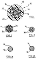
- FIGURE 1 illustrates the transversal cross-section of a communication cable 10 which comprises a single steel wire 12 as tensile member in its center.
- the steel wire 12 is coated with a layer 14 of polyester.
- Optical fibres 16 within a polyethylene jacket 18 are arranged around the tensile member.
- a supplementary protection is provided by means of a thin layer 20 of paper tapes and/or aluminium and the whole is covered by a polyethylene sheath 22.
- FIGURE 2 illustrates part of a communication cable of the slotted core type.
- a 2+2-strand 24, 26 functions as tensile member.
- the 2+2-strand has a group of two twisted wires 24 and a group of two untwisted wires 26. The first group and the second group are twisted around each other.
- a sheath of polyester 14 is provided around the 2+2-strand 24, 26 and the whole is surrounded by a layer of polyethylene 28 where slots are made to locate the optical fibres.
- FIGURE 3 illustrates a transversal cross-section of a tensile member formed by a 1x2-strand.
- the 1x2-strand is formed by two twisted steel wires 30.
- a standard test to evaluate the adhesion or bond between the synthetic coating and the tensile member is carried out as follows. Referring to FIGURE 4a, a length of a steel wire 12 with a synthetic coating 14 is taken. The synthetic coating 14 is removed in the longitudinal direction over about five cm length on both sides of the wire, diametrically towards each other by means of the sharp side of a cutting knife. A cross-section such as shown in FIGURE 4b is obtained. By means of the blunt side of the cutting knife the synthetic coating 14 is slightly lifted. Finally, the synthetic coating is tried with the fingers to be pulled off the steel wire. An evaluation is made according to following observations : Rating Description 0 more than excellent None can be removed from the wire, the lifted coating breaks right away when pulling.
- All tested tensile members obtaining a rating of 0,1 or 2 are within the scope of the present invention and have a strong adhesion between the tensile member and the synthetic coating.
- the above standard adhesion test is applied to an individual wire of the steel strand.
- the method of manufacturing a tensile member for use in a communication cable according to the invention is straightforward.
- the steel wire or wires are drawn until their final diameter and, in case of a strand embodiment, are twisted to the strand.
- the surface of the wire(s) is properly cleaned, the wire or the strand is heated and is coated with a synthetic coating by means of a well known extrusion process.
- a zinc coating is avoided on the steel wires before extrusion, but the steel wires may be covered with up to 2.5 g/m 2 of phosphate, which is substantially lower than the amounts disclosed in US-A-5 344 713.
- the extruded synthetic material preferably has a melt viscosity measured at about 280 °C ranging from 100 Pa.s to 2500 Pa.s for a corresponding shear rate going down from 10000 1/s to 1 1/s.
- a still more preferable value is a melt viscosity ranging from 200 Pa.s to 1000 Pa.s for a corresponding shear rate going down from 5000 1/s to 20 1/s.
- the stranding step and the extrusion step may be done within the same manufacturing line.
- normality refers to a concentration of a solution expressed in gram-equivalents of active material per dm 3 of solution.
- a supplemental advantage of a PET coating is that it has an improved resistance against ageing if compared with e.g. a PE coating. This can be demonstrated by measuring the impedance of the coating.
- the impedance of a PET coating remains relatively stable in time whereas the impedance of a PE coating drops in the first 200 hours. This is due to cracks and pores caused by the water absorption of PE.
- a suitable steel composition for the tensile member may be along following lines.
- the carbon content ranges from 0.40 to 0.85 per cent
- the manganese content ranges from 0.30 to 0.90 per cent
- the silicon content ranges from 0.15 to 0.50 per cent.
- the sulphur content and the phosphorus content are each kept below 0.05 per cent.
- the breaking load of the steel strand is at least 3500 Newton and the tensile strength of the steel wires is at least 1300 MPa.
- the modulus of elasticity of the strand embodiment is at least 150 000 MPa, the modulus of elasticity of the steel wire embodiment is at least 190 000 MPa.
Landscapes
- Physics & Mathematics (AREA)
- General Physics & Mathematics (AREA)
- Optics & Photonics (AREA)
- Ropes Or Cables (AREA)
- Optical Fibers, Optical Fiber Cores, And Optical Fiber Bundles (AREA)
Priority Applications (5)
| Application Number | Priority Date | Filing Date | Title |
|---|---|---|---|
| EP97203108A EP0908748A1 (fr) | 1997-10-07 | 1997-10-07 | Câble de communication avec armature de tension mécanique amélioré |
| BRPI9812900-7A BR9812900B1 (pt) | 1997-10-07 | 1998-10-01 | cabo de comunicação. |
| PCT/EP1998/006248 WO1999018464A1 (fr) | 1997-10-07 | 1998-10-01 | Cable de communication pourvu d'un element resistant ameliore |
| CN98811753.3A CN1280678A (zh) | 1997-10-07 | 1998-10-01 | 带有改进的抗拉伸件的通讯光缆 |
| EP98950101A EP1019766A1 (fr) | 1997-10-07 | 1998-10-01 | Cable de communication pourvu d'un element resistant ameliore |
Applications Claiming Priority (1)
| Application Number | Priority Date | Filing Date | Title |
|---|---|---|---|
| EP97203108A EP0908748A1 (fr) | 1997-10-07 | 1997-10-07 | Câble de communication avec armature de tension mécanique amélioré |
Publications (1)
| Publication Number | Publication Date |
|---|---|
| EP0908748A1 true EP0908748A1 (fr) | 1999-04-14 |
Family
ID=8228800
Family Applications (2)
| Application Number | Title | Priority Date | Filing Date |
|---|---|---|---|
| EP97203108A Withdrawn EP0908748A1 (fr) | 1997-10-07 | 1997-10-07 | Câble de communication avec armature de tension mécanique amélioré |
| EP98950101A Ceased EP1019766A1 (fr) | 1997-10-07 | 1998-10-01 | Cable de communication pourvu d'un element resistant ameliore |
Family Applications After (1)
| Application Number | Title | Priority Date | Filing Date |
|---|---|---|---|
| EP98950101A Ceased EP1019766A1 (fr) | 1997-10-07 | 1998-10-01 | Cable de communication pourvu d'un element resistant ameliore |
Country Status (4)
| Country | Link |
|---|---|
| EP (2) | EP0908748A1 (fr) |
| CN (1) | CN1280678A (fr) |
| BR (1) | BR9812900B1 (fr) |
| WO (1) | WO1999018464A1 (fr) |
Families Citing this family (1)
| Publication number | Priority date | Publication date | Assignee | Title |
|---|---|---|---|---|
| CN102254065B (zh) * | 2011-06-29 | 2013-03-20 | 西安电子科技大学 | 双极型晶体管参数提取方法及其等效电路 |
Citations (5)
| Publication number | Priority date | Publication date | Assignee | Title |
|---|---|---|---|---|
| US4076382A (en) * | 1975-11-12 | 1978-02-28 | Siemens Aktiengesellschaft | Optical cable with plastic multilayer sheath |
| JPS6066136A (ja) * | 1983-09-20 | 1985-04-16 | Tatsuta Electric Wire & Cable Co Ltd | 半導電層の剥離試験方法 |
| US4557560A (en) * | 1983-11-15 | 1985-12-10 | At&T Technologies, Inc. | Rodent and lightning protective sheath system for cables |
| EP0402895A1 (fr) * | 1989-06-13 | 1990-12-19 | Sumitomo Electric Industries, Ltd. | Fibres optiques revêtues hermétiquement et fabrication de ces fibres |
| JPH06194304A (ja) * | 1992-12-22 | 1994-07-15 | Sumitomo Electric Ind Ltd | 絶縁電線における絶縁被膜の密着力評価方法 |
-
1997
- 1997-10-07 EP EP97203108A patent/EP0908748A1/fr not_active Withdrawn
-
1998
- 1998-10-01 BR BRPI9812900-7A patent/BR9812900B1/pt not_active IP Right Cessation
- 1998-10-01 WO PCT/EP1998/006248 patent/WO1999018464A1/fr not_active Ceased
- 1998-10-01 EP EP98950101A patent/EP1019766A1/fr not_active Ceased
- 1998-10-01 CN CN98811753.3A patent/CN1280678A/zh active Pending
Patent Citations (5)
| Publication number | Priority date | Publication date | Assignee | Title |
|---|---|---|---|---|
| US4076382A (en) * | 1975-11-12 | 1978-02-28 | Siemens Aktiengesellschaft | Optical cable with plastic multilayer sheath |
| JPS6066136A (ja) * | 1983-09-20 | 1985-04-16 | Tatsuta Electric Wire & Cable Co Ltd | 半導電層の剥離試験方法 |
| US4557560A (en) * | 1983-11-15 | 1985-12-10 | At&T Technologies, Inc. | Rodent and lightning protective sheath system for cables |
| EP0402895A1 (fr) * | 1989-06-13 | 1990-12-19 | Sumitomo Electric Industries, Ltd. | Fibres optiques revêtues hermétiquement et fabrication de ces fibres |
| JPH06194304A (ja) * | 1992-12-22 | 1994-07-15 | Sumitomo Electric Ind Ltd | 絶縁電線における絶縁被膜の密着力評価方法 |
Non-Patent Citations (2)
| Title |
|---|
| PATENT ABSTRACTS OF JAPAN vol. 009, no. 203 (P - 381) 21 August 1985 (1985-08-21) * |
| PATENT ABSTRACTS OF JAPAN vol. 018, no. 539 (P - 1812) 13 October 1994 (1994-10-13) * |
Also Published As
| Publication number | Publication date |
|---|---|
| CN1280678A (zh) | 2001-01-17 |
| BR9812900A (pt) | 2000-08-08 |
| EP1019766A1 (fr) | 2000-07-19 |
| BR9812900B1 (pt) | 2009-12-01 |
| WO1999018464A1 (fr) | 1999-04-15 |
Similar Documents
| Publication | Publication Date | Title |
|---|---|---|
| US5408560A (en) | Tensile member for communication cables | |
| US8525031B2 (en) | Low cost, high performance flexible reinforcement for communications cable | |
| TWI666471B (zh) | 光纖帶芯線及光纖纜線 | |
| US6198865B1 (en) | Telecommunications cable having good adhesion between a protective jacket and strength members | |
| US20020041743A1 (en) | Aerial cable containing optical transmission elements and process for the manufacture of an aerial cable | |
| EP0595535A1 (fr) | Câble blindé sous-marin | |
| US8406591B2 (en) | Low cost, high performance, low profile flexible reinforcement for communications cable | |
| US20110089588A1 (en) | Water-blocked optical cable and process for the production thereof | |
| EP0290082B1 (fr) | Structure de câblé acier compact | |
| US7180000B2 (en) | Low cost, high performance, flexible, water-swellable reinforcement for communications cable | |
| CN1561465A (zh) | 光纤电缆 | |
| CN1697989A (zh) | 干管光纤组件、电缆、及其制造方法 | |
| US6256439B1 (en) | Lubricant for central core fiber optic cable having stranded ribbons | |
| AU2016201461A1 (en) | Fiber optic cables with extruded access features for access to a cable cavity | |
| US7435909B2 (en) | Low cost, high performance flexible reinforcement for communications cable | |
| KR20050026689A (ko) | 중간 필라멘트가 폴리머로 코팅된 다층 스틸 코드 | |
| EP0182538B1 (fr) | Câble de télécommunication contenant des fibres optiques | |
| US20030072545A1 (en) | Drop cable and method of fabricating same | |
| EP0908748A1 (fr) | Câble de communication avec armature de tension mécanique amélioré | |
| US20130259434A1 (en) | Overmold bonding system for fiber optic cable | |
| DE2801231A1 (de) | Elastomere-isolierte, elastomere- ummantelte starkstromtrosse, kabel, seil o.dgl. | |
| EP0614197B1 (fr) | Cables de transmission comportant un élément porteur, élément porteur destiné à des tels cables et procédé de fabrication d'un tel élément porteur. | |
| AT394115B (de) | Luftkabel mit einer lichtwellenleiter enthaltenden seele und verfahren zur herstellung desselben | |
| DE19910653A1 (de) | Metallfreies optisches Kabel | |
| AU2011253639B2 (en) | Water-blocked optical cable and process for the production thereof |
Legal Events
| Date | Code | Title | Description |
|---|---|---|---|
| PUAI | Public reference made under article 153(3) epc to a published international application that has entered the european phase |
Free format text: ORIGINAL CODE: 0009012 |
|
| AK | Designated contracting states |
Kind code of ref document: A1 Designated state(s): AT BE CH DE DK ES FI FR GB GR IE IT LI LU MC NL PT SE |
|
| AX | Request for extension of the european patent |
Free format text: AL;LT;LV;RO;SI |
|
| AKX | Designation fees paid | ||
| STAA | Information on the status of an ep patent application or granted ep patent |
Free format text: STATUS: THE APPLICATION IS DEEMED TO BE WITHDRAWN |
|
| 18D | Application deemed to be withdrawn |
Effective date: 19991015 |
|
| REG | Reference to a national code |
Ref country code: DE Ref legal event code: 8566 |