EP0908838A2 - Verfahren zur Datenübertragung zwischen einem Schreib-Lesegerät und einem Transponder - Google Patents
Verfahren zur Datenübertragung zwischen einem Schreib-Lesegerät und einem Transponder Download PDFInfo
- Publication number
- EP0908838A2 EP0908838A2 EP98117098A EP98117098A EP0908838A2 EP 0908838 A2 EP0908838 A2 EP 0908838A2 EP 98117098 A EP98117098 A EP 98117098A EP 98117098 A EP98117098 A EP 98117098A EP 0908838 A2 EP0908838 A2 EP 0908838A2
- Authority
- EP
- European Patent Office
- Prior art keywords
- field strength
- frequency
- time base
- changes
- evaluating
- Prior art date
- Legal status (The legal status is an assumption and is not a legal conclusion. Google has not performed a legal analysis and makes no representation as to the accuracy of the status listed.)
- Withdrawn
Links
Images
Classifications
-
- G—PHYSICS
- G06—COMPUTING OR CALCULATING; COUNTING
- G06K—GRAPHICAL DATA READING; PRESENTATION OF DATA; RECORD CARRIERS; HANDLING RECORD CARRIERS
- G06K7/00—Methods or arrangements for sensing record carriers, e.g. for reading patterns
- G06K7/0008—General problems related to the reading of electronic memory record carriers, independent of its reading method, e.g. power transfer
Definitions
- the invention relates to a method for data transmission between a read / write device and a transponder the preamble of claim 1 and a device for Implementation of the method according to the preamble of the claims 11 to 13.
- the transponder is a data store whose information read wirelessly with the read / write device and can be changed.
- the information is transmitted magnetically or electromagnetically. From the reader to the transponder, it is through Field strength change of a high-frequency carrier and evaluation the times between successive changes in field strength performed.
- the first requirement is for active transponder systems with its own energy supply to achieve one if possible long battery life and with passive transponder systems with energy supply from the magnetic or electromagnetic Field of the read / write device to achieve a the greatest possible range.
- the second requirement is important because of the size of the transponder and the manufacturing costs.
- only one RC oscillator can be used with all frequency-determining components on one Silicon chip can be integrated.
- This RC oscillator is principally due to the manufacturing process as well as the typical temperature and Voltage range a frequency tolerance of up to +/- 30 % based on its nominal value dimensioned in the chip design on.
- the oscillator could be calibrated after chip production trimmed with a laser beam or over memory cells be adjusted. But this is complex and also has the disadvantage that frequency tolerances by temperature and Changes in voltage cannot be compensated.
- the invention has for its object a method for Data transfer between a read / write device and a Transponder and a device for performing the method to improve that the accuracy of one as Time base for the evaluation of the times between the field strength changes serving frequency increased and thereby a higher data rate is made possible.
- the field strength changes include switching on and off of a field as well as the partial subsidence or Understanding the increase in field strength of a field.
- the solution is particularly advantageous as it is in the breaks, i.e. when the device is switched off Field, no possibility of synchronization z. B. with the RF carrier of the read / write device and thus needs its own exact time base in the transponder becomes.
- the solution according to the invention achieves a smaller one Ratio of the pulse duration of long and short pulses that in turn defined by the times between changes in field strength are to be achieved by shortening the long pulses and thereby reduce the period of the data signals and increase the data rate.
- a signal is preferably used for the initial calibration transmitted, the time intervals between the field strength changes are predefined.
- the calibration signals can by their temporal arrangement in the Signal telegram can be specified or by their coding deviate from data signals.
- the calibration signal can be replaced by two consecutive ones Field strength changes be limited pulse, its length greater than the period of the subsequent data signals is.
- the calibration signal contains the information of a Target frequency for the time base with which the actual frequency the time base compared and corrected to the target frequency can be. Since the actual frequency can be recorded digitally and the target frequency is known, the deviation can be immediate determined and also targeted the necessary correction in one step be carried out. Then already exists sufficient accuracy for correct decoding during data transmission.
- this is additionally during the data transmission detects the deviation from the target value and corrects the correction value obtained at the beginning.
- the time base is also subject to dynamic influences corrected, for example with passive transponders with power supply from the field of the read / write device may occur. That is the case when the distance between the transponder and the read / write device during data transmission is changed and thereby also the supply voltage fluctuates.
- a change in voltage can also occur active transponders by depleting the battery.
- Thermal influences can also be compensated like they are e.g. B. arise when transponders manually in the field of Read-write device can be spent and then exposed to body heat heat.
- this can be used as a time base for the evaluation of the times between the field strength changes serving frequency generated by a free-running oscillator and one or more for its calibration the frequency-determining components are changed.
- the division ratio of one downstream frequency divider is changed.
- the second alternative works purely digital and enables the targeted calibration of the time base. Since only digitage for this Circuits are needed that are easy on Having a chip integrated, this additional effort is eliminated not important in practice.
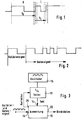
- FIG. 1 shows a time diagram with a representation of different ones logical states and time tolerances of a data signal.
- the different logical states correspond an on or off RF carrier.
- a bit with the value "0” is due to a long period Change of the logic states and a bit with the significance "1" by a short period of a change of the logical States defined.
- a common form of digital decoding of data can be performed by counting the pulses from an oscillator which are within the respective periods for the Bit "0" or "1" can be generated.
- the counter reading is in each case evaluated after a period of the data signal.
- Varying the oscillator frequency results in different ones Meter readings for the same period. At the period becomes too great a deviation from the standard value decoded incorrectly.
- T0 and T1 and / or their ratio chosen very large, the inaccuracy of the reference oscillator to be caught.
- the disadvantage is one small data rate. With a shorter period and / or a smaller ratio T0 / T1 can be a higher one Data rate can be achieved. If the oscillator frequency though is inaccurate, may no longer be between the period be distinguished from T0 and T1 so that the decoding of the data signal becomes faulty.
- Fig. 2 shows a timing diagram with a representation of the logical States of a leading calibration signal and subsequent ones Data signals as used in the invention for calibration the time base is used.
- Each or at least the first transferred data record extended by a calibration signal has at least the length of an expected period of the data signal.
- the calibration signal has at least the length of an expected period of the data signal.
- There is a permanently programmed counter reading in the decoder the as the setpoint for the evaluation of the calibration signal serves. From the difference between the stored setpoint and the actual counter reading in the decoder will then turn on Correction value calculated.
- FIG. 3 shows a simplified block diagram of a decoder of a transponder.
- An input 10 of an evaluation circuit 12 becomes a leading calibration signal and subsequent Data signals existing signal, as is exemplary is shown in Fig. 2 supplied.
- the evaluation circuit 12 a clock is supplied via a clock input 14, that by means of an RC oscillator 16 and a subsequent one programmable divider 18 is obtained.
- the programmable divider 18 is first at an initial value set. After recognizing and evaluating the calibration signal is based on the determined correction value a pending at a control output 20 of the evaluation circuit 12 Control signal the programmable divider 18 is set so that with unchanged frequency of the RC oscillator 16 the clock supplied to the evaluation circuit 12 is now exactly the Target frequency corresponds.
- the data following the calibration signal are now correct evaluated and appear as binary data at data output 22 the evaluation circuit 12.
- the minimum data rate is limited by the positive tolerance of approx. + 30% and the maximum possible divisor factor of the programmable divider 18.
- the evaluation circuit 12 also from the mean period of several periods of Data signal determine current correction values and the division ratio of the programmable divider 18, if necessary track.
Landscapes
- Engineering & Computer Science (AREA)
- Artificial Intelligence (AREA)
- Computer Vision & Pattern Recognition (AREA)
- Physics & Mathematics (AREA)
- General Physics & Mathematics (AREA)
- Theoretical Computer Science (AREA)
- Radar Systems Or Details Thereof (AREA)
- Near-Field Transmission Systems (AREA)
- Electric Clocks (AREA)
Abstract
Description
- Fig. 1
- ein Zeitdiagramm mit einer Darstellung unterschiedlicher logischer Zustände und Zeittoleranzen eines Datensignals,
- Fig. 2
- ein Zeitdiagramm mit einer Darstellung der logischen Zustände eines führenden Kalibriersignals und nachfolgender Datensignale und
- Fig. 3
- ein vereinfachtes Blockschaltbild eines Dekoders eines Transponders.
Claims (13)
- Verfahren zur Datenübertragung zwischen einem Schreib-Lesegerät und einem Transponder durch Feldstärkeänderung eines elektromagnetischen oder magnetischen Feldes und Auswertung der Zeiten zwischen wenigstens zwei aufeinanderfolgenden Feldstärkeänderungen, dadurch gekennzeichnet, daß eine als Zeitbasis für die Auswertung der Zeiten zwischen den Feldstärkeänderungen dienende Frequenz zumindest zu Beginn einer Datenübertragung so kalibriert wird, daß sie in einer vorgegebenen Beziehung zur Periodendauer der Feldstärkeänderungen steht.
- Verfahren nach Anspruch 1, dadurch gekennzeichnet, daß zur anfänglichen Kalibrierung ein Signal übermittelt wird, dessen Zeitabstände zwischen den Feldstärkeänderungen vordefiniert sind.
- Verfahren nach Anspruch 2, dadurch gekennzeichnet, daß die Kalibriersignale von Datensignalen abweichen.
- Verfahren nach Anspruch 3, dadurch gekennzeichnet, daß das zur anfänglichen Kalibrierung übermittelte Signal ein durch zwei aufeinanderfolgende Feldstärkeänderungen begrenzter Puls ist, dessen Länge größer als die Periodendauer der anschließenden Datensignale ist.
- Verfahren nach einem der Ansprüche 1 bis 4, dadurch gekennzeichnet, daß zur nachfolgenden oder dynamischen Kalibrierung die mittlere Periodendauer der über mehrere Perioden erfaßten Datensignale dient.
- Verfahren nach einem der Ansprüche 1 bis 5, dadurch gekennzeichnet, daß zumindest zu Beginn der Datenübertragung eine systematische Zeitabweichung von einem Sollwert, die durch die Ungenauigkeit einer zur Auswertung benutzten, internen Zeitbasis auftritt, erfaßt wird und daraus ein Korrekturwert ermittelt wird, mit dem die interne Zeitbasis kalibriert wird.
- Verfahren nach Anspruch 6, dadurch gekennzeichnet, daß zusätzlich während der Datenübertragung die Abweichung vom Sollwert erfaßt wird und der zu Beginn gewonnene Korrekturwert korrigiert wird.
- Verfahren nach einem oder mehreren der Ansprüche 1 bis 7, dadurch gekennzeichnet, daß die als Zeitbasis für die für die Auswertung der Zeiten zwischen den Feldstärkeänderungen dienende Frequenz von einem freischwingenden Oszillator (16) erzeugt wird und zu dessen Kalibrierung eines oder mehrere der frequenzbestimmenden Bauteile verändert werden.
- Verfahren nach einem oder mehreren der Ansprüche 1 bis 7, dadurch gekennzeichnet, daß die als Zeitbasis für die für die Auswertung der Zeiten zwischen den Feldstärkeänderungen dienende Frequenz von einem freischwingenden Oszillator (16) erzeugt wird und zu dessen Kalibrierung das Teilerverhältnis eines nachgeschalteten Frequenzteilers (18) verändert wird.
- Verfahren nach einem oder mehreren der Ansprüche 1 bis 7, dadurch gekennzeichnet, daß die als Zeitbasis für die für die Auswertung der Zeiten zwischen den Feldstärkeänderungen dienende Frequenz von einem freischwingenden Oszillator (16) erzeugt wird und zu dessen Kalibrierung eines oder mehrere der frequenzbestimmenden Bauteile verändert werden und das Teilerverhältnis eines nachgeschalteten Frequenzteilers (18) verändert wird.
- Vorrichtung zur Durchführung des Verfahrens nach einem oder mehreren der Ansprüche 1 bis 7, dadurch gekennzeichnet, daß ein freischwingender Oszillator (16) vorgesehen ist, der als Zeitbasis für die Auswertung der Zeiten zwischen den Feldstärkeänderungen dienende Frequenz dient, und zur Kalibrierung der Zeitbasis eines oder mehrere der frequenzbestimmenden Bauteile verändert werden.
- Vorrichtung zur Durchführung des Verfahrens nach einem oder mehreren der Ansprüche 1 bis 7, dadurch gekennzeichnet, daß ein freischwingender Oszillator (16) vorgesehen ist, der als Zeitbasis für die Auswertung der Zeiten zwischen den Feldstärkeänderungen dienende Frequenz dient, und zur Kalibrierung der Zeitbasis das Teilerverhältnis eines nachgeschalteten Frequenzteilers (18) verändert wird.
- Vorrichtung zur Durchführung des Verfahrens nach einem oder mehreren der Ansprüche 1 bis 7, dadurch gekennzeichnet, daß ein freischwingender Oszillator (16) vorgesehen ist, der als Zeitbasis für die Auswertung der Zeiten zwischen den Feldstärkeänderungen dienende Frequenz dient, und zur Kalibrierung der Zeitbasis eines oder mehrere der frequenzbestimmenden Bauteile verändert werden und das Teilerverhältnis eines nachgeschalteten Frequenzteilers (18) verändert wird.
Applications Claiming Priority (2)
| Application Number | Priority Date | Filing Date | Title |
|---|---|---|---|
| DE19744781A DE19744781C2 (de) | 1997-10-10 | 1997-10-10 | Verfahren zur Datenübertragung zwischen einem Schreib-Lesegerät und einem Transponder sowie Vorrichtung zur Durchführung des Verfahrens |
| DE19744781 | 1997-10-10 |
Publications (2)
| Publication Number | Publication Date |
|---|---|
| EP0908838A2 true EP0908838A2 (de) | 1999-04-14 |
| EP0908838A3 EP0908838A3 (de) | 2002-07-03 |
Family
ID=7845152
Family Applications (1)
| Application Number | Title | Priority Date | Filing Date |
|---|---|---|---|
| EP98117098A Withdrawn EP0908838A3 (de) | 1997-10-10 | 1998-09-09 | Verfahren zur Datenübertragung zwischen einem Schreib-Lesegerät und einem Transponder |
Country Status (3)
| Country | Link |
|---|---|
| US (1) | US6044333A (de) |
| EP (1) | EP0908838A3 (de) |
| DE (1) | DE19744781C2 (de) |
Cited By (5)
| Publication number | Priority date | Publication date | Assignee | Title |
|---|---|---|---|---|
| US6396438B1 (en) | 1999-09-24 | 2002-05-28 | Slc Technologies | System and method for locating radio frequency identification tags using three-phase antenna |
| US6452504B1 (en) | 1999-09-24 | 2002-09-17 | Ge Interlogix, Inc. | System and method for communication with radio frequency identification tags using tow message DFM protocol |
| US6661335B1 (en) | 1999-09-24 | 2003-12-09 | Ge Interlogix, Inc. | System and method for locating radio frequency identification tags |
| US6693511B1 (en) | 1999-09-24 | 2004-02-17 | Ge Interlogix, Inc. | System and method for communicating with dormant radio frequency identification tags |
| WO2007060454A1 (en) * | 2005-11-24 | 2007-05-31 | Stmicroelectronics (Research & Development) Limited | Calibrated pulsed serial link |
Families Citing this family (19)
| Publication number | Priority date | Publication date | Assignee | Title |
|---|---|---|---|---|
| EP1018692B1 (de) | 1999-01-08 | 2006-06-28 | Anatoli Stobbe | Sicherungssystem, Transponder und Empfangsvorrichtung |
| DE10004922A1 (de) * | 2000-02-04 | 2001-08-09 | Giesecke & Devrient Gmbh | Transponder, insbesondere für eine kontaktlose Chipkarte |
| DE10050878B4 (de) * | 2000-10-13 | 2012-07-12 | Atmel Automotive Gmbh | Verfahren zur Übertragung von mehreren Informationssymbolen |
| EP1358644A4 (de) * | 2000-12-29 | 2009-09-23 | Tagsys Sa | Vorrichtung und verfahren zur abfrage von etiketten |
| DE10138217A1 (de) | 2001-08-03 | 2003-03-20 | Atmel Germany Gmbh | Verfahren zur Übertragung von Daten |
| DE10138218B4 (de) * | 2001-08-03 | 2004-01-22 | Atmel Germany Gmbh | Verfahren zur Übertragung von Daten |
| DE10204317A1 (de) * | 2002-02-01 | 2003-08-14 | Atmel Germany Gmbh | Verfahren zur Übertragung von Daten |
| DE10204347A1 (de) * | 2002-02-01 | 2003-08-14 | Atmel Germany Gmbh | Verfahren zur Übertragung von Daten |
| DE10335003A1 (de) * | 2003-07-23 | 2005-02-10 | Atmel Germany Gmbh | Verfahren zur drahtlosen Datenübertragung zwischen einer Basisstation und einem Transponder |
| DE10335009A1 (de) * | 2003-07-23 | 2005-02-10 | Atmel Germany Gmbh | Verfahren zur drahtlosen Datenübertragung zwischen einer Basisstation und einem Transponder |
| GB2415555B (en) * | 2004-06-26 | 2008-05-28 | Plus Design Ltd | Signalling method |
| DE102004062132A1 (de) * | 2004-12-23 | 2006-07-13 | Atmel Germany Gmbh | Backscatter Transponder |
| US20070122920A1 (en) * | 2005-11-29 | 2007-05-31 | Bornstein William B | Method for improved control of critical dimensions of etched structures on semiconductor wafers |
| US8018323B2 (en) * | 2006-01-30 | 2011-09-13 | Baohua Qi | RFID sensor device based on pulse-processing |
| DE102006007262B3 (de) * | 2006-02-10 | 2007-05-10 | Atmel Germany Gmbh | Verfahren zur drahtlosen Datenübertragung zwischen einer Basisstation und einem Transponder mittels induktiver Kopplung |
| US8013714B2 (en) * | 2006-03-27 | 2011-09-06 | Baohua Qi | RFID sensor using pulse processing |
| DE102006057602B3 (de) * | 2006-11-27 | 2008-04-10 | Atmel Germany Gmbh | Verfahren zur drahtlosen Datenübertragung zwischen einer Basisstation und einem passiven Transponder sowie passiver Transponder |
| US8026795B2 (en) * | 2007-02-22 | 2011-09-27 | Baohua Qi | RFID sensor array and sensor group based on pulse-processing |
| US7744691B2 (en) * | 2007-04-10 | 2010-06-29 | Calcium Silicate Corporation | Energy conserving pozzolan compositions and cements incorporating same |
Family Cites Families (16)
| Publication number | Priority date | Publication date | Assignee | Title |
|---|---|---|---|---|
| US3944928A (en) * | 1974-07-01 | 1976-03-16 | Microlab/Fxr | Harmonic communication system |
| US4206421A (en) * | 1976-09-17 | 1980-06-03 | Siemens Aktiengesellschaft | Arrangement for synchronizing a free-swinging oscillator |
| GB1577920A (en) * | 1976-11-01 | 1980-10-29 | Nedap Nv | Detection plate for identification systems |
| US4398195A (en) * | 1979-07-02 | 1983-08-09 | Del Norte Technology, Inc. | Method of and apparatus for guiding agricultural aircraft |
| US4327441A (en) * | 1980-03-31 | 1982-04-27 | Texas Instruments Incorporated | Method and apparatus for synchronizing and calibrating a receiver to a pulse width modulation transmitter |
| DE3412610A1 (de) * | 1984-04-04 | 1985-10-17 | Gebhard Balluff Fabrik feinmechanischer Erzeugnisse GmbH & Co, 7303 Neuhausen | Verfahren zur datenuebertragung und datenuebertragungssystem |
| DE3500363A1 (de) * | 1985-01-08 | 1986-07-10 | Licentia Patent-Verwaltungs-Gmbh, 6000 Frankfurt | Anordnung zur synchronisation eines digitalen datenempfaengers |
| NL8601021A (nl) * | 1986-04-22 | 1987-11-16 | Nedap Nv | Programmeerbare responder. |
| NL8901659A (nl) * | 1989-06-30 | 1991-01-16 | Nedap Nv | Multipassysteem. |
| DE4107640A1 (de) * | 1991-03-09 | 1992-09-10 | Standard Elektrik Lorenz Ag | Rahmensynchronisation durch korrelation |
| DE4134922C1 (de) * | 1991-10-23 | 1992-12-03 | Anatoli 3013 Barsinghausen De Stobbe | |
| DE69323460T2 (de) * | 1992-09-07 | 1999-07-08 | Denso Corp., Kariya, Aichi | Kommunikationssystem |
| US5450088A (en) * | 1992-11-25 | 1995-09-12 | Texas Instruments Deutschland Gmbh | Transponder arrangement |
| EP0625714A1 (de) * | 1993-05-19 | 1994-11-23 | Texas Instruments Deutschland Gmbh | Verfahren zum Senden eines in einer Transpondervorrichtung gespeicherten Datenberichts an eines Abfragevorrichtung |
| DE19526353A1 (de) * | 1995-07-19 | 1997-01-23 | Anatoli Stobbe | Verfahren zur automatischen Identifikation einer unbekannten Anzahl von Transpondern durch einen Leser sowie Identifikationssystem zur Durchführung des Verfahrens |
| US5889491A (en) * | 1997-08-05 | 1999-03-30 | Minter; Jerry B. | Calibration for pilot warning system |
-
1997
- 1997-10-10 DE DE19744781A patent/DE19744781C2/de not_active Expired - Fee Related
-
1998
- 1998-09-09 EP EP98117098A patent/EP0908838A3/de not_active Withdrawn
- 1998-10-13 US US09/170,569 patent/US6044333A/en not_active Expired - Fee Related
Cited By (5)
| Publication number | Priority date | Publication date | Assignee | Title |
|---|---|---|---|---|
| US6396438B1 (en) | 1999-09-24 | 2002-05-28 | Slc Technologies | System and method for locating radio frequency identification tags using three-phase antenna |
| US6452504B1 (en) | 1999-09-24 | 2002-09-17 | Ge Interlogix, Inc. | System and method for communication with radio frequency identification tags using tow message DFM protocol |
| US6661335B1 (en) | 1999-09-24 | 2003-12-09 | Ge Interlogix, Inc. | System and method for locating radio frequency identification tags |
| US6693511B1 (en) | 1999-09-24 | 2004-02-17 | Ge Interlogix, Inc. | System and method for communicating with dormant radio frequency identification tags |
| WO2007060454A1 (en) * | 2005-11-24 | 2007-05-31 | Stmicroelectronics (Research & Development) Limited | Calibrated pulsed serial link |
Also Published As
| Publication number | Publication date |
|---|---|
| EP0908838A3 (de) | 2002-07-03 |
| US6044333A (en) | 2000-03-28 |
| DE19744781C2 (de) | 2000-03-02 |
| DE19744781A1 (de) | 1999-04-15 |
Similar Documents
| Publication | Publication Date | Title |
|---|---|---|
| EP0908838A2 (de) | Verfahren zur Datenübertragung zwischen einem Schreib-Lesegerät und einem Transponder | |
| DE4107311C2 (de) | Verfahren zur drahtlosen Übertragung von Daten auf einen Datenträger | |
| DE4123828C2 (de) | Berührungslos arbeitender Näherungsschalter | |
| DE69233019T2 (de) | Kontaktlose IC-Karte | |
| DE10209804A1 (de) | Eine abtastbasierte Mehrfachringoszillatorstruktur für eine Chip-interne Geschwindigkeitsmessung | |
| DE4237112A1 (de) | ||
| DE4328100A1 (de) | Signalempfangsspule und IC-Karte vom kontaktlosen Typ, welche die Signalempfangsspule verwendet | |
| EP0483296B1 (de) | Verfahren zum auswerten binärer informationen einer magnetspeicherkarte | |
| DE102004005340A1 (de) | Verfahren zur Gewinnung von Zeitinformationen, Empfängerschaltung und Funkuhr | |
| EP0392182B1 (de) | Verfahren und Schaltung zur Auswertung von kontinuierlich auftretenden Zeitmarken | |
| DE2350991C2 (de) | ||
| DE4403124C2 (de) | Verfahren zum Betrieb einer Funkuhr | |
| DE102004004375B4 (de) | Verfahren zur Gewinnung von Zeitinformationen und Funkuhr | |
| DE2552079A1 (de) | Schaltungsanordnung zur bestimmung des mittelwertes einer frequenz | |
| DE2737467C2 (de) | Fernsteueranordnung | |
| DE2547885A1 (de) | Elektronischer zaehler | |
| EP0515438A1 (de) | Verfahren zum umsetzen einer analogen spannung in einen digitalwert. | |
| DE4035520C2 (de) | Verfahren und Anordnung zur Messung der Geschwindigkeit eines Fahrzeuges | |
| DE4210189C2 (de) | Vorrichtung und Verfahren zur Fernmessung der Temperatur | |
| EP1586917A2 (de) | Verfahren zur Auswahl eines oder mehrer Transponder | |
| DE102009042647A1 (de) | Elektronische Schaltung für Zeitgeberanwendungen kleinster Leistungsaufnahme und Verfahren zur Kalibrierung und zum Betreiben derselben | |
| DE2802867A1 (de) | Fernsteueranordnung | |
| DE3609064A1 (de) | Steuervorrichtung fuer den schreib/lesekopf einer aufnahme/wiedergabevorrichtung | |
| DE102007051792A1 (de) | Selbstkalibrierender RFID-Transponder | |
| WO2003054573A1 (de) | Feldgerät mit einem gps-modul |
Legal Events
| Date | Code | Title | Description |
|---|---|---|---|
| PUAI | Public reference made under article 153(3) epc to a published international application that has entered the european phase |
Free format text: ORIGINAL CODE: 0009012 |
|
| AK | Designated contracting states |
Kind code of ref document: A2 Designated state(s): AT BE CH CY DE DK ES FI FR GB GR IE IT LI LU MC NL PT SE |
|
| AX | Request for extension of the european patent |
Free format text: AL;LT;LV;MK;RO;SI |
|
| PUAL | Search report despatched |
Free format text: ORIGINAL CODE: 0009013 |
|
| AK | Designated contracting states |
Kind code of ref document: A3 Designated state(s): AT BE CH CY DE DK ES FI FR GB GR IE IT LI LU MC NL PT SE |
|
| AX | Request for extension of the european patent |
Free format text: AL;LT;LV;MK;RO;SI |
|
| RIC1 | Information provided on ipc code assigned before grant |
Free format text: 7G 06K 7/08 A, 7G 06K 7/00 B, 7G 06K 7/10 B, 7G 06K 7/016 B |
|
| 17P | Request for examination filed |
Effective date: 20021224 |
|
| AKX | Designation fees paid |
Designated state(s): DE FR GB |
|
| 17Q | First examination report despatched |
Effective date: 20030520 |
|
| STAA | Information on the status of an ep patent application or granted ep patent |
Free format text: STATUS: THE APPLICATION IS DEEMED TO BE WITHDRAWN |
|
| 18D | Application deemed to be withdrawn |
Effective date: 20040428 |