EP0908879A2 - Optisches Informationsspeichergerät - Google Patents
Optisches Informationsspeichergerät Download PDFInfo
- Publication number
- EP0908879A2 EP0908879A2 EP98105519A EP98105519A EP0908879A2 EP 0908879 A2 EP0908879 A2 EP 0908879A2 EP 98105519 A EP98105519 A EP 98105519A EP 98105519 A EP98105519 A EP 98105519A EP 0908879 A2 EP0908879 A2 EP 0908879A2
- Authority
- EP
- European Patent Office
- Prior art keywords
- light
- optical
- beam splitter
- polarization beam
- information storage
- Prior art date
- Legal status (The legal status is an assumption and is not a legal conclusion. Google has not performed a legal analysis and makes no representation as to the accuracy of the status listed.)
- Withdrawn
Links
Images


Classifications
-
- G—PHYSICS
- G11—INFORMATION STORAGE
- G11B—INFORMATION STORAGE BASED ON RELATIVE MOVEMENT BETWEEN RECORD CARRIER AND TRANSDUCER
- G11B7/00—Recording or reproducing by optical means, e.g. recording using a thermal beam of optical radiation by modifying optical properties or the physical structure, reproducing using an optical beam at lower power by sensing optical properties; Record carriers therefor
- G11B7/12—Heads, e.g. forming of the optical beam spot or modulation of the optical beam
- G11B7/135—Means for guiding the beam from the source to the record carrier or from the record carrier to the detector
- G11B7/1381—Non-lens elements for altering the properties of the beam, e.g. knife edges, slits, filters or stops
-
- G—PHYSICS
- G11—INFORMATION STORAGE
- G11B—INFORMATION STORAGE BASED ON RELATIVE MOVEMENT BETWEEN RECORD CARRIER AND TRANSDUCER
- G11B11/00—Recording on or reproducing from the same record carrier wherein for these two operations the methods are covered by different main groups of groups G11B3/00 - G11B7/00 or by different subgroups of group G11B9/00; Record carriers therefor
- G11B11/10—Recording on or reproducing from the same record carrier wherein for these two operations the methods are covered by different main groups of groups G11B3/00 - G11B7/00 or by different subgroups of group G11B9/00; Record carriers therefor using recording by magnetic means or other means for magnetisation or demagnetisation of a record carrier, e.g. light induced spin magnetisation; Demagnetisation by thermal or stress means in the presence or not of an orienting magnetic field
- G11B11/105—Recording on or reproducing from the same record carrier wherein for these two operations the methods are covered by different main groups of groups G11B3/00 - G11B7/00 or by different subgroups of group G11B9/00; Record carriers therefor using recording by magnetic means or other means for magnetisation or demagnetisation of a record carrier, e.g. light induced spin magnetisation; Demagnetisation by thermal or stress means in the presence or not of an orienting magnetic field using a beam of light or a magnetic field for recording by change of magnetisation and a beam of light for reproducing, i.e. magneto-optical, e.g. light-induced thermomagnetic recording, spin magnetisation recording, Kerr or Faraday effect reproducing
- G11B11/10532—Heads
- G11B11/10541—Heads for reproducing
- G11B11/10543—Heads for reproducing using optical beam of radiation
-
- G—PHYSICS
- G11—INFORMATION STORAGE
- G11B—INFORMATION STORAGE BASED ON RELATIVE MOVEMENT BETWEEN RECORD CARRIER AND TRANSDUCER
- G11B11/00—Recording on or reproducing from the same record carrier wherein for these two operations the methods are covered by different main groups of groups G11B3/00 - G11B7/00 or by different subgroups of group G11B9/00; Record carriers therefor
- G11B11/10—Recording on or reproducing from the same record carrier wherein for these two operations the methods are covered by different main groups of groups G11B3/00 - G11B7/00 or by different subgroups of group G11B9/00; Record carriers therefor using recording by magnetic means or other means for magnetisation or demagnetisation of a record carrier, e.g. light induced spin magnetisation; Demagnetisation by thermal or stress means in the presence or not of an orienting magnetic field
- G11B11/105—Recording on or reproducing from the same record carrier wherein for these two operations the methods are covered by different main groups of groups G11B3/00 - G11B7/00 or by different subgroups of group G11B9/00; Record carriers therefor using recording by magnetic means or other means for magnetisation or demagnetisation of a record carrier, e.g. light induced spin magnetisation; Demagnetisation by thermal or stress means in the presence or not of an orienting magnetic field using a beam of light or a magnetic field for recording by change of magnetisation and a beam of light for reproducing, i.e. magneto-optical, e.g. light-induced thermomagnetic recording, spin magnetisation recording, Kerr or Faraday effect reproducing
- G11B11/1055—Disposition or mounting of transducers relative to record carriers
- G11B11/10576—Disposition or mounting of transducers relative to record carriers with provision for moving the transducers for maintaining alignment or spacing relative to the carrier
-
- G—PHYSICS
- G11—INFORMATION STORAGE
- G11B—INFORMATION STORAGE BASED ON RELATIVE MOVEMENT BETWEEN RECORD CARRIER AND TRANSDUCER
- G11B7/00—Recording or reproducing by optical means, e.g. recording using a thermal beam of optical radiation by modifying optical properties or the physical structure, reproducing using an optical beam at lower power by sensing optical properties; Record carriers therefor
- G11B7/08—Disposition or mounting of heads or light sources relatively to record carriers
- G11B7/09—Disposition or mounting of heads or light sources relatively to record carriers with provision for moving the light beam or focus plane for the purpose of maintaining alignment of the light beam relative to the record carrier during transducing operation, e.g. to compensate for surface irregularities of the latter or for track following
- G11B7/0908—Disposition or mounting of heads or light sources relatively to record carriers with provision for moving the light beam or focus plane for the purpose of maintaining alignment of the light beam relative to the record carrier during transducing operation, e.g. to compensate for surface irregularities of the latter or for track following for focusing only
- G11B7/0909—Disposition or mounting of heads or light sources relatively to record carriers with provision for moving the light beam or focus plane for the purpose of maintaining alignment of the light beam relative to the record carrier during transducing operation, e.g. to compensate for surface irregularities of the latter or for track following for focusing only by astigmatic methods
Definitions
- the present invention generally relates to optical information storage apparatuses, and more particularly to an optical information storage apparatus which is suited for reproducing high-quality magneto-optic signals from a recording medium.
- an “information storage apparatus” refers to an apparatus which records information to and/or reproduces information from a recording medium.
- a light beam emitted from a light source is reflected by a plate-shaped polarization beam splitter and irradiated on a recording surface of an optical recording medium.
- the light beam which is reflected by the recording surface of the optical recording medium passes through the plate-shaped polarization beam splitter and is directed towards a photodetector.
- An astigmatism is generated when the reflected light beam from the optical recording medium passes through the plated shaped polarization beam splitter.
- this astigmatism is used to generate a focal error signal.
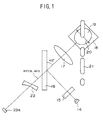
- FIG.1 is a plan view showing the general construction of an example of an optical system of the CD player.
- a light beam emitted from a semiconductor laser 14 is input to a diffraction grating 15, and ⁇ 1st order lights which are sub light beams used to detect a tracking error are generated.
- the light beam passing through the diffraction grating 15 is subjected to an amplitude division by a semitransparent mirror 16, and is reflected by the semi transparent mirror 16 depending on a reflectivity of the semi transparent mirror 16 and then input to a collimator lens 17.
- the collimator lens 17 converts the incoming light beam into parallel rays.
- the parallel rays from the collimator lens 17 are reflected in a direction perpendicular to the paper in FIG.1 by a mirror 18 and reach an objective lens 19 which stops the rays to a diffraction limit, thereby irradiating a pit 21 provided on the CD.
- an arrow 20 indicates a direction of an electric vector of the light irradiated on the CD.
- the direction 20 of the electric vector of the light irradiated on the CD is not very important, but this direction 20 is set to a 45° direction with respect to a row of the pits 21.
- the light reflected by the pit 21 is again input to the objective lens 19, and is passed through the collimator lens 17 to become a convergent light.
- This convergent light is subjected to an amplitude division by the semitransparent mirror 16, and is transmitted through the semitransparent mirror 16 depending on a transmittance of the semitransparent mirror 16.
- the light transmitted through the semitransparent mirror 16 generates an astigmatism and a coma aberration.
- the coma aberration is eliminated and only the astigmatism is extracted from the light transmitted through the semitransparent mirror 16, by passing the light from the semitransparent mirror 16 through a plano-concave lens 22 which is inclined in a direction opposite to the inclination of the semitransparent mirror 16.
- the light which passes through the plano-concave lens 22 is detected by a photodetector 23a, and a radio frequency (RF) signal, a focal error signal and a tracking error signal are generated based on an output of the photodetector 23a.
- RF radio frequency
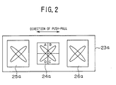
- FIG.2 is a plan view showing the general construction of the photodetector 23a on an enlarged scale.
- the photodetector 23a includes a 4-part detector 24a which is made up of detector parts A, B, C and D, a detector 25a, and a detector 26a.
- the RF signal is generated from a sum A+B+C+D of output photocurrents A, B, C and D of the detector parts A, B, C and D of the 4-part detector 24a.
- the focal error signal is generated from a difference between a sum A+C of the output photocurrents A and C of the detector parts A and C of the 4-part detector 24a, and a sum B+D of the output photocurrents B and D of the detector parts B and D of the 4-part detector 24a.
- the tracking error signal is generated from a difference between an output photocurrent of the detector 25a and an output photocurrent of the detector 26a.
- a push-pull signal which appears in a radial direction of the CD depending on the row of the pits 21 provided on the CD is generated in a direction indicated by an arrow in FIG.2. This push-pull signal is not used as a tracking error signal.
- the CD player is designed so that the direction in which the astigmatism is generated is inclined by approximately 45° with respect to a direction in which the signal of the CD flows.
- This design is employed because the push-pull signal appears in the radial direction of the CD due to the diffraction phenomenon when a spot of the light beam which is stopped to the diffraction limit is irradiated on the pit 21 of the CD.
- a frequency of this push-pull signal is determined by an amount of decentering, a rotational speed and a track pitch of the CD.
- a frequency band of the push-pull signal is approximately the same as a frequency band of the focal error signal which is obtained by the astigmatism method.
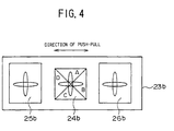
- FIG.3 is a diagram showing a case where a direction in which the astigmatism is generated in the CD player is parallel to a direction in which the signal of the CD flows.
- FIG.4 is a plan view showing the general construction of a photodetector 23b. In FIG. 3, those parts which are the same as those corresponding parts in FIG.1 are designated by the same reference numerals, and a description thereof will be omitted.
- the tracking error signal is generated from a difference between output photocurrents of detectors 25b and 26b of the photodetector 23b, and no inconvenience is introduced.
- detector parts A through D of a 4-part detector 24b that are used to generate the focal error signal must be arranged as shown in FIG.4. Accordingly, the direction in which the astigmatism is generated becomes parallel or perpendicular to the direction in which the push-pull signal is generated, and division lines (dark lines) of the 4-part detector 24b are inclined by 45° with respect to the direction in which the push-pull signal is generated. For this reason, the push-pull signal easily mixes into the focal error signal as a crosstalk, and a stable focal error signal cannot be obtained.
- the polarization direction of the light beam irradiated on the recording surface of the magneto-optic recording medium at the time of the signal reproduction is extremely important.
- the noise is reduced when the polarization direction of the light beam is parallel or perpendicular to a tracking guide groove which is provided on the magneto-optic recording medium. This noise reduction is due to the birefringence of a substrate and the shape of the groove of the magneto-optic recording medium.
- Another and more specific object of the present invention to provide an optical information storage apparatus which can generate a stable focal error signal and a tracking error signal, and detect a high-quality magneto-optic signal, using a relatively simple and inexpensive structure.
- Still another object of the present invention is to provide an optical information storage apparatus comprising a light source, a polarization beam splitter reflecting light emitted from the light source and irradiating a reflected light on a recording surface of a recording medium, and an optical element, made of an optically transparent material, having an input surface to which light reflected by the recording surface and transmitted through the polarization beam splitter is input, and an output surface from which light is output, where the optical element is inclined within a plane which is perpendicular to a light incident surface of the polarization beam splitter and includes an optical axis along which light travels, and the input surface and the output surface of the optical element are parallel to each other.
- the optical information storage apparatus of the present invention it is possible to generate a stable focal error signal and a tracking error signal, and to detect a high-quality magneto-optic signal, using a relatively simple and inexpensive structure.
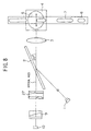
- FIG.5 is a plan view showing the general construction of an optical system of a first embodiment of an optical information storage apparatus according to the present invention.
- a light beam emitted from a semiconductor laser 1 has an electric vector (S-polarized component) perpendicular to the paper in FIG.5, and in this embodiment, this light beam is reflected by a plate-shaped polarization beam splitter 2 which is inclined by 20° with respect to an optical axis of the optical system.
- the plate-shaped polarization beam splitter 2 is made of a plate-shaped glass provide with a layer for making the polarization beam splitting.
- the plate-shaped polarization beam splitter 2 is inclined by approximately 20° to approximately 35° with respect to the optical axis of the optical system.
- the light beam reflected by the plate-shaped polarization beam splitter 2 is converted into parallel rays by a collimator lens 3.
- the parallel rays are reflected by a mirror 4 and directed to an objective lens 5 which stops the rays to a diffraction limit.
- the light obtained via the objective lens 5 is irradiated on a land or a groove forming a track 6 on a magneto-optic disk, and a magnetic domain 7 is recorded or, a magnetic domain 7 on the track 6 is reproduced.
- a direction of an electric vector of the light irradiated on the magneto-optic disk is indicated by an arrow E. This direction E of the electric vector is set perpendicular to a direction in which the track 6 extends. If the entire optical system is rotated by 90°, it is also possible to set the direction of the electric vector of the light irradiated on the magneto-optic disk to become parallel to the direction in which the track 6 extends.
- a reflected light in which the plane of polarization has rotated due to the magnetic Kerr effect is again directed to the objective lens 5, from the magneto-optic disk, and becomes a convergent light by passing through the collimator lens 3.
- This convergent light is input to the plate-shaped polarization beam splitter 2, and is transmitted through the plate-shaped polarization beam splitter 2 depending on the polarization characteristic described above.
- the light transmitted through the plate-shaped polarization beam splitter 2 generates an astigmatism and a coma aberration.
- This light transmitted through the plate-shaped polarization beam splitter 2 is input to a plano concave lens 8 having a concave surface on one side thereof.
- the plano concave lens 8 is inclined in an in-plane direction positioned at 45° from a plane which is perpendicular to the light incident surface (surface parallel to the paper) of the plate-shaped polarization beam splitter 2 and includes an optical axis along which the light travels. For this reason, an astigmatism is newly generated by the plano concave lens 8.
- the astigmatism generated by the plano concave lens 8 appears in a plane perpendicular to the optical axis, in a 45° direction from the paper and in a direction perpendicular to this 45° direction.
- the light passing through the plano concave lens 8 reaches a Wollaston prism 9 which is made of optical crystals.
- the Wollaston prism 9 is inclined in the in-plane direction of the plane which is perpendicular to the paper and includes the optical axis, and eliminates the astigmatism generated by the plate-shaped polarization beam splitter 2. Because the inclination directions of the plate-shaped polarization beam splitter 2 and the Wollaston prism 9 are perpendicular to each other, the polarities of the astigmatisms become opposite to each other, thereby mutually cancelling the astigmatisms. In other words, if the direction perpendicular to the paper is regarded as being the positive polarity, the direction parallel to the paper and perpendicular to the optical axis is regarded as being the negative polarity.
- the astigmatism used to generate a focal error signal is dependent on only the function of the plano concave lens 8, and this plano concave lens 8 is inclined in the in-plane direction positioned at 45° from the plane which is perpendicular to the light incident surface (surface parallel to the paper) of the plate-shaped polarization beam splitter 2 and includes the optical axis along which the light travels.
- FIG.6 is a diagram showing the general construction of a photodetector 10 together with a signal reproducing system.
- the photodetector 10 includes a 4-part detector 11 made up of detector parts A, B, C and D, a detector 12, and a detector 13.
- a magneto-optic signal (MO) is generated from a differential amplifier 111 which obtains a difference between output currents of the detectors 12 and 13.
- a focal error signal is generated by a differential amplifier 116 which obtains a difference (A+C)-(B+D) between an output (A+C) of an operational amplifier 112 which obtains a sum of output photocurrents A and C of the detector parts A and C of the 4-part detector 11 and an output (B+D) of an operational amplifier 113 which obtains a sum of output photocurrents B and D of the detector parts B and D of the 4-part detector 11.
- a tracking error signal is generated by a differential amplifier 117 which obtains a difference (A+D)-(B+C) between an output (A+D) of an operational amplifier 114 which obtains a sum of output photocurrents A and D of the detector parts A and D of the 4-part detector 11 and an output (B+C) of an operational amplifier 115 which obtains a sum of output photocurrents B and C of the detector parts B and C of the 4-part detector 11.
- the direction of the astigmatism is inclined by 45° with respect to a direction in which the push-pull signal is generated depending on the diffraction phenomenon caused by the groove provided on the magneto-optic disk.
- division lines (dark lines) of the 4-part detector 11 can be arranged in a direction parallel to the groove or in a direction perpendicular to the groove.
- FES focal error signal
- FES stable focal error signal
- TES stable tracking error signal
- the magneto-optic signal (MO) is obtained from the difference of the output currents of the detectors 12 and 13, the problem of crosstalk will not occur, and it is possible to generate a magneto-optic signal (MO) having a high quality.
- the Wollaston prism 9 used in this embodiment has a construction such that the optical axes showing the optical anisotropies of the optical crystals which are connected are non-perpendicular to each other.
- a total of 3 lights (light beams) are obtained from the Wollaston prism 9, where the 3 light beams are made up of 2 light beams having mutually perpendicular planes of polarization and mutually different progressing directions, and 1 light beam in which components of these 2 light beams coexist.
- this 1 light beam in which the components of the 2 light beams coexist is used to generate the focal error signal (FES) and the tracking error signal (TES).
- FES focal error signal
- TES tracking error signal
- the 2 light beams having mutually perpendicular planes of polarization are used to generate the magneto-optic signal (MO).
- FIG.7 is a perspective view showing the optical information storage apparatus shown in FIG.5 viewed from a 45° angle from above.
- a magneto-optic disk 100 has the track 6 and the magnetic domain 7 described above.
- FIG.8 is a plan view showing the general construction of an optical system of a second embodiment of the optical information storage apparatus according to the present invention.
- those parts which are the same as those corresponding parts in FIGS.5 and 7 are designated by the same reference numerals, and a description thereof will be omitted.
- a cylindrical lens 27 is used in place of the plano concave lens 8 shown in FIGS.5 and 7, as shown in FIG. 8.
- This cylindrical lens 27 has two concave cylindrical surfaces, and edge lines of the two concave cylindrical surfaces are perpendicular to each other.
- the radii of curvature of the two concave cylindrical surfaces are mutually different. Accordingly, the functions and effects of the cylindrical lens 27 are similar to a case where a concave lens and a cylindrical lens are combined. In other words, it is possible to enlarge a least circle of confusion due to the astigmatism, thereby making it easy to adjust the photodetector 10, and to easily secure a space in which the Wollaston prism 9 is to be arranged.
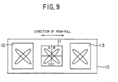
- FIG.9 is a plan view showing the general construction of he photodetector 10 shown in FIG.8 on an enlarge scale.
- those parts which are the same as those corresponding parts in FIG.6 are designated by the same reference numerals, and a description thereof will be omitted.
- cylindrical lens 27 is arranged perpendicular with respect to the optical axis, no coma aberration is generated, and it is possible to obtain an extremely stable push-pull signal.
- FIG.10 is a diagram for explaining a case where a plano concave cylindrical lens 28 is used
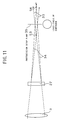
- FIG.11 is a diagram for explaining a case where the cylindrical lens 27 of the second embodiment having the concave cylindrical surfaces on both sides thereof is used.
- the illustration of the plate-shaped polarization beam splitter 2 is omitted, because the astigmatisms are mutually cancelled due to the interactions of the plate-shaped polarization beam splitter 2 and the Wollaston prism 9.
- the reflected light from the magneto-optic disk 100 is transmitted through the collimator lens 3 and is converted into convergent light.
- This convergent light is input to the plano concave cylindrical lens 28, and the astigmatism is generated.
- the plano concave cylindrical lens 28 is arranged in a direction so that the edge line of the concave cylindrical surface provided on one side of the plano concave cylindrical lens 28 is parallel to the paper in FIG.10, and for example, a convergent light (plane light) 30 on the paper is completely unaffected by the lens operation of the plano concave cylindrical lens 28.
- a convergent point S1 of the light is determined by the focal distance of the collimator lens 3 and the thickness of the plano concave cylindrical lens 28.
- the convergent light within the plane perpendicular to the paper and including the optical axis is affected by the lens operation of the plano concave cylindrical lens 28, and a convergent position shifts from the convergent point S1 to a convergent point S2 which is located farther away from the plano concave cylindrical lens 28 depending on the curvature of the concave cylindrical surface of the plano concave cylindrical lens 28.
- the light viewed in a direction parallel to the paper is indicated as a convergent light 31.
- a position where the image height of the convergent light 30 becomes the same as that of the convergent light 31 corresponds to a position 29 where the so-called least circle of confusion appears, and the photodetector 10 is arranged at this position 29.
- the reflected light from the magneto-optic disk 100 is transmitted through the collimator lens 3 and is converted into a convergent light.
- This convergent light is input to the cylindrical lens 27, and the astigmatism is generated.
- the edge lines of the two concave cylindrical surfaces on both sides of the cylindrical lens 27 are perpendicular to each other, and the curvatures of the two concave cylindrical surfaces are mutually different.
- the edge line of the concave cylindrical surface on the input side of the cylindrical lens 27 is parallel to the paper, and the edge line of the concave cylindrical surface on the output side of the cylindrical lens 27 is perpendicular to the paper.
- the radius of curvature of the concave cylindrical surface on the input side of the cylindrical lens 27 is smaller than that of the concave cylindrical surface on the output side of the cylindrical lens 27.
- a convergent light (plane light) 33 on the paper is completely unaffected by the lens operation of the input side of the cylindrical lens 27.
- the convergent light 33 is affected by the lens operation of the output side of the cylindrical lens 27, and a convergent point S3 is located at a position farther away from the cylindrical lens 27 than the convergent position which is determined by the focal distance of the collimator lens 3 and the thickness of the cylindrical lens 27.
- the convergent light within the plane perpendicular to the paper and including the optical axis is affected by the lens operation of the input side of the cylindrical lens 27, but is unaffected by the lens operation of the output side of the cylindrical lens 27.
- the radius of curvature of the concave cylindrical surface on the input side of the cylindrical lens 27 is smaller than that of the concave cylindrical surface on the output side of the cylindrical lens 27, the convergent position of the convergent light within the plane perpendicular to the paper and including the optical axis shifts to a convergent point S4 which is farther away from the cylindrical lens 27 than the convergent point S3, although it depend upon the thickness of the cylindrical lens 27.
- the light viewed in a direction parallel to the paper is indicated as a convergent light 34.
- a position where the image height of the convergent light 33 becomes the same as that of the convergent light 34 corresponds to a position 35 where the so-called least circle of confusion appears, and the photodetector 10 is arranged at this position 35.
- the magneto-optic disk is used as the recording medium, but the present invention is of course similarly applicable to other magneto-optic recording mediums.
Landscapes
- Physics & Mathematics (AREA)
- Optics & Photonics (AREA)
- Optical Head (AREA)
Applications Claiming Priority (6)
| Application Number | Priority Date | Filing Date | Title |
|---|---|---|---|
| JP272865/97 | 1997-10-06 | ||
| JP27286597 | 1997-10-06 | ||
| JP27286597 | 1997-10-06 | ||
| JP10060067A JPH11176019A (ja) | 1997-10-06 | 1998-03-11 | 光学的情報記憶装置 |
| JP60067/98 | 1998-03-11 | ||
| JP6006798 | 1998-03-11 |
Publications (2)
| Publication Number | Publication Date |
|---|---|
| EP0908879A2 true EP0908879A2 (de) | 1999-04-14 |
| EP0908879A3 EP0908879A3 (de) | 2000-02-23 |
Family
ID=26401121
Family Applications (1)
| Application Number | Title | Priority Date | Filing Date |
|---|---|---|---|
| EP98105519A Withdrawn EP0908879A3 (de) | 1997-10-06 | 1998-03-26 | Optisches Informationsspeichergerät |
Country Status (3)
| Country | Link |
|---|---|
| US (1) | US6091692A (de) |
| EP (1) | EP0908879A3 (de) |
| JP (1) | JPH11176019A (de) |
Families Citing this family (9)
| Publication number | Priority date | Publication date | Assignee | Title |
|---|---|---|---|---|
| JP2005505880A (ja) * | 2001-10-16 | 2005-02-24 | コーニンクレッカ フィリップス エレクトロニクス エヌ ヴィ | 光走査デバイス |
| JP2004079030A (ja) * | 2002-08-12 | 2004-03-11 | Sony Corp | ディスクドライブ装置、アドレス検出方法 |
| JP2005129186A (ja) * | 2003-10-27 | 2005-05-19 | Konica Minolta Opto Inc | 光ピックアップ装置 |
| JP2006079798A (ja) * | 2004-08-09 | 2006-03-23 | Sanyo Electric Co Ltd | 光ピックアップ装置 |
| JP2008065914A (ja) * | 2006-09-07 | 2008-03-21 | Nidec Sankyo Corp | 光ヘッド装置 |
| JP2012243363A (ja) * | 2011-05-20 | 2012-12-10 | Sony Corp | 再生方法、再生装置 |
| CN105340012B (zh) | 2013-06-28 | 2019-06-28 | 索尼公司 | 光学介质再现装置和光学介质再现方法 |
| EP3035332B1 (de) | 2013-08-14 | 2021-04-07 | Sony Corporation | Vorrichtung zur abspielung eines optischen mediums sowie verfahren zur abspielung eines optischen mediums |
| JP6167918B2 (ja) | 2013-08-14 | 2017-07-26 | ソニー株式会社 | 光媒体再生装置および光媒体再生方法 |
Family Cites Families (20)
| Publication number | Priority date | Publication date | Assignee | Title |
|---|---|---|---|---|
| JPS61184740A (ja) * | 1985-02-13 | 1986-08-18 | Mitsubishi Electric Corp | 光ピツクアツプ装置 |
| US5416755A (en) * | 1985-02-28 | 1995-05-16 | Canon Kabushiki Kaisha | Optical pickup using split beams impinging on different photo-detector areas |
| JPS61271633A (ja) * | 1985-05-28 | 1986-12-01 | Mitsubishi Electric Corp | 光学ヘツド装置 |
| JPS629537A (ja) * | 1985-07-08 | 1987-01-17 | Pioneer Electronic Corp | 光学式ピツクアツプ装置 |
| CA1319194C (en) * | 1986-07-28 | 1993-06-15 | Hideaki Satou | Focusing error detector and optical data detecting device incorporating the focusing error detector |
| JPS63129529A (ja) * | 1986-11-19 | 1988-06-01 | Toshiba Corp | 光学式ピツクアツプヘツド |
| JP2533872B2 (ja) * | 1987-04-10 | 1996-09-11 | 住友電気工業株式会社 | 切削工具用複合材料 |
| JPH01277711A (ja) * | 1988-04-30 | 1989-11-08 | Sharp Corp | 距離検出装置 |
| JPH05151643A (ja) * | 1991-11-29 | 1993-06-18 | Nippon Steel Corp | 光磁気検出装置 |
| US5392274A (en) * | 1991-12-20 | 1995-02-21 | Ricoh Company, Ltd. | Optical pickup device |
| JPH0668540A (ja) * | 1992-08-17 | 1994-03-11 | Sony Corp | 光学ピックアップ装置 |
| EP0602732A3 (de) * | 1992-12-17 | 1995-09-27 | Philips Electronics Nv | Optisches System mit Astigmatismuskompensation. |
| US5550798A (en) * | 1993-04-13 | 1996-08-27 | Sony Corporation | Enhanced optical beam splitter to increase the kerr rotation angle |
| JPH0750018A (ja) * | 1993-08-04 | 1995-02-21 | Hitachi Ltd | 光学ヘッドおよびそれを用いた光学情報機器 |
| JP3369666B2 (ja) * | 1993-09-22 | 2003-01-20 | 株式会社東芝 | 光学ヘッド装置 |
| US5508992A (en) * | 1993-09-29 | 1996-04-16 | Tdk Corporation | Magneto-optical recording/reproducing pickup head with a diffraction grating and a wollaston prism |
| JP3264346B2 (ja) * | 1993-12-22 | 2002-03-11 | ティーディーケイ株式会社 | 光磁気記録再生用ピックアップ装置 |
| JP3019181B2 (ja) * | 1993-12-27 | 2000-03-13 | 日本電気株式会社 | 光ヘッドのサーボ信号検出装置 |
| JP2605636B2 (ja) * | 1994-10-17 | 1997-04-30 | 日本電気株式会社 | 光ヘッドの非点隔差補正方法および装置 |
| US5933401A (en) * | 1996-06-07 | 1999-08-03 | Samsung Electronics Co., Ltd. | Optical pickup having plural optical sources and plural optical detectors |
-
1998
- 1998-03-11 JP JP10060067A patent/JPH11176019A/ja active Pending
- 1998-03-26 EP EP98105519A patent/EP0908879A3/de not_active Withdrawn
- 1998-03-27 US US09/049,796 patent/US6091692A/en not_active Expired - Fee Related
Also Published As
| Publication number | Publication date |
|---|---|
| US6091692A (en) | 2000-07-18 |
| EP0908879A3 (de) | 2000-02-23 |
| JPH11176019A (ja) | 1999-07-02 |
Similar Documents
| Publication | Publication Date | Title |
|---|---|---|
| US4797868A (en) | Optical system employing a laser beam for focusing, tracking and transferring information signals with respect to a magneto-optical memory | |
| JPS618744A (ja) | 光デイスク装置のフオ−カス誤差検出装置 | |
| JPWO1993016469A1 (ja) | 位相変化装置とそれを用いた光磁気記憶装置用光ピックアップ装置 | |
| US5570333A (en) | Head device for magneto-optical disk | |
| US5903529A (en) | Optical pickup device and disk player apparatus | |
| US6091692A (en) | Optical information storage apparatus | |
| EP1811511A2 (de) | Optisches Aufzeichnungs-/Wiedergabegerät, optischer Lesekopf und Verfahren zur Spurfehlererkennung | |
| US6167018A (en) | Optical information storage apparatus having cylindrical lens for eliminating astigmatism generated by polarization beam splitter and newly generating astigmatism | |
| JPH02230517A (ja) | 光ヘッド | |
| US5189651A (en) | Optical system in magneto-optical recording and reproducing device | |
| JPH11110811A (ja) | 光学的情報記憶装置 | |
| US4954702A (en) | Process for detecting a focal point in an optical head | |
| JPS62137736A (ja) | 光ヘツド装置 | |
| JPH07169129A (ja) | 光ヘッド | |
| US6094412A (en) | Optical information storage unit | |
| JPH0327978B2 (de) | ||
| JPS60234235A (ja) | 光学式記録再生装置 | |
| JPS62264444A (ja) | 光学式記録再生装置 | |
| EP0910070A2 (de) | Optisches Informationsaufzeichnungs/-wiedergabegerät | |
| JPH06302044A (ja) | 光ピックアップ装置 | |
| JPS60157745A (ja) | 光磁気記録装置 | |
| US5532477A (en) | Optical pickup apparatus having lens group for determining paths of an incident beam and a reflected & beam | |
| JPH0711874B2 (ja) | 光磁気信号検出装置 | |
| JPH0512747A (ja) | 光学的情報記録再生装置 | |
| US20080253261A1 (en) | Optical Pickup Having Aberration Correction |
Legal Events
| Date | Code | Title | Description |
|---|---|---|---|
| PUAI | Public reference made under article 153(3) epc to a published international application that has entered the european phase |
Free format text: ORIGINAL CODE: 0009012 |
|
| AK | Designated contracting states |
Kind code of ref document: A2 Designated state(s): AT BE CH DE DK ES FI FR GB GR IE IT LI LU MC NL PT SE |
|
| AX | Request for extension of the european patent |
Free format text: AL;LT;LV;MK;RO;SI |
|
| PUAL | Search report despatched |
Free format text: ORIGINAL CODE: 0009013 |
|
| AK | Designated contracting states |
Kind code of ref document: A3 Designated state(s): AT BE CH DE DK ES FI FR GB GR IE IT LI LU MC NL PT SE |
|
| AX | Request for extension of the european patent |
Free format text: AL;LT;LV;MK;RO;SI |
|
| AKX | Designation fees paid | ||
| 17P | Request for examination filed |
Effective date: 20000811 |
|
| RBV | Designated contracting states (corrected) |
Designated state(s): DE FR GB NL |
|
| 17Q | First examination report despatched |
Effective date: 20040805 |
|
| GRAP | Despatch of communication of intention to grant a patent |
Free format text: ORIGINAL CODE: EPIDOSNIGR1 |
|
| STAA | Information on the status of an ep patent application or granted ep patent |
Free format text: STATUS: THE APPLICATION IS DEEMED TO BE WITHDRAWN |
|
| 18D | Application deemed to be withdrawn |
Effective date: 20060419 |