EP0908997A1 - Dispositif de protection étanche pour une jonction de câbles haute tension - Google Patents
Dispositif de protection étanche pour une jonction de câbles haute tension Download PDFInfo
- Publication number
- EP0908997A1 EP0908997A1 EP98402320A EP98402320A EP0908997A1 EP 0908997 A1 EP0908997 A1 EP 0908997A1 EP 98402320 A EP98402320 A EP 98402320A EP 98402320 A EP98402320 A EP 98402320A EP 0908997 A1 EP0908997 A1 EP 0908997A1
- Authority
- EP
- European Patent Office
- Prior art keywords
- tube
- prefabricated
- protection device
- tubes
- waterproof protection
- Prior art date
- Legal status (The legal status is an assumption and is not a legal conclusion. Google has not performed a legal analysis and makes no representation as to the accuracy of the status listed.)
- Granted
Links
- RYGMFSIKBFXOCR-UHFFFAOYSA-N Copper Chemical compound [Cu] RYGMFSIKBFXOCR-UHFFFAOYSA-N 0.000 claims abstract description 25
- 229910052802 copper Inorganic materials 0.000 claims abstract description 25
- 239000010949 copper Substances 0.000 claims abstract description 25
- 229920002994 synthetic fiber Polymers 0.000 claims abstract description 9
- 229910052751 metal Inorganic materials 0.000 claims abstract description 4
- 239000002184 metal Substances 0.000 claims abstract description 4
- 238000003466 welding Methods 0.000 claims abstract description 4
- 230000001681 protective effect Effects 0.000 claims description 6
- 239000011810 insulating material Substances 0.000 claims description 4
- 238000001175 rotational moulding Methods 0.000 claims description 4
- 230000008878 coupling Effects 0.000 abstract 1
- 238000010168 coupling process Methods 0.000 abstract 1
- 238000005859 coupling reaction Methods 0.000 abstract 1
- 238000003754 machining Methods 0.000 description 3
- 238000000034 method Methods 0.000 description 3
- 239000004020 conductor Substances 0.000 description 2
- 238000006073 displacement reaction Methods 0.000 description 2
- 238000009413 insulation Methods 0.000 description 2
- 239000000463 material Substances 0.000 description 2
- 229910000838 Al alloy Inorganic materials 0.000 description 1
- 229910001369 Brass Inorganic materials 0.000 description 1
- 229910000906 Bronze Inorganic materials 0.000 description 1
- 229910052782 aluminium Inorganic materials 0.000 description 1
- XAGFODPZIPBFFR-UHFFFAOYSA-N aluminium Chemical compound [Al] XAGFODPZIPBFFR-UHFFFAOYSA-N 0.000 description 1
- 238000007664 blowing Methods 0.000 description 1
- 239000010951 brass Substances 0.000 description 1
- 239000010974 bronze Substances 0.000 description 1
- KUNSUQLRTQLHQQ-UHFFFAOYSA-N copper tin Chemical compound [Cu].[Sn] KUNSUQLRTQLHQQ-UHFFFAOYSA-N 0.000 description 1
- 239000000835 fiber Substances 0.000 description 1
- 239000011521 glass Substances 0.000 description 1
- 238000000465 moulding Methods 0.000 description 1
- 238000009417 prefabrication Methods 0.000 description 1
- 239000011347 resin Substances 0.000 description 1
- 229920005989 resin Polymers 0.000 description 1
- 238000005476 soldering Methods 0.000 description 1
- 230000000007 visual effect Effects 0.000 description 1
- 238000004804 winding Methods 0.000 description 1
Images



Classifications
-
- H—ELECTRICITY
- H02—GENERATION; CONVERSION OR DISTRIBUTION OF ELECTRIC POWER
- H02G—INSTALLATION OF ELECTRIC CABLES OR LINES, OR OF COMBINED OPTICAL AND ELECTRIC CABLES OR LINES
- H02G15/00—Cable fittings
- H02G15/08—Cable junctions
- H02G15/10—Cable junctions protected by boxes, e.g. by distribution, connection or junction boxes
- H02G15/115—Boxes split perpendicularly to main cable direction
-
- H—ELECTRICITY
- H02—GENERATION; CONVERSION OR DISTRIBUTION OF ELECTRIC POWER
- H02G—INSTALLATION OF ELECTRIC CABLES OR LINES, OR OF COMBINED OPTICAL AND ELECTRIC CABLES OR LINES
- H02G15/00—Cable fittings
- H02G15/08—Cable junctions
- H02G15/10—Cable junctions protected by boxes, e.g. by distribution, connection or junction boxes
- H02G15/103—Cable junctions protected by boxes, e.g. by distribution, connection or junction boxes with devices for relieving electrical stress
Definitions
- the present invention relates to a waterproof protection device for a joining high-voltage cables, comprising at least one tubular structure metallic and at least one external insulating sheath
- protective devices of this type comprising envelopes made of many parts that the operator must assemble at the place of cable mounting. These parts include copper or lead tubes that the operator must weld or screw together brass, bronze or insulating material, O-rings or flat seals, epoxy-fiber resin housings glass, connection hardware, hardware, heat shrink tubing, putty and a large quantity of filling material to be poured on site.
- the present invention proposes to remedy these various drawbacks by providing a protection device for joining high-voltage cables, consisting of a minimum of elements, which are entirely prefabricated in the factory.
- the waterproof protection device comprising a metallic tubular structure and an outer insulating sheath is characterized by what it consists of a first and a second prefabricated element, having a sealed connection zone to each other and each comprising at least one first tube and an outer preformed envelope integral with each tube of this same prefabricated element, the tubes of said prefabricated elements assembled together constituting said metallic tubular structure and their envelopes respective preforms being tightly coupled to each other in said connection zone and thus constituting said outer insulating sheath.
- the first tube of one of said prefabricated elements has a flare at one of its ends, allowing its nesting on one end of the first tube of the other prefabricated element and the welding of these nested ends.
- the tubes are advantageously made of copper and made with rolled and welded copper sheet.
- the preformed envelopes are preferably adapted to the profile of the tubes respective and are made of synthetic material by rotational molding.
- the two preformed envelopes are coupled by means of an insert which covers the welded connection zone of the tubes and which is tightly linked respectively to the two envelopes.
- said first tube is unique in each of said prefabricated elements and comprises two cylindrical sections opposite joined by a conical section between them, said connection zone said prefabricated elements being terminal on the cylindrical section further large diameter of the first tube of each of them.
- one of the cylindrical sections is of diameter adapted to that of a cable to be connected, and the other cylindrical section is adapted to diameter of a junction body.
- the first tube of said first prefabricated element is unique therein and has two circular cylindrical sections of different diameter from one another and a section conical between them, and the second prefabricated element comprises said first tube of it and a second tube, both cylindrical but of different diameter from each other, mounted substantially one after the other, isolated from each other and both carrying said preformed envelope of this second element prefabricated.
- said first and said second tube of said second prefabricated element have two opposite ends, each having a conical extension of the same angle and provide space between them.
- the space between the two metal tubes of the second element is preferably filled with an insulating material.
- the two tubes are respectively associated with means of connection to external local grounding cables from each or swapping screens.
- the device for waterproof protection for a high voltage cable junction 10 consists mainly of two elements 11 and 12 which are respectively mounted on two cables 13 and 14 which are provided for junction by means of a junction body prefabricated which is neither shown nor described, as it is not part of this invention.
- the two elements 11 and 12 are assembled in a sealed manner according to a process which will be described later.
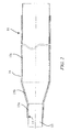
- Element 11 is shown enlarged by Figure 2. It consists mainly a copper tube 15 and a protective envelope 16 made of an insulating synthetic material, which at least partially covers the tube made of copper 15.
- This tube 15 is made up of a cylindrical section 15a circular, of a length such as to cover and protect the part of the cable that it was necessary to strip for its parking during the operation for connecting the conductors in the prefabricated junction body.
- the diameter of this part is adapted to the diameter of the cable 13.
- This part is extended by a second conical part 15b and by a third circular cylindrical part 15c of diameter greater than that of the first part 15a and which adapts to the outside diameter of the junction body.
- the copper tube 15 is preferably manufactured using copper sheets rolled and welded or in the form of a tubular part shaped by a any suitable machining process.
- the protective envelope 16 is preferably manufactured according to a process rotational molding, however, other methods such as in particular molding by blowing could, if necessary, be used.
- the envelope 16 is slid to hot on the copper tube 15, which ensures sufficient tightening for that it no longer moves relative to this tube, even when it heats up at the maximum service temperature of the junction.
- the total length of the element 11 is adapted to the length of the element 12 and the two elements which constitute the protective device have a length adapted to that of the junction body.
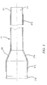
- Element 12 consists of a copper tube and an envelope of protection 18, made of an insulating synthetic material, which partially covers the copper tube 17.
- This tube includes, like element 11, a part circular cylindrical 17a which has a diameter equivalent to that of the cable 14, a conical part 17b which extends part 17a, and a circular cylindrical part 17c which extends the conical part 17b.
- the cylindrical part 17c has a flaring 17d at its free end, which allows interlocking with respect to the free end of the cylindrical part of enlarged diameter 15c of the element 11.
- the copper tube 17 of element 12 is covered with a protective envelope 18, preferably made by rotational molding which adapts to the profile of the copper tube 17 which it encloses so as to prevent any relative displacement between it and this tube, even at the maximum service temperature of the junction.
- the copper tube can be manufactured by forming or machining or by winding of sheets which are then welded.
- the two elements are assembled and connected by fitting of the two copper tubes 15 and 17 at the flaring 17d, followed by a soldering of these two copper tubes.
- the tight connection of two insulating envelopes 16 and 18 is preferably carried out by means of a piece reported 19 which provides a bridge over the weld zone of the two copper tubes 15 and 17. This part is preferably heat-welded to the two insulating envelopes. However, it could also be glued or reconstituted on site, using suitable synthetic materials.
- FIG. 4 illustrates an alternative embodiment of a protection device waterproof of a high voltage cable junction.
- the device 20 mainly comprises two elements 21 and 22 assembled and mounted respectively on the two cables 13 and 14 whose junction is made by means a junction body (not shown).
- the element 21 is identical to element 11 described above.
- element 22 differs from element 12. It is represented enlarged by FIG. 5.
- This element 22 comprises two cylindrical copper tubes 23 and 24, insulated from each other by a layer of molded synthetic material 25. These tubes are connected to one or two cables external by means of connection incorporated into the element, for putting them to a local ground or a permutation of screens.
- the first tube 23 has a diameter adapted to the outside diameter of the cable 14 to be connected and its length is such that the protection of the part of the cable that it is necessary to strip for its parking during the connection operation of the conductors, be ensured.
- This tube is provided at one end with an open conical extension 26. It is further equipped with connection means 27 for one or two cables 28. These connection means consist, for example, of a screw clamp 27a and a cable clamp device 27b known per se. These means of connection could also consist of a weld.
- the second tube 24 has a diameter adapted to that of the junction body, which is greater than that of cable 14.
- One of its ends is terminated by a flare 29 intended to cooperate with the end of the copper tube of the element 21 to ensure a superposition and a welding of the two tubes.
- the other end is extends by a conical part 30 directed towards the axis of the device, the angle of which is identical to that of the open conical extension 26 of the first tube 23. It also comprises a means of connection to an external cable 31, of the type cable clamp or similar, for connection to local ground or swap screens.
- the two conical parts 26 and 30 of the two tubes 23 and 24 overlap.
- the tubes 23 and 24 are preferably manufactured in by means of rolled and welded sheets, but could also be made by machining or any other appropriate means.
- the tubes are covered, at least partially, by an envelope insulating material 32 of synthetic material, preferably rotomolded. As previously, it is advantageously slid hot over the copper tubes so that it ensures sufficient tightening to avoid any relative displacement.
- the envelope constitutes the mold for the insulating filling material, which constitutes the layer of molded synthetic material 25 and also protects the screen connection system.
- a reconstituted insulation which can consist of a heat-sealed insert 33 the two insulating envelopes associated with the two copper tubes.
- This insulation can also be constituted by a tape of putty and / or a heat-shrinkable sleeve.
- metal tubes is not necessarily limited to two and the cylindrical and conical sections of a tube could for example be embedded in an insulating mass.
- These tubes could also be made of aluminum or aluminum alloys.
Landscapes
- Cable Accessories (AREA)
- Processing Of Terminals (AREA)
Abstract
Description
- la figure 1 est une vue d'ensemble d'une première forme de réalisation du dispositif de protection étanche d'une jonction de câbles haute tension selon l'invention,
- la figure 2 est une vue en coupe agrandie du premier élément du dispositif selon la figure 1,
- la figure 3 est une vue en coupe agrandie du deuxième élément du dispositif selon la figure 1,
- la figure 4 est une vue d'ensemble d'une seconde forme de réalisation du dispositif de protection étanche d'une jonction de câbles haute tension selon l'invention, et
- la figure 5 est une vue en coupe agrandie du deuxième élément du dispositif selon la figure 4.
Claims (11)
- Dispositif de protection étanche pour une jonction de câbles haute tension, comportant une structure tubulaire métallique et une gaine isolante extérieure, caractérisé en ce qu'il est constitué par un premier et un deuxième élément préfabriqué (11, 12; 21, 22) présentant une zone de raccordement étanche l'un à l'autre et comportant chacun au moins un premier tube (15; 17; 24) et une enveloppe préformée extérieure (16; 18; 32) solidaire de chaque tube de ce même élément préfabriqué, les tubes desdits éléments préfabriqués assemblés constituant ensemble ladite structure tubulaire métallique et leurs enveloppes préformées respectives étant couplées de façon étanche l'une à l'autre dans ladite zone de raccordement et constituant ainsi ladite gaine isolante extérieure.
- Dispositif de protection étanche selon la revendication 1, caractérisé en ce que ledit premier tube (17, 24) de l'un desdits éléments préfabriqués (12, 22) comporte un évasement (17d, 29) à l'une de ses extrémités, permettant son emboítement sur l'une des extrémités dudit premier tube (15) de l'autre desdits éléments préfabriqués (11, 21) et la soudure de ces extrémités ainsi emboítées, dans ladite zone de raccordement.
- Dispositif de protection étanche selon la revendication 1, caractérisé en ce que les tubes (15, 17; 15, 23 et 24) sont en cuivre et réalisés avec de la tôle de cuivre roulée et soudée.
- Dispositif de protection étanche selon la revendication 1, caractérisé en ce que les enveloppes préformées (16, 18; 16, 32) sont adaptées au profil des tubes respectifs (15, 17; 15, 23 et 24) et sont réalisées en matière synthétique par rotomoulage.
- Dispositif de protection étanche selon la revendication 1, caractérisé en ce que les deux enveloppes préformées (16, 18; 16, 32) sont couplées au moyen d'une pièce rapportée (19, 33), qui recouvre la zone de raccordement desdits premiers tubes (15, 17; 15, 24) et qui est liée de façon étanche respectivement aux deux enveloppes.
- Dispositif de protection étanche selon la revendication 1, caractérisé en ce que ledit premier tube (15, 17) est unique dans chacun desdits éléments préfabriqués (11; 12, 21) et comporte deux tronçons cylindriques opposés réunis par un tronçon conique entre eux, ladite zone de raccordement desdits éléments préfabriqués étant terminale sur le tronçon cylindrique de plus grand diamètre du premier tube de chacun d'eux.
- Dispositif de protection étanche selon la revendication 6, caractérisé en ce que les deux tronçons cylindriques du premier tube (15, 17) de chacun desdits éléments préfabriqués ont des longueurs différentes l'un de l'autre et de l'un desdits éléments préfabriqués à l'autre.
- Dispositif de protection étanche selon la revendication 1, caractérisé en ce que le premier tube (17) dudit premier élément préfabriqué (11; 21) est unique dans celui-ci et présente deux tronçons cylindriques circulaires (17a, 17c) de diamètre différent l'un de l'autre et un tronçon conique (17b) entre eux, et le deuxième élément préfabriqué (22) comporte ledit premier tube (24) de celui-ci et un deuxième tube (23), tous deux cylindriques mais de diamètre différent l'un de l'autre, montés sensiblement à la suite l'un de l'autre, isolés l'un de l'autre et portant tous deux ladite enveloppe préformée (32) de ce deuxième élément préfabriqué.
- Dispositif de protection étanche selon la revendication 8, caractérisé en ce que ledit premier et ledit deuxième tubes (24, 23) dudit deuxième élément préfabriqué (22) ont deux extrémités en vis-à-vis, présentant chacune un prolongement conique (26, 30) de même angle et ménageant un espace entre elles.
- Dispositif de protection étanche selon la revendication 9, caractérisé en ce que l'espace entre lesdits premier et deuxième tubes (23, 24) du deuxième élément (22) est rempli par un matériau isolant.
- Dispositif de protection étanche selon l'une des revendications 8 à 10, caractérisé en ce que lesdits premier et deuxième tubes (23, 24) dudit deuxième élément préfabriqué (22) sont respectivement associés à des moyens de raccordement (27, 31) de câbles extérieurs pour une mise à une terre locale de chacun d'eux ou une permutation d'écrans.
Applications Claiming Priority (2)
| Application Number | Priority Date | Filing Date | Title |
|---|---|---|---|
| FR9712511 | 1997-10-07 | ||
| FR9712511A FR2769419B1 (fr) | 1997-10-07 | 1997-10-07 | Dispositif de protection etanche pour une jonction de cables haute tension |
Publications (2)
| Publication Number | Publication Date |
|---|---|
| EP0908997A1 true EP0908997A1 (fr) | 1999-04-14 |
| EP0908997B1 EP0908997B1 (fr) | 2006-12-13 |
Family
ID=9511937
Family Applications (1)
| Application Number | Title | Priority Date | Filing Date |
|---|---|---|---|
| EP98402320A Expired - Lifetime EP0908997B1 (fr) | 1997-10-07 | 1998-09-21 | Dispositif de protection étanche pour une jonction de câbles haute tension |
Country Status (7)
| Country | Link |
|---|---|
| US (1) | US6172304B1 (fr) |
| EP (1) | EP0908997B1 (fr) |
| JP (1) | JPH11191910A (fr) |
| CN (1) | CN1144338C (fr) |
| CA (1) | CA2246651C (fr) |
| DE (1) | DE69836611T2 (fr) |
| FR (1) | FR2769419B1 (fr) |
Families Citing this family (12)
| Publication number | Priority date | Publication date | Assignee | Title |
|---|---|---|---|---|
| US6919512B2 (en) * | 2001-10-03 | 2005-07-19 | Schlumberger Technology Corporation | Field weldable connections |
| KR101135143B1 (ko) * | 2004-03-01 | 2012-04-16 | 후루카와 덴키 고교 가부시키가이샤 | 케이블 접속구조 |
| SE531433C2 (sv) * | 2007-08-28 | 2009-04-07 | Abb Technology Ag | Anordning för att expandera en rörformig elastisk kropp |
| EP2088657A1 (fr) | 2008-02-08 | 2009-08-12 | ABB Technology AG | Procédé de production d'une enveloppe de câble, enveloppe de câble et agencement de joint de câble fourni avec celui-ci |
| EP2088656A1 (fr) * | 2008-02-08 | 2009-08-12 | ABB Technology AG | Agencement de joint de câble |
| EP2113978B1 (fr) | 2008-04-30 | 2012-06-06 | ABB Technology Ltd | Boîtier de protection pour câble haute tension |
| US8872025B2 (en) * | 2011-03-16 | 2014-10-28 | Jtekt Corporation | Waterproof structure of electronic unit |
| CN103986112B (zh) * | 2013-02-12 | 2017-03-01 | 株式会社维世佳 | 电力电缆的连接构造和绝缘部件 |
| CN104716606B (zh) * | 2013-12-17 | 2017-02-15 | 国家电网公司 | 电缆线头保护装置 |
| JP2016010202A (ja) * | 2014-06-23 | 2016-01-18 | 株式会社ビスキャス | 電力ケーブル接続部および防食カバー |
| JP6164257B2 (ja) * | 2015-07-10 | 2017-07-19 | 株式会社オートネットワーク技術研究所 | モールド部付電線及びモールド部付電線製造方法 |
| CN111697404B (zh) * | 2020-05-23 | 2021-07-23 | 国家电网有限公司 | 高压电缆锡纸接地引线冷连接法 |
Citations (6)
| Publication number | Priority date | Publication date | Assignee | Title |
|---|---|---|---|---|
| US1723846A (en) * | 1925-03-10 | 1929-08-06 | Gen Electric | Insulated cable joint |
| DE1465809A1 (de) * | 1964-10-28 | 1969-05-29 | Rheydt Kabelwerk Ag | Quernahtmetallmuffe fuer elektrische Kabel aus zwei ineinandergesteckten und miteinander verloeteten Rohrstuecken |
| US4110550A (en) * | 1976-11-01 | 1978-08-29 | Amerace Corporation | Electrical connector with adaptor for paper-insulated, lead-jacketed electrical cables and method |
| EP0225784A2 (fr) * | 1985-12-09 | 1987-06-16 | Amerace Corporation | Dispositif de protection d'une jonction de câbles haute tension |
| EP0475561A1 (fr) * | 1990-09-13 | 1992-03-18 | The Furukawa Electric Co., Ltd. | Câbles électriques isolés par du caoutchouc ou du plastique et une jonction de ces câbles et méthode pour sa fabrication |
| EP0780949A1 (fr) * | 1995-12-23 | 1997-06-25 | Minnesota Mining And Manufacturing Company | Adaptateur de câble universel, jonction de câble utilisant l'adaptateur et procédé de fabrication de celui-ci |
Family Cites Families (7)
| Publication number | Priority date | Publication date | Assignee | Title |
|---|---|---|---|---|
| US4580874A (en) * | 1983-06-27 | 1986-04-08 | Olin Corporation | Optical fiber cable repair and joining technique and kit for performing the same |
| GB8526377D0 (en) * | 1985-10-25 | 1985-11-27 | Raychem Gmbh | Cable connection |
| JP2514369B2 (ja) | 1986-07-31 | 1996-07-10 | コニカ株式会社 | 迅速処理性に優れた色素画像の形成方法 |
| CA1302531C (fr) * | 1987-04-06 | 1992-06-02 | N.V. Raychem S.A. | Gaine pour epissures |
| GB9414039D0 (en) * | 1994-07-11 | 1994-09-28 | Raychem Ltd | Electrical interconnection |
| US5661842A (en) * | 1995-05-26 | 1997-08-26 | At&T | Method for providing submarine cable joint protection and insulation using heat shrink tubing |
| US5844170A (en) * | 1996-03-01 | 1998-12-01 | Minnesota Mining And Manufacturing Company | Closure with flowable material and reinforcing core |
-
1997
- 1997-10-07 FR FR9712511A patent/FR2769419B1/fr not_active Expired - Fee Related
-
1998
- 1998-09-21 DE DE69836611T patent/DE69836611T2/de not_active Expired - Lifetime
- 1998-09-21 EP EP98402320A patent/EP0908997B1/fr not_active Expired - Lifetime
- 1998-10-05 JP JP10282506A patent/JPH11191910A/ja not_active Withdrawn
- 1998-10-06 CA CA002246651A patent/CA2246651C/fr not_active Expired - Fee Related
- 1998-10-06 US US09/166,795 patent/US6172304B1/en not_active Expired - Lifetime
- 1998-10-07 CN CNB981246265A patent/CN1144338C/zh not_active Expired - Fee Related
Patent Citations (6)
| Publication number | Priority date | Publication date | Assignee | Title |
|---|---|---|---|---|
| US1723846A (en) * | 1925-03-10 | 1929-08-06 | Gen Electric | Insulated cable joint |
| DE1465809A1 (de) * | 1964-10-28 | 1969-05-29 | Rheydt Kabelwerk Ag | Quernahtmetallmuffe fuer elektrische Kabel aus zwei ineinandergesteckten und miteinander verloeteten Rohrstuecken |
| US4110550A (en) * | 1976-11-01 | 1978-08-29 | Amerace Corporation | Electrical connector with adaptor for paper-insulated, lead-jacketed electrical cables and method |
| EP0225784A2 (fr) * | 1985-12-09 | 1987-06-16 | Amerace Corporation | Dispositif de protection d'une jonction de câbles haute tension |
| EP0475561A1 (fr) * | 1990-09-13 | 1992-03-18 | The Furukawa Electric Co., Ltd. | Câbles électriques isolés par du caoutchouc ou du plastique et une jonction de ces câbles et méthode pour sa fabrication |
| EP0780949A1 (fr) * | 1995-12-23 | 1997-06-25 | Minnesota Mining And Manufacturing Company | Adaptateur de câble universel, jonction de câble utilisant l'adaptateur et procédé de fabrication de celui-ci |
Also Published As
| Publication number | Publication date |
|---|---|
| FR2769419B1 (fr) | 2003-05-23 |
| FR2769419A1 (fr) | 1999-04-09 |
| DE69836611T2 (de) | 2007-10-25 |
| DE69836611D1 (de) | 2007-01-25 |
| CN1144338C (zh) | 2004-03-31 |
| CA2246651A1 (fr) | 1999-04-07 |
| CA2246651C (fr) | 2002-12-10 |
| EP0908997B1 (fr) | 2006-12-13 |
| US6172304B1 (en) | 2001-01-09 |
| JPH11191910A (ja) | 1999-07-13 |
| CN1221999A (zh) | 1999-07-07 |
Similar Documents
| Publication | Publication Date | Title |
|---|---|---|
| CA2246651C (fr) | Dispositif de protection etanche pour une jonction de cables haute tension | |
| EP0383671B1 (fr) | Système détecteur d'obstacle comprenant un ensemble de connexion perfectionné | |
| EP0234161B1 (fr) | Dispositif pour relier deux câbles électriques isolés comportant des moyens perfectionnés de protection extérieure de la jonction | |
| WO2018069651A1 (fr) | Systeme sous-marin de raccordement electrique | |
| WO2014176706A1 (fr) | Procede de fabrication d'un cable chauffant et cable chauffant realise selon ce procede | |
| FR2716521A1 (fr) | Raccord angulaire. | |
| EP0595708A1 (fr) | Dispositif anti-retrait d'isolation, pour cable de puissance à isolation synthétique | |
| EP0552082A1 (fr) | Protection de terminaison de câble moyenne tension | |
| EP2038978A1 (fr) | Structure de traversee electrique pour element supraconducteur | |
| FR3022406A1 (fr) | Organe de raccordement electrique pour circuit electrique de vehicule | |
| EP0512486A1 (fr) | Câble d'accès de répéteur sous-marin | |
| EP0016340B1 (fr) | Dispositif de raccordement entre les conducteurs extérieurs de deux paires coaxiales | |
| EP1337018A1 (fr) | Traversée de courant sous enveloppe metallique étanche au gaz | |
| EP0862801B1 (fr) | Piece de raccordement electrique | |
| EP1018756B1 (fr) | Dispositif de coupure électrique pour moyenne et haute tension | |
| FR2493057A1 (fr) | Dispositif de raccordement electrique etanche entre un cable sous-marin telephonique et un repeteur | |
| EP0683556B1 (fr) | Pièce de liaison électrique d'un manchon protecteur avec une extrémité d'un écran semi-conducteur d'un câble électrique | |
| FR2505569A1 (fr) | Jonction multiple pour systeme sous-marin | |
| FR2783915A1 (fr) | Transducteur ultrasonore | |
| FR2797108A1 (fr) | Ligne electrique haute tension, a isolation gazeuse, module de raccordement entre troncons successifs constituant une telle ligne et procede de montage correspondant | |
| FR2689302A1 (fr) | Structure de scellement de deux éléments par fusion d'un corps intermédiaire et notamment application à la traversée d'un élément de condensateur. | |
| FR2638574A1 (fr) | Procede et dispositif de liaison coaxiale hyperfrequence | |
| EP1009002A1 (fr) | Dispositif de coupure électrique pour moyenne et haute tension | |
| FR2752106A1 (fr) | Extremite auto-porteuse de cable d'energie | |
| EP0278844A1 (fr) | Câble électrique, notamment isolé au papier imprégné, à l'extrémité duquel est rapporté un dispositif de raccordement |
Legal Events
| Date | Code | Title | Description |
|---|---|---|---|
| PUAI | Public reference made under article 153(3) epc to a published international application that has entered the european phase |
Free format text: ORIGINAL CODE: 0009012 |
|
| AK | Designated contracting states |
Kind code of ref document: A1 Designated state(s): CH DE GB IT LI NL SE |
|
| AX | Request for extension of the european patent |
Free format text: AL;LT;LV;MK;RO;SI |
|
| 17P | Request for examination filed |
Effective date: 19991014 |
|
| AKX | Designation fees paid |
Free format text: CH DE GB IT LI NL SE |
|
| RAP1 | Party data changed (applicant data changed or rights of an application transferred) |
Owner name: NEXANS |
|
| GRAP | Despatch of communication of intention to grant a patent |
Free format text: ORIGINAL CODE: EPIDOSNIGR1 |
|
| GRAS | Grant fee paid |
Free format text: ORIGINAL CODE: EPIDOSNIGR3 |
|
| GRAA | (expected) grant |
Free format text: ORIGINAL CODE: 0009210 |
|
| AK | Designated contracting states |
Kind code of ref document: B1 Designated state(s): CH DE GB IT LI NL SE |
|
| REG | Reference to a national code |
Ref country code: GB Ref legal event code: FG4D Free format text: NOT ENGLISH |
|
| REG | Reference to a national code |
Ref country code: CH Ref legal event code: EP |
|
| REF | Corresponds to: |
Ref document number: 69836611 Country of ref document: DE Date of ref document: 20070125 Kind code of ref document: P |
|
| REG | Reference to a national code |
Ref country code: CH Ref legal event code: NV Representative=s name: CRONIN INTELLECTUAL PROPERTY |
|
| PG25 | Lapsed in a contracting state [announced via postgrant information from national office to epo] |
Ref country code: SE Free format text: LAPSE BECAUSE OF FAILURE TO SUBMIT A TRANSLATION OF THE DESCRIPTION OR TO PAY THE FEE WITHIN THE PRESCRIBED TIME-LIMIT Effective date: 20070313 |
|
| REG | Reference to a national code |
Ref country code: CH Ref legal event code: PCAR Free format text: CRONIN INTELLECTUAL PROPERTY;CHEMIN DE PRECOSSY 31;1260 NYON (CH) |
|
| GBV | Gb: ep patent (uk) treated as always having been void in accordance with gb section 77(7)/1977 [no translation filed] |
Effective date: 20061213 |
|
| PLBE | No opposition filed within time limit |
Free format text: ORIGINAL CODE: 0009261 |
|
| STAA | Information on the status of an ep patent application or granted ep patent |
Free format text: STATUS: NO OPPOSITION FILED WITHIN TIME LIMIT |
|
| 26N | No opposition filed |
Effective date: 20070914 |
|
| PG25 | Lapsed in a contracting state [announced via postgrant information from national office to epo] |
Ref country code: GB Free format text: LAPSE BECAUSE OF FAILURE TO SUBMIT A TRANSLATION OF THE DESCRIPTION OR TO PAY THE FEE WITHIN THE PRESCRIBED TIME-LIMIT Effective date: 20061213 |
|
| PGFP | Annual fee paid to national office [announced via postgrant information from national office to epo] |
Ref country code: NL Payment date: 20080915 Year of fee payment: 11 |
|
| REG | Reference to a national code |
Ref country code: NL Ref legal event code: V1 Effective date: 20100401 |
|
| PG25 | Lapsed in a contracting state [announced via postgrant information from national office to epo] |
Ref country code: NL Free format text: LAPSE BECAUSE OF NON-PAYMENT OF DUE FEES Effective date: 20100401 |
|
| PGFP | Annual fee paid to national office [announced via postgrant information from national office to epo] |
Ref country code: CH Payment date: 20110923 Year of fee payment: 14 |
|
| REG | Reference to a national code |
Ref country code: CH Ref legal event code: PL |
|
| PG25 | Lapsed in a contracting state [announced via postgrant information from national office to epo] |
Ref country code: LI Free format text: LAPSE BECAUSE OF NON-PAYMENT OF DUE FEES Effective date: 20130930 Ref country code: CH Free format text: LAPSE BECAUSE OF NON-PAYMENT OF DUE FEES Effective date: 20130930 |
|
| PGFP | Annual fee paid to national office [announced via postgrant information from national office to epo] |
Ref country code: DE Payment date: 20140922 Year of fee payment: 17 |
|
| PGFP | Annual fee paid to national office [announced via postgrant information from national office to epo] |
Ref country code: IT Payment date: 20150924 Year of fee payment: 18 |
|
| REG | Reference to a national code |
Ref country code: DE Ref legal event code: R119 Ref document number: 69836611 Country of ref document: DE |
|
| PG25 | Lapsed in a contracting state [announced via postgrant information from national office to epo] |
Ref country code: DE Free format text: LAPSE BECAUSE OF NON-PAYMENT OF DUE FEES Effective date: 20160401 |
|
| PG25 | Lapsed in a contracting state [announced via postgrant information from national office to epo] |
Ref country code: IT Free format text: LAPSE BECAUSE OF NON-PAYMENT OF DUE FEES Effective date: 20160921 |