EP0909647A2 - Console de commande pour une machine à imprimer - Google Patents
Console de commande pour une machine à imprimer Download PDFInfo
- Publication number
- EP0909647A2 EP0909647A2 EP98115979A EP98115979A EP0909647A2 EP 0909647 A2 EP0909647 A2 EP 0909647A2 EP 98115979 A EP98115979 A EP 98115979A EP 98115979 A EP98115979 A EP 98115979A EP 0909647 A2 EP0909647 A2 EP 0909647A2
- Authority
- EP
- European Patent Office
- Prior art keywords
- printing
- control panel
- control
- panel according
- form production
- Prior art date
- Legal status (The legal status is an assumption and is not a legal conclusion. Google has not performed a legal analysis and makes no representation as to the accuracy of the status listed.)
- Granted
Links
Images
Classifications
-
- B—PERFORMING OPERATIONS; TRANSPORTING
- B41—PRINTING; LINING MACHINES; TYPEWRITERS; STAMPS
- B41F—PRINTING MACHINES OR PRESSES
- B41F33/00—Indicating, counting, warning, control or safety devices
Definitions
- the invention relates to a control panel for a printing press.
- Control and display elements to be structurally combined with the printing press.
- Printing presses with a substantial range of functions are usually one or provided several control desks.
- An easy-to-use control panel is table-shaped constructed, with input and display elements at working height.
- Storage areas can be provided and additional holders for a vertical arrangement of the Copies.
- the connection and power supply are in the form of inputs and outputs on the control panel provided by plugs, couplings and the like.
- At printers with one Printer control system are provided in the control panel computing means that can be connected to a computer network of the print shop.
- the object of the invention is to develop a control panel that takes up little space and low material and cost expenditure combines a multitude of functions, whereby the influence of external disturbing variables is reduced.
- the task is solved with a control panel that has the characteristics of Claim 1 has.
- the device for printing form production can be a device for in the control panel Production of a test print can be integrated.
- the computing means used for control can be connected to a network of a Printing company be connected, with circulation-related data on the customer, on Number of copies, the type of paper used and the completion date from a computer the production control can be transferred to a control computer in the control panel can. Likewise, data used to illustrate the printing forms and for Presetting of the printing press are required by a computer Prepress to be transferred.
- Aid facilities such as e.g. B. job bags, storage containers and data cartridges can be omitted.
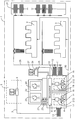
- FIG. 1 In the drawing is schematically a printing house 1 with two printing machines 2, 3, a control panel 4 and a prepress department 5 shown.
- a Layout computer 6 of the prepress department 5 is connected to a network 7 Control unit 8 connected.
- the control unit 8 contains at least hardware for one Computer, digital storage elements, a program system for realizing several Functions and interfaces or components for input and output of data or Signals.
- At the control panel 4 are an input point 9 and two output points 10, 11 for Pressure plates 12 are provided.
- the printing plates 12 for one print image each are located each in dustproof cassettes 13.
- a device 14 for printing form production and an image recording arrangement 15 installed.
- the Device 14 contains a processing table 16 for a printing plate 12, which in three Coordinate directions can be positioned. On one on the processing table 16 held printing plate 12, a laser 17 can be focused, with the energy in focus is sufficient to generate 12 pixels on the surface of the printing plates.
- the Image recording arrangement 15 contains a camera 18, with an imaged printing plate 12 using a measuring table 19 for scanning the camera 18 in at least two Directions can be positioned.
- control panel 4 for simultaneous imaging of multiple printing plates 12 multiple devices 14 for Printing form production can be provided. It is also possible within the Control panel 4, the device 14 for printing form production and Image recording arrangement 5 structurally to combine, so that the processing table 16th at the same time the measuring table 19.
- the handling of the pressure plate 12 within the Control panel 4 can be done so that the purpose of an entrance control not illustrated printing plate 12 of the image recording arrangement 15 is supplied, then the Device 14 for printing form production and then the image recording arrangement 14 is fed again for a final inspection.
- the one used for handling Conveying device can the pressure plates 12 in straight guides or on circular paths transport.
- Control elements 20 and display elements 21 are also provided on the control panel 4.
- a holder 22 for a test specimen 23 and for a OK copy 24 On a console 25 connected to the control panel 4 is a Computer 26 with a monitor 27.
- the control panel 4 is also available via a conveyor system 28 the printing presses 2, 3 and a storage system 29 in connection. Furthermore, that is Control panel 4 connected to printing presses 2, 3 via control lines 30.
- the control panel 4 serves to control at least one of the printing presses 2, 3 as well as the control of the methods for imaging the printing plate 12 and the Obtaining image signals with the aid of the image recording arrangement 15.
- the image data one generated on the layout computer 6 in the prepress department 5 Print images are transmitted to the computer of the control unit 8 via the network 7.
- Printing forms 12 can be preconditioned in the cassette 13. B. on brought to a certain temperature or in a certain humidity being held. While a printing plate 12 is being conveyed from the input point 9
- the processing table 16 can be followed by further processing steps for a Preparation for imaging is required. An example is cleaning and a coating of the printing plates 12 to be imaged.
- the illustration of the Printing plate 16 occurs pixel by pixel, with the processing table 16 positioning steps executes that perpendicular to the optical axis of the radiation emanating from the laser 17 lies.
- the pressure plate 12 can additionally in the direction of optical axis.
- the laser 17 is in accordance with the image data modulated.
- the image data originating from the computer 6 in the Control unit 8 to be processed for imaging data.
- pixels are generated on the surface of the printing plates. are ink-repellent.
- a printing plate 12 which is on the measuring table 19, with the help of the camera 18 the surface reproducing image data are obtained and fed to the control unit 8.
- the control unit 8 contains computing means for image analysis and pixel by pixel Target-actual comparison, which enables quality control of the imaging.
- the Image data of a set of printing plates 12 belonging to a print image can be the Computer 26 are supplied, the program for generating a print image contains the monitor 27.
- the operator of the printing press 2, 3 has the possibility visually check whether the printing plates 12 are correctly imaged.
- a can be sent to the control panel 4 Device for generating a test print connected or in the Control panel 4 can be integrated.
- the printing plates 12 belonging to a printed image are subjected to quality control stored in cassettes 13, which for further transport of the printing plates 12 to the Printing machines 2, 3 are docked at the issuing points 10, 11.
- a conveyor system 28 is provided for further transport.
- the cassettes 13 with the printing plates 12 are via guide rails depending on the scheduling to the printing units of the printing presses 2, 3 or promoted to the storage systems 29.
- an intermediate storage for printing plates 12 If a job is to be printed repeatedly, the sentence belonging to the job can be used can be fetched from the storage system 29 on pressure plates 12.
- the printing plates 12 for an order become an automatic system Plate feed to the respective printing unit of the printing presses 2, 3, where they are in the preparation phase for printing onto the respective printing form cylinders become.
- the image data from the computer 6 and the image data from the surface of the illustrated printing plates 12 are together with data on the printing presses 2, 3, on the substrate, the printing ink and other procedural variables for one Presetting of the printing presses 2, 3 and of the printing presses 2, 3 connected units used.
- the control of the printing presses 2, 3 takes place with the help of the control elements 20 and the display elements 21 from the control panel 4.
- a Part of the control elements 20 and the display elements 21 is provided Operations in imaging the printing plate 12 and in the extraction of it Control image data reproducing the printed image.
Landscapes
- Inking, Control Or Cleaning Of Printing Machines (AREA)
- Manufacture Or Reproduction Of Printing Formes (AREA)
- Exposure And Positioning Against Photoresist Photosensitive Materials (AREA)
Applications Claiming Priority (2)
| Application Number | Priority Date | Filing Date | Title |
|---|---|---|---|
| DE19743819A DE19743819A1 (de) | 1997-10-05 | 1997-10-05 | Steuerpult für eine Druckmaschine |
| DE19743819 | 1997-10-05 |
Publications (3)
| Publication Number | Publication Date |
|---|---|
| EP0909647A2 true EP0909647A2 (fr) | 1999-04-21 |
| EP0909647A3 EP0909647A3 (fr) | 1999-09-29 |
| EP0909647B1 EP0909647B1 (fr) | 2003-02-12 |
Family
ID=7844546
Family Applications (1)
| Application Number | Title | Priority Date | Filing Date |
|---|---|---|---|
| EP98115979A Expired - Lifetime EP0909647B1 (fr) | 1997-10-05 | 1998-08-25 | Console de commande pour une machine à imprimer |
Country Status (4)
| Country | Link |
|---|---|
| US (1) | US6161480A (fr) |
| EP (1) | EP0909647B1 (fr) |
| JP (1) | JPH11192686A (fr) |
| DE (2) | DE19743819A1 (fr) |
Families Citing this family (7)
| Publication number | Priority date | Publication date | Assignee | Title |
|---|---|---|---|---|
| DE19961605A1 (de) * | 1999-01-18 | 2000-07-20 | Heidelberger Druckmasch Ag | Druckmaschine mit mehreren Druckwerken zum Übereinanderdrucken mehrerer Druckfarben in einem Durchlauf |
| JP3472541B2 (ja) * | 2000-09-14 | 2003-12-02 | 株式会社東京機械製作所 | 印刷資材昇降装置 |
| FR2818191B1 (fr) * | 2000-12-14 | 2003-08-15 | Jean Lucien Sarda | Procede de desencrage, nettoyage et entretien des presses a imprimer et dispositif pour la mise en oeuvre du procede |
| US6633821B2 (en) * | 2001-01-08 | 2003-10-14 | Xerox Corporation | System for sensing factory workspace |
| DE10163418B4 (de) * | 2001-05-03 | 2012-03-08 | Heidelberger Druckmaschinen Ag | Verfahren zur Ablaufsteuerung in einem drucktechnischen Produktionsbetrieb |
| US6722279B2 (en) * | 2001-12-05 | 2004-04-20 | Heidelberger Druckmaschinen Ag | Device and corresponding method for rapid image data transfer in printing presses |
| WO2006067117A1 (fr) * | 2004-12-20 | 2006-06-29 | Koenig & Bauer Aktiengesellschaft | Dispositif pour former une image a imprimer sur au moins un emplacement pour une image |
Family Cites Families (15)
| Publication number | Priority date | Publication date | Assignee | Title |
|---|---|---|---|---|
| US3781109A (en) * | 1970-12-31 | 1973-12-25 | Coded Signatures Inc | Data encoding and decoding apparatus and method |
| DE2430762A1 (de) * | 1974-06-26 | 1976-01-15 | Gruner & Jahr | Verfahren zur informationsverarbeitung fuer die herstellung einer druckform und vorrichtung zur durchfuehrung des verfahrens |
| US4495582A (en) * | 1982-06-04 | 1985-01-22 | Harris Graphics Corporation | Control system for pre-setting and operation of a printing press and collator |
| JPS6262762A (ja) * | 1985-09-12 | 1987-03-19 | Tokyo Kikai Seisakusho:Kk | 新聞印刷における生産工程管理方式 |
| DE3708925C2 (de) * | 1986-04-30 | 1995-08-31 | Heidelberger Druckmasch Ag | Einrichtung zur Steuerung oder Regelung von Betriebsvorgängen an einer Rotations-Offset-Bogendruckmaschine |
| JPH0162040U (fr) * | 1987-10-14 | 1989-04-20 | ||
| DE3908270C2 (de) * | 1988-03-15 | 1997-08-21 | Dainippon Printing Co Ltd | Verfahren zur Steuerung eines auf einer Offset-Druckmaschine durchzuführenden Druckauftrages und Anordnung zu dessen Durchführung |
| DE4041430C2 (de) * | 1989-12-22 | 1996-07-11 | Ricoh Kk | Steuereinrichtung für ein Matrizenkopiergerät |
| DE69125519D1 (de) * | 1990-02-05 | 1997-05-15 | Scitex Corp Ltd | Geräte und Verfahren zur Verarbeitung von Daten, wie zum Beispiel Farbbildern |
| DE4306677C2 (de) * | 1993-03-04 | 1995-01-19 | Heidelberger Druckmasch Ag | Vorrichtung zur Druckvorbereitung mit einer Druckform einer Druckmaschine |
| US5528377A (en) * | 1994-03-29 | 1996-06-18 | E. I. Du Pont De Nemours And Company | Extended density color printing |
| DE19506425B4 (de) * | 1995-02-24 | 2004-11-18 | Heidelberger Druckmaschinen Ag | Offsetdruckverfahren |
| JP2962686B2 (ja) * | 1997-02-07 | 1999-10-12 | 株式会社金田機械製作所 | 新聞印刷用製版装置 |
| EP0911155B1 (fr) * | 1997-10-24 | 2003-01-15 | Fuji Photo Film Co., Ltd. | Appareil pour la fabrication d'une plaque d'impression et imprimante et système d'impression utilisant cet appareil |
| JP3007077B1 (ja) * | 1998-09-09 | 2000-02-07 | 株式会社金田機械製作所 | 新聞印刷用製版装置 |
-
1997
- 1997-10-05 DE DE19743819A patent/DE19743819A1/de not_active Withdrawn
-
1998
- 1998-08-25 DE DE59807171T patent/DE59807171D1/de not_active Expired - Fee Related
- 1998-08-25 EP EP98115979A patent/EP0909647B1/fr not_active Expired - Lifetime
- 1998-10-02 US US09/165,874 patent/US6161480A/en not_active Expired - Fee Related
- 1998-10-05 JP JP10282585A patent/JPH11192686A/ja active Pending
Also Published As
| Publication number | Publication date |
|---|---|
| DE59807171D1 (de) | 2003-03-20 |
| DE19743819A1 (de) | 1999-04-08 |
| US6161480A (en) | 2000-12-19 |
| EP0909647B1 (fr) | 2003-02-12 |
| JPH11192686A (ja) | 1999-07-21 |
| EP0909647A3 (fr) | 1999-09-29 |
Similar Documents
| Publication | Publication Date | Title |
|---|---|---|
| DE3924989C2 (fr) | ||
| EP1620265B2 (fr) | Systeme pour inspecter une impression | |
| EP0884178B1 (fr) | Procédé pour reguler l'encrage dans une machine d'impression | |
| EP3215367B1 (fr) | Dispositif et procédé de contrôle de machines d'impression directe | |
| DE3707866C2 (de) | Vorrichtung zur Registersteuerung einer bahnverarbeitenden Druckmaschine | |
| DE3220803C2 (de) | Farbdichtemeßanlage zur Ermittlung der Farbdichtewerte von Druckprodukten | |
| EP2953019B1 (fr) | Procede d'identification d'elements de controle de pression pour la detection de donnees de qualite | |
| EP0356705B1 (fr) | Lecture de données pour un dispositif de réglage de l'encre | |
| DE102007043103A1 (de) | Kalibrierung von Farbmessgeräten in einer Druckmaschine | |
| EP3304404A1 (fr) | Procédé de fabrication de pièces de rechange de machines d'emballage | |
| EP0909647B1 (fr) | Console de commande pour une machine à imprimer | |
| DE19533810B4 (de) | Verfahren zur Steuerung einer Bebilderung eines Druckformträgers für eine Druckmaschine | |
| DE102008031995B4 (de) | Automatische Bildfehlerkorrektur mittels neuer Druckplatten | |
| DE102009007864A1 (de) | Druckbildabhängige Positionierung von Farbmess-Streifen | |
| DE102007041673A1 (de) | Verfahren und Messeinrichtung zur Gewinnung von Druckbild- oder Druckplatteninformationen | |
| DE60213048T2 (de) | Fotografisches Bearbeitungssystem mit einer Sortiereinrichtung für Datenspeicher-Medien und Bildabzüge | |
| EP1099948A2 (fr) | Appareil et procédé pour l'inspection optique | |
| EP1361056A1 (fr) | Projection d'informations de systèmes auxiliaires dans un pupitre de commande | |
| EP2711885B1 (fr) | Dispositif de traitement doté d'un dispositif de conversion | |
| WO2025131350A1 (fr) | Procédé de vérification d'un marquage imprimé sur un matériau d'emballage dans une machine d'impression, et système de mise en œuvre dudit procédé | |
| DE102015210443A1 (de) | Vorrichtung zum Ermitteln, Vermessen und/oder Kontrollieren von einem auf einem Substrat angeordneten typografischen Element | |
| DE10163418A1 (de) | Anordnung zur Ablaufsteuerung in einem drucktechnischen Produktionsbetrieb sowie entsprechendes Verfahren | |
| DE102006061008A1 (de) | Qualitätskontrolle von Aufdrucken | |
| DE2502277A1 (de) | Elektronisches system zur herstellung von konstruktionsunterlagen fuer gebaeude | |
| DE102015209257A1 (de) | Vorrichtung und Verfahren zur Remoteidentifikation von Luftfahrzeugmaterial |
Legal Events
| Date | Code | Title | Description |
|---|---|---|---|
| PUAI | Public reference made under article 153(3) epc to a published international application that has entered the european phase |
Free format text: ORIGINAL CODE: 0009012 |
|
| 17P | Request for examination filed |
Effective date: 19980825 |
|
| AK | Designated contracting states |
Kind code of ref document: A2 Designated state(s): BE CH DE FR GB IT LI NL |
|
| AX | Request for extension of the european patent |
Free format text: AL;LT;LV;MK;RO;SI |
|
| PUAL | Search report despatched |
Free format text: ORIGINAL CODE: 0009013 |
|
| AK | Designated contracting states |
Kind code of ref document: A3 Designated state(s): AT BE CH CY DE DK ES FI FR GB GR IE IT LI LU MC NL PT SE |
|
| AX | Request for extension of the european patent |
Free format text: AL;LT;LV;MK;RO;SI |
|
| RIC1 | Information provided on ipc code assigned before grant |
Free format text: 6B 41F 33/00 A, 6B 41C 1/10 B, 6B 41C 1/00 B |
|
| AKX | Designation fees paid |
Free format text: BE CH DE FR GB IT LI NL |
|
| 17Q | First examination report despatched |
Effective date: 20011122 |
|
| GRAH | Despatch of communication of intention to grant a patent |
Free format text: ORIGINAL CODE: EPIDOS IGRA |
|
| GRAH | Despatch of communication of intention to grant a patent |
Free format text: ORIGINAL CODE: EPIDOS IGRA |
|
| GRAA | (expected) grant |
Free format text: ORIGINAL CODE: 0009210 |
|
| AK | Designated contracting states |
Designated state(s): BE CH DE FR GB IT LI NL |
|
| PG25 | Lapsed in a contracting state [announced via postgrant information from national office to epo] |
Ref country code: NL Free format text: LAPSE BECAUSE OF FAILURE TO SUBMIT A TRANSLATION OF THE DESCRIPTION OR TO PAY THE FEE WITHIN THE PRESCRIBED TIME-LIMIT Effective date: 20030212 Ref country code: IT Free format text: LAPSE BECAUSE OF FAILURE TO SUBMIT A TRANSLATION OF THE DESCRIPTION OR TO PAY THE FEE WITHIN THE PRESCRIBED TIME-LIMIT;WARNING: LAPSES OF ITALIAN PATENTS WITH EFFECTIVE DATE BEFORE 2007 MAY HAVE OCCURRED AT ANY TIME BEFORE 2007. THE CORRECT EFFECTIVE DATE MAY BE DIFFERENT FROM THE ONE RECORDED. Effective date: 20030212 |
|
| REG | Reference to a national code |
Ref country code: GB Ref legal event code: FG4D Free format text: NOT ENGLISH |
|
| REG | Reference to a national code |
Ref country code: CH Ref legal event code: EP |
|
| REF | Corresponds to: |
Ref document number: 59807171 Country of ref document: DE Date of ref document: 20030320 Kind code of ref document: P |
|
| GBT | Gb: translation of ep patent filed (gb section 77(6)(a)/1977) |
Effective date: 20030411 |
|
| NLV1 | Nl: lapsed or annulled due to failure to fulfill the requirements of art. 29p and 29m of the patents act | ||
| PG25 | Lapsed in a contracting state [announced via postgrant information from national office to epo] |
Ref country code: BE Free format text: LAPSE BECAUSE OF NON-PAYMENT OF DUE FEES Effective date: 20030831 |
|
| ET | Fr: translation filed | ||
| PLBE | No opposition filed within time limit |
Free format text: ORIGINAL CODE: 0009261 |
|
| STAA | Information on the status of an ep patent application or granted ep patent |
Free format text: STATUS: NO OPPOSITION FILED WITHIN TIME LIMIT |
|
| 26N | No opposition filed |
Effective date: 20031113 |
|
| BERE | Be: lapsed |
Owner name: *HEIDELBERGER DRUCKMASCHINEN A.G. Effective date: 20030831 |
|
| PGFP | Annual fee paid to national office [announced via postgrant information from national office to epo] |
Ref country code: GB Payment date: 20040726 Year of fee payment: 7 |
|
| PGFP | Annual fee paid to national office [announced via postgrant information from national office to epo] |
Ref country code: FR Payment date: 20040820 Year of fee payment: 7 |
|
| PGFP | Annual fee paid to national office [announced via postgrant information from national office to epo] |
Ref country code: CH Payment date: 20040826 Year of fee payment: 7 |
|
| PG25 | Lapsed in a contracting state [announced via postgrant information from national office to epo] |
Ref country code: GB Free format text: LAPSE BECAUSE OF NON-PAYMENT OF DUE FEES Effective date: 20050825 |
|
| PG25 | Lapsed in a contracting state [announced via postgrant information from national office to epo] |
Ref country code: LI Free format text: LAPSE BECAUSE OF NON-PAYMENT OF DUE FEES Effective date: 20050831 Ref country code: CH Free format text: LAPSE BECAUSE OF NON-PAYMENT OF DUE FEES Effective date: 20050831 |
|
| REG | Reference to a national code |
Ref country code: CH Ref legal event code: PL |
|
| GBPC | Gb: european patent ceased through non-payment of renewal fee |
Effective date: 20050825 |
|
| PG25 | Lapsed in a contracting state [announced via postgrant information from national office to epo] |
Ref country code: FR Free format text: LAPSE BECAUSE OF NON-PAYMENT OF DUE FEES Effective date: 20060428 |
|
| REG | Reference to a national code |
Ref country code: FR Ref legal event code: ST Effective date: 20060428 |
|
| PGFP | Annual fee paid to national office [announced via postgrant information from national office to epo] |
Ref country code: DE Payment date: 20070904 Year of fee payment: 10 |
|
| PG25 | Lapsed in a contracting state [announced via postgrant information from national office to epo] |
Ref country code: DE Free format text: LAPSE BECAUSE OF NON-PAYMENT OF DUE FEES Effective date: 20090303 |