EP3215367B1 - Dispositif et procédé de contrôle de machines d'impression directe - Google Patents
Dispositif et procédé de contrôle de machines d'impression directe Download PDFInfo
- Publication number
- EP3215367B1 EP3215367B1 EP15801343.3A EP15801343A EP3215367B1 EP 3215367 B1 EP3215367 B1 EP 3215367B1 EP 15801343 A EP15801343 A EP 15801343A EP 3215367 B1 EP3215367 B1 EP 3215367B1
- Authority
- EP
- European Patent Office
- Prior art keywords
- test
- printing
- inspection device
- containers
- marking
- Prior art date
- Legal status (The legal status is an assumption and is not a legal conclusion. Google has not performed a legal analysis and makes no representation as to the accuracy of the status listed.)
- Active
Links
Images

Classifications
-
- B—PERFORMING OPERATIONS; TRANSPORTING
- B41—PRINTING; LINING MACHINES; TYPEWRITERS; STAMPS
- B41J—TYPEWRITERS; SELECTIVE PRINTING MECHANISMS, i.e. MECHANISMS PRINTING OTHERWISE THAN FROM A FORME; CORRECTION OF TYPOGRAPHICAL ERRORS
- B41J3/00—Typewriters or selective printing or marking mechanisms characterised by the purpose for which they are constructed
- B41J3/407—Typewriters or selective printing or marking mechanisms characterised by the purpose for which they are constructed for marking on special material
- B41J3/4073—Printing on three-dimensional objects not being in sheet or web form, e.g. spherical or cubic objects
- B41J3/40733—Printing on cylindrical or rotationally symmetrical objects, e. g. on bottles
-
- B—PERFORMING OPERATIONS; TRANSPORTING
- B41—PRINTING; LINING MACHINES; TYPEWRITERS; STAMPS
- B41J—TYPEWRITERS; SELECTIVE PRINTING MECHANISMS, i.e. MECHANISMS PRINTING OTHERWISE THAN FROM A FORME; CORRECTION OF TYPOGRAPHICAL ERRORS
- B41J3/00—Typewriters or selective printing or marking mechanisms characterised by the purpose for which they are constructed
- B41J3/407—Typewriters or selective printing or marking mechanisms characterised by the purpose for which they are constructed for marking on special material
- B41J3/4073—Printing on three-dimensional objects not being in sheet or web form, e.g. spherical or cubic objects
-
- B—PERFORMING OPERATIONS; TRANSPORTING
- B41—PRINTING; LINING MACHINES; TYPEWRITERS; STAMPS
- B41J—TYPEWRITERS; SELECTIVE PRINTING MECHANISMS, i.e. MECHANISMS PRINTING OTHERWISE THAN FROM A FORME; CORRECTION OF TYPOGRAPHICAL ERRORS
- B41J29/00—Details of, or accessories for, typewriters or selective printing mechanisms not otherwise provided for
- B41J29/38—Drives, motors, controls or automatic cut-off devices for the entire printing mechanism
- B41J29/393—Devices for controlling or analysing the entire machine ; Controlling or analysing mechanical parameters involving printing of test patterns
-
- B—PERFORMING OPERATIONS; TRANSPORTING
- B41—PRINTING; LINING MACHINES; TYPEWRITERS; STAMPS
- B41J—TYPEWRITERS; SELECTIVE PRINTING MECHANISMS, i.e. MECHANISMS PRINTING OTHERWISE THAN FROM A FORME; CORRECTION OF TYPOGRAPHICAL ERRORS
- B41J2203/00—Embodiments of or processes related to the control of the printing process
- B41J2203/01—Inspecting a printed medium or a medium to be printed using a sensing device
Definitions
- the present invention relates to an apparatus and a method for printing containers.
- Devices and methods for labeling containers have long been known from the prior art. More recently, however, there has been a move towards providing containers with direct prints or with multicolor prints. Such devices and methods for printing containers are also known from the prior art. For example, in the as yet unpublished German patent application no. 10 2014 112 484.7 an apparatus and a method for equipping containers are described.
- the present invention is therefore based on the object of providing a method and a device which enable improved control of the prints and also improved error correction.
- the objects are transported along a predetermined transport path and at least temporarily printed on their outer surface by means of at least one printing unit.
- a control device controls the printing of the containers by the at least one printing unit on the basis of at least one printing parameter and preferably on the basis of a large number of printing parameters.
- the printing parameter can be any parameter that is characteristic of the pressure to be applied, such as a relative position of a print head with respect to the container to be printed, a movement speed of the containers with respect to the print head, the response of individual printing elements and the like.
- the parameter can also be a parameter that is characteristic of a color composition of the print.
- a printing parameter from which it can be concluded directly or indirectly that the corresponding printing assembly is ready to print or a parameter that is characteristic of the printing assembly's readiness for printing. If, for example, the said printing parameter is outside a predetermined tolerance range, this can be interpreted as an indication that the corresponding printing unit is not ready for operation.
- a large number of print parameters to be determined and readiness for printing to be confirmed only when all of these print parameters meet the specified conditions (for example, they are within certain tolerance windows.
- the control device preferably uses the at least one printing parameter to control the printing assembly. It is possible here for print parameters, which are preferably stored in a memory device, to be changed, and in particular can also be changed automatically. However, such changes in print parameters are preferably logged and, in particular, also logged with further data, such as a point in time of the change.
- test program which preferably automatically prompts the user to check the printing units.
- test cycles for example hourly or after a certain container inlet and after production when a recipe change or an ink change or also after a manual request .
- Said test marking can also be the pressure to be applied later in regular work operations.
- a special test marking or a special test image is used which is particularly suitable for evaluation and correction or for determining the printing parameters. In a first procedure, it is possible to transmit a signal to the pressure control which causes incomplete printing.
- This known test pressure can be read out or recorded by the downstream inspection system or the inspection device, this test pressure preferably being known to this inspection device. Furthermore, this test print can be identified and verified accordingly, in particular by means of a comparison. Only if the test feature, in particular known in advance, is present, the machine is considered ready for operation and can produce or continue to produce.
- the printing system In principle, it would be possible for the printing system to receive the request to carry out a test run and to inform the inspection system of what can be found. Conversely, however, it would also be possible for the inspection system to receive the request to test and correspondingly issue the request to the printing system or the printing assembly to apply a certain pressure to the objects. In addition, it would also be conceivable that corresponding prints or features are distributed via the machine control computer or an LMS (warehouse management system).
- LMS warehouse management system
- data can be printed which identify the container in particular for subsequent logging.
- data could be printed, such as a date, a time, a designation of the container, a manufacturer, data which characterize the printing unit and the like.
- the inspection device has a color camera or generally an image recording device which is suitable for recording spatially resolved images.
- a container that has been printed in this way which is also referred to below as a test container
- a test container it would be possible in the context of the test operation that all containers are only provided with test markings and are discharged accordingly.
- a test operation it would also be possible for a test operation to be activated for a short time during production and only that or those containers that are printed in the context of this test operation are discharged.
- such a container can subsequently be recognized by an inspection device and discharged, but it would also be conceivable that this container is additionally provided with a marking which identifies it as a test container.
- the test marking is printed on the container, it is classified as a test container. Since, as mentioned above, the containers are preferably transported individually, these containers can easily be ejected individually.
- the objects are containers and according to the invention are plastic containers and particularly preferably plastic bottles.
- plastic containers and particularly preferably plastic bottles are plastic containers and particularly preferably plastic bottles.
- metal containers e.g. made of white bleach or aluminum.
- the objects are examined, in particular inspected, during a standstill.
- the containers are first printed and then preferably stopped in the area of the inspection device and can thus be examined.
- the test containers in the frame are preferred of a test operation clocked. It would be possible for the containers to be printed with the test marking at a specified operating speed and in particular at a normal production speed and for the subsequent inspection to take place at a different speed, preferably at a lower speed and in particular while the containers are at a standstill with regard to their transport path (but with the containers can nevertheless be rotated about their longitudinal direction).
- the applied print is advantageously a multicolor print.
- the inspected container is assigned to that printing unit which printed the inspected container.
- several printing units to be provided which alternatively or successively apply the prints to the containers.
- the specific test print or the test marking is assigned to that printing assembly which has applied this test print.
- At least two printing units preferably apply prints to at least partially identical areas of the container. These printing units can, for example, apply different color components.
- the printing units can, for example, apply different color components.
- the printing units can be printing units in the narrower sense. In the context of the invention, however, printing units are also understood to mean units such as foiling modules which are used to achieve metallic effects. Here, for example, cold foil stamping (or inline foiling) could be carried out. Such units could at least partially replace the printing units described above. In addition, it would also be conceivable that the printing unit causes the glue to be printed. The test procedures described here can also be used here.
- the inspection device records at least one image of the container to be inspected. Instructions are advantageously output to a user as a function of the inspection result. It is also possible for the inspection device to record several images of a print. In addition, it is also possible for the inspection device to make the test marking (in particular optically and contactless) is scanned and, for example, during this scanning the container is moved relative to the inspection device, for example rotated and or the inspection device is moved in a longitudinal direction of the container during this scanning.
- the test marking in particular optically and contactless
- the objects in another method, it is also possible for the objects to be printed by several printing units. It would be possible here for an inspection device to be assigned to each printing unit. However, it makes more economic sense to provide a central inspection device downstream of all printing units.
- the objects, in particular containers are transported individually.
- the containers thus preferably have a predetermined division among one another.
- the containers are advantageously guided along a transport path that is at least partially circular.
- containers can be fed to a printing assembly and transported with these individual printing assemblies and returned to a discharge device in a printed state. It can advantageously be defined or established when an inspection result deviates from a target result.
- This target result can be, for example, an ideal or desired imprint of a container.
- the at least one printing unit is preferably arranged in a stationary manner (in relation to the transport path of the containers) and the containers are guided past this printing unit.
- the printing assembly is moved with the container.
- the test marking is printed on the object in the context of a test mode of the device.
- this test mode can in particular precede a working operation or a production operation.
- this test mode it would be possible to carry out this test operation after a brand change or when resuming work.
- this test mode it can also be possible for this test mode to be run through during production, for example at predetermined times.
- a marking in particular a pressure
- a different inspection device is used for this check than the inspection device which is used for the test mode. It is pointed out that the inspection device that is used in the working operation corresponds to different criteria than the inspection device that is used in the test operation.
- the inspection device which inspects the containers in the working operation preferably has a camera and, in particular, a color image camera.
- a test marking is printed on a further object. It is thus possible that first a first container is printed with a test marking, then this is inspected and, particularly preferably, at least one printing parameter is adapted or changed in response to this inspection. The said further object is then printed using the changed printing parameter. For example, during the first inspection it can be determined that two printing units are not completely correctly aligned with one another.
- the inspection device can, for example, issue the instruction to the control device of the printing assembly to offset a position of a printing element. Another test container is then again printed and preferably then inspected again. If it is now determined that the printing is correct, the production of the containers can be started. A further object is thus preferably printed using a result of the first inspection. Adjustment and / or calibration of the at least one pressure assembly therefore preferably takes place for the test operation.
- At least two containers preferably at least three containers, preferably at least four containers and preferably at least five containers are printed with the test marking.
- an indication to be output in response to an inspection that has been carried out that an intervention can be carried out by a user, for example.
- the inspection device advantageously recognizes whether an error can be rectified automatically, a position adjustment can be carried out, for example, or whether the error cannot be eliminated automatically, for example if a printing element is defective.
- the test marking is compared with at least one reference value and in particular a reference marking. It is possible here for this reference marking to be stored in the system or in a memory. On the basis of this comparison, a value can be output that is required, for example, for calibrating the (stored) printing parameter or the printing assembly.
- the containers are printed with at least two printing units.
- This is preferably at least two controlled units which also use the specific printing parameters in each case. It is possible here for these printing units to print the containers essentially at the same time, but it would also be possible for the printing units to print the containers one after the other. As mentioned, overlapping print areas can be printed.
- the printing units apply multicolor printing to the container.
- a large number of inspection results can be assigned to the respective responsible printing units.
- statistics can be formed from a large number of recordings (for example by means of histograms or long-term mean values).
- a trend can be visualized which indicates a deterioration of a print image, for example.
- Warning limits and action limits can also be implemented, i. H. limits can be defined for the inspection result beyond which a container can no longer be regarded as acceptable.
- the inspection device evaluates at least one color property of the marking.
- colored test prints are used and inspected.
- a color management system (CMS) is preferably used for evaluation in order to bring the color spaces to be controlled of an image recording device, such as a camera (this is an additive color space) and the CMYK printing system (subtractive color space) into harmony.
- a LUT Look Up Table
- a LUT Look Up Table
- the input RGB values are transformed into profile connection space values using a mathematical operation (a 3x3 matrix).
- tables are required which contain entries for each combination of an entered RGB value and a corresponding CIELAB value. Such procedures are used in particular, such as printers for this purpose.
- test print is first applied to the containers, such as the above-mentioned test image, and particularly preferably also a marking which indicates that the container thus printed is a test container.
- test containers are therefore also suitable as documentation to prove that the printing press or the printing unit is working properly. At least one type of error is advantageously recognized by the inspection device.
- the inspection device is preferably suitable and intended to detect at least one defect in the test marking and / or in the printing assembly.
- the inspection device preferably also evaluates at least one color property of the marking, in particular colored test prints being used and read out.
- errors can also be recorded, such as a missing DOT row (for example as a result of nozzle failures), an incorrect position of the print image (in the XY direction with respect to the container and / or a rotational position), or incorrect positioning or a tilted container .
- the inspection devices used in operation can essentially only precisely check geometric features that relate to the triggering or path control of the printing system or also to mechanical inadequacies or nozzle failures.
- the inspection device inspects the test marking by means of an inspection element which is selected from a group of inspection elements which contains spectrophotometers, densitometers, in particular color densitometers and spectral densitometers.
- an inspection element which is selected from a group of inspection elements which contains spectrophotometers, densitometers, in particular color densitometers and spectral densitometers.
- the above-mentioned inspection device is preferably only activated at the beginning of a test operation. It would be possible here for that inspection device which inspects the containers in the context of work or production to be deactivated accordingly.
- a color camera is only suitable to a limited extent for quality control with regard to quality control of the colors or color density measurement, it is proposed here that, in the test case, these are selectively switched by means of quality control.
- a color camera can be used in normal operation, but an inspection device of the type described above can be used for said test mode.
- a test pattern of the type described above can be applied to one or more containers during production (e.g. hourly) are applied and are preferably checked and diverted using a CMOS or CCD camera.
- the pressure is automatically switched to a suitable media wedge, in particular for test operation.
- a suitable media wedge for example, Ugra offset test wedges, Postscript control wedges or Ugra / Fogra media wedges CMYKV30 can be used.
- color and position adjustments can be carried out quickly and precisely using defined criteria. In this way, human influence can be avoided.
- set-up time can be saved, preferably through automated routines, since measurements are carried out inline with direct feedback as long as certain tolerance values are not reached.
- a second or third color head (redundant) is available as a backup in the event of a malfunction and is adjusted, ie calibrated, according to the subject matter of the invention.
- the containers are preferably illuminated during their inspection.
- a standardized light e.g. white light
- An inspection of the containers or the test markings can be carried out, for example, in a reflected light method or in a transmitted light method.
- test marking is advantageously a test wedge and / or the test mark has a test wedge.
- This test wedge can have geometric characters or elements which are particularly suitable for evaluation by an inspection device.
- the present invention is further directed to a device for printing objects and in particular containers.
- This device has a transport device which transports the objects along a predetermined transport path and at least one first printing unit which is suitable and intended to apply a print to an outer wall of the object as part of a working operation of the device. Furthermore, the device has a control device for controlling a first printing unit.
- the first printing unit is also suitable and intended to apply at least one test marking to an outer surface of the object in the course of a test operation
- the device also has a first inspection device for inspecting the objects printed with the test marking, this inspection device being arranged downstream of the first printing unit in the transport direction of the objects and outputting at least one inspection result which can be used by the control device for controlling the first printing unit.
- the device therefore also proposed on the device side that a possibility be created to apply a marking and in particular a special test marking to the containers in a special test operation and, in particular, to achieve a calibration of the device on the basis of this marking.
- the device therefore advantageously has a control device which controls the at least first printing unit on the basis of the inspection result.
- the device has at least one second inspection device which is suitable and intended for inspecting prints made on the objects during a working operation.
- This inspection device is an inspection device which, in particular, also controls the quality of the prints during operation.
- other countermeasures are taken as a function of an inspection result from this second inspection device, for example shutting down a specific printing unit or also discharging a container printed by this printing unit.
- the same inspection device it would also be possible and preferred for the same inspection device to be used both for the calibration processes described here and during work.
- the inspection device that is also used in operation can also be used for checking the test markings. In this case, however, the inspection device can be switched to other parameters for checking the test marking.
- the device has an illumination device which illuminates the containers in particular during their inspection by the first inspection device. In this way, uniform lighting of the containers can be achieved.
- the described first inspection device which is used in particular in test mode, is advantageously not used in the context of normal working operation. That's the way it is possible that this first inspection device is moved in normal operation from a position in which it can carry out inspections into a rest position.
- the first inspection device be moved or driven in a protected area after the test, for example the color fidelity and calibration. This can be done by means of an electric drive or manually.
- a protected area should also be protected against spray mist caused by the printing operation, for example by overpressure in the protective housing.
- the first inspection device can therefore be displaced between a working position (which is in particular a position that is assumed in the context of a test operation) on the one hand and a rest position (which is in particular also assumed in the context of working operation) on the other hand.
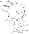
- Fig. 1 shows a schematic representation of a device 1 according to the invention for printing containers 10.
- the containers 10 are fed to the device via a feed device 52 and removed via a discharge device 54.
- the device 1 also has a carrier 24 which can be rotated with respect to an axis of rotation D and is part of a transport device 2.
- holding devices 22 are arranged, which are used to hold the containers 10 to be equipped (only one shown).
- printing units 4, 6, 7 are arranged on the carrier 24, but only three of these equipment units are shown.
- the reference numerals 14, 16 and 17 each relate to control devices for controlling the printing units 4, 6 and 7.
- the embodiment shown is a printing unit which applies a direct print to the containers 10.
- These printing units 4, 6, 7 can have a plurality of print heads, for example three print heads, which are arranged one above the other.
- the device has rotation devices which allow each individual container 10 to be rotated with respect to its longitudinal direction (which here runs perpendicular to the plane of the figure).
- the reference symbol P identifies the here circular transport path of the containers 10 to be equipped.
- An inspection device 8 which checks the containers, is arranged downstream with respect to the holding elements and the equipment units. This inspection device inspects these containers or their test markings in particular as part of a test operation of the device.
- the inspection device can have a storage device 32 in which reference images are stored, in particular reference images from test prints.
- the device also has a comparison device 34 which compares the recorded images of the test markings with the reference images. On the basis of this comparison, a pressure parameter of the control device can be changed, in particular in order to achieve an improvement in the pressure.
- Fig. 2 shows a flow chart for a method according to the invention.
- a test program or test procedure is initially started. This start can, as mentioned above, be triggered by the user, ie for example manually, but it would also be possible for the start to take place automatically according to certain specifications, for example after a product changeover.
- the reference numeral 18 denotes a storage device into which the inspection device can be brought, in particular during a production operation of the device 1.
- This storage device preferably has a housing which protects the inspection device at least against contamination such as paint splashes.
- the device can have a carrier (not shown), with respect to which the inspection device 8 can be displaced in order to move from a rest position (in Fig. 1 shown in dashed lines) to be moved into a working position (during a test operation).
- the reference number 12 identifies a further inspection device which inspects the containers (in particular during a production operation.
- the device preferably also has an assignment device (not shown) which assigns that printing unit which generated the inspected pressure to an inspection result of the further inspection device possible that this inspection device is arranged directly on a movable carrier, for example the discharge device 54.
- Fig. 2 two branches are now shown, the right branch illustrating actions of the inspection device and the left branch showing actions of the printing units.
- the at least one printing unit is switched to printing with the test marking.
- metadata it is possible for metadata to be printed in addition to the test marking, as mentioned above, for example a date or a time.
- an inspection device is activated at the beginning of the measurement program, which is also used to detect the test mark.
- this inspection device is moved, for example, out of an enclosure into a working or measuring position.
- a measuring sensor can be automatically brought into a suitable measuring position.
- a test object such as a container in particular, can then be retracted and printed with the test marking. This so printed container is then inspected by the inspection device and at least one measurement is carried out in the process. As part of this inspection, it is possible that one or more recordings of the test markings may be made.
- the recorded image or the measurements carried out are compared with reference images and, in particular, also reference colors.
- the test can be documented and, for this purpose, in particular the container provided with the test marking can also be discharged. If the inspection comes to the result that the test marking is unsatisfactory, a calibration takes place, in particular a calibration of the control device and / or the printing unit. In this case, another container is retracted and the test mark is printed. A measurement or an inspection of the test marking then takes place here again and it is checked whether this corresponds to the specified criteria. If necessary, these steps can be carried out several times. In particular, the method described here can run automatically and thus, in particular when production starts, perform a regulated calibration of the printing assemblies.
- the transport of the printed containers is preferably stopped in the area of the inspection device or the container transport is stopped. In this position, the container can then be scanned in a vertical direction. If, for example, a second scanning is necessary, the machine can be moved further by the necessary amount and, if necessary, the rotational position of the container relative to the measuring device can be corrected again and another image or another scanning can be carried out.
- the inspection device can, as mentioned above, be moved back to a protected area.
Landscapes
- Engineering & Computer Science (AREA)
- Manufacturing & Machinery (AREA)
- Investigating Materials By The Use Of Optical Means Adapted For Particular Applications (AREA)
- Spectrometry And Color Measurement (AREA)
- Inking, Control Or Cleaning Of Printing Machines (AREA)
- Accessory Devices And Overall Control Thereof (AREA)
Claims (7)
- Procédé d'impression de contenants en plastique (10), dans lequel les contenants (10) sont transportés le long d'un chemin de transport prédéterminé (P) et imprimés au moins temporairement sur leur surface extérieure au moyen d'au moins une unité d'impression (4, 6, 7), dans lequel un dispositif de commande (14, 16, 17) commande l'impression des contenants (10) par l'au moins une unité d'impression (4, 6, 7) sur la base d'au moins un paramètre d'impression,
caractérisé en ce que
pour déterminer ce paramètre d'impression, au moins un contenant en plastique (10) à imprimer est imprimé avec au moins un marquage de test puis ce contenant en plastique pourvu du marquage de test est inspecté au moyen d'au moins un dispositif de contrôle (8) qui est adapté et destiné à identifier au moins un défaut du marquage de test et les paramètres d'impression sont dérivés d'un résultat d'inspection de cette inspection, dans lequel le marquage de test est imprimé sur le contenant en plastique dans un mode de test et le marquage de test est un marquage de test spécial ou une image de test spéciale qui convient particulièrement pour évaluer et corriger ou déterminer les paramètres d'impression et qui est connu du dispositif d'inspection, dans lequel un marquage ou la pression à appliquer sur les contenants est vérifié lorsque l'appareil est en fonctionnement, dans lequel un dispositif d'inspection autre que le dispositif d'inspection utilisé pour le mode test est utilisé pour ce contrôle, dans lequel le dispositif d'inspection qui est utilisé dans le mode de fonction correspond à des critères différents du dispositif d'inspection qui est utilisé dans le mode de test. - Procédé selon au moins l'une des revendications précédentes,
caractérisé en ce que
un autre contenant en plastique est imprimé avec le marquage de test. - Procédé selon au moins l'une des revendications précédentes,
caractérisé en ce que
le marquage de test est comparé à au moins une valeur de référence. - Procédé selon au moins l'une des revendications précédentes,
caractérisé en ce que
le contenant en plastique (10) est imprimé avec au moins deux unités d'impression (4, 6, 7). - Procédé selon au moins l'une des revendications précédentes,
caractérisé en ce que
le dispositif d'inspection (8) évalue au moins une propriété de couleur du marquage. - Procédé selon au moins l'une des revendications précédentes,
caractérisé en ce que
le dispositif d'inspection (8) inspecte le marquage d'essai au moyen d'un élément d'inspection qui est choisi dans un groupe d'éléments d'inspection comprenant des spectrophotomètres, des densitomètres, en particulier des densitomètres de couleur et des densitomètres spectraux. - Dispositif d'impression de contenants en plastique (10), avec un dispositif de transport (2) qui transporte les contenants en plastique le long d'un chemin de transport prédéterminé, avec au moins une première unité d'impression (4, 6, 7) qui est adaptée et destinée à appliquer une pression sur une paroi extérieure du contentant en plastique (10) dans le cadre d'un mode de fonctionnement et avec un dispositif de commande (14, 16, 17) pour commander la première unité d'impression (4, 6, 7),
caractérisé en ce que
la première unité d'impression (4, 6, 7) est en outre adaptée et destinée à appliquer au moins un marquage de test sur une surface extérieure du contenant en plastique (10) au cours d'un mode de test, et avec un premier dispositif d'inspection (8) pour inspecter les contenants en plastique imprimés avec le marquage de test (10), lequel dispositif d'inspection (8) est disposé en aval de la première unité d'impression (4, 6, 7) dans le sens de transport des contenants en plastique (10) et qui produit au moins un résultat d'inspection qui peut être utilisé par le dispositif de commande (14, 16, 17) pour commander la première unité d'impression (4, 6, 7) et dans lequel le dispositif (1) a au moins un deuxième dispositif d'inspection (12) qui est adapté et destiné à inspecter les impressions appliquées aux contenants en plastique (10) pendant une un mode de fonctionnement, dans lequel un marquage ou la pression à appliquer sur les contenants est contrôlé pendant le fonctionnement du dispositif, dans lequel un dispositif d'inspection autre que le dispositif d'inspection utilisé pour le mode test est utilisé pour ce contrôle, dans lequel le dispositif d'inspection qui est utilisé dans le mode de fonctionnement correspond à des critères différents de celui du dispositif d'inspection qui est utilisé dans le mode de test.
Applications Claiming Priority (2)
| Application Number | Priority Date | Filing Date | Title |
|---|---|---|---|
| DE102014116201.3A DE102014116201A1 (de) | 2014-11-06 | 2014-11-06 | Vorrichtung und Verfahren zur Kontrolle von Direktdruckmaschinen |
| PCT/EP2015/075807 WO2016071444A1 (fr) | 2014-11-06 | 2015-11-05 | Dispositif et procédé de contrôle de machines d'impression directe |
Publications (2)
| Publication Number | Publication Date |
|---|---|
| EP3215367A1 EP3215367A1 (fr) | 2017-09-13 |
| EP3215367B1 true EP3215367B1 (fr) | 2021-03-10 |
Family
ID=54705559
Family Applications (1)
| Application Number | Title | Priority Date | Filing Date |
|---|---|---|---|
| EP15801343.3A Active EP3215367B1 (fr) | 2014-11-06 | 2015-11-05 | Dispositif et procédé de contrôle de machines d'impression directe |
Country Status (5)
| Country | Link |
|---|---|
| US (2) | US10144237B2 (fr) |
| EP (1) | EP3215367B1 (fr) |
| CN (1) | CN107148355B (fr) |
| DE (1) | DE102014116201A1 (fr) |
| WO (1) | WO2016071444A1 (fr) |
Families Citing this family (12)
| Publication number | Priority date | Publication date | Assignee | Title |
|---|---|---|---|---|
| DE102015114172A1 (de) * | 2015-08-26 | 2017-03-02 | Khs Gmbh | Verfahren und System zur Bedruckung von Behältern |
| DE102016212521A1 (de) | 2016-07-08 | 2018-01-11 | Krones Ag | Verfahren und Vorrichtung zum mehrfarbigen Tintenstrahldruck auf Behälter |
| DE102016114123A1 (de) | 2016-07-29 | 2018-02-01 | Khs Gmbh | Verfahren zur Bedruckung von Behältern |
| DE102017120259A1 (de) * | 2017-09-04 | 2019-03-07 | Krones Ag | Vorrichtung und Verfahren zum Kontrollieren von bedruckten Behältnissen |
| DE102017120281A1 (de) | 2017-09-04 | 2019-03-07 | Krones Ag | Vorrichtung und Verfahren zum Kontrollieren von bedruckten Behältnissen |
| DE102017215927A1 (de) * | 2017-09-08 | 2019-03-14 | Krones Aktiengesellschaft | Vorrichtung zum Ausschleusen von in einer Direktdruckmaschine fehlerhaft bedruckten Behältern |
| RU2750565C1 (ru) | 2017-09-19 | 2021-06-29 | Болл Корпорейшен | Машина для нанесения изображений на контейнеры и способ |
| DE102018102055A1 (de) * | 2018-01-30 | 2019-08-01 | Krones Ag | Vorrichtung und Verfahren zur Überprüfung der Etikettier- und/oder Druckgenauigkeit |
| DE102020102550A1 (de) | 2020-02-03 | 2021-08-05 | Krones Ag | Vorrichtung und Verfahren zum lagerichtigen Kennzeichnen von Behältern |
| IT202100011804A1 (it) * | 2021-05-07 | 2022-11-07 | Quantix Digital S R L | Macchina da stampa digitale a getto di inchiostro |
| CN114032746B (zh) * | 2021-11-16 | 2022-11-22 | 安徽省公路工程建设监理有限责任公司 | 一种道路桥梁打点设备 |
| DE102022131204A1 (de) | 2022-11-25 | 2024-05-29 | Krones Aktiengesellschaft | Verfahren zur Farbvermessung eines Drucksystems für den Tintenstrahl-Mehrfarbendruck auf Behälter |
Citations (7)
| Publication number | Priority date | Publication date | Assignee | Title |
|---|---|---|---|---|
| EP0761438A2 (fr) * | 1995-09-05 | 1997-03-12 | Tampoprint GmbH | Dispositif pour appliquer un motif |
| EP1011976A1 (fr) * | 1997-03-28 | 2000-06-28 | Jemtex Ink Jet Printing Ltd | Imprimante a jet d'encre et procede associe |
| WO2003106177A2 (fr) * | 2002-06-14 | 2003-12-24 | Aradex Ag | Dispositif de traitement de surface de pieces |
| JP2008089379A (ja) * | 2006-09-29 | 2008-04-17 | Hitachi Information & Control Solutions Ltd | 印字検査装置 |
| DE102009033810A1 (de) * | 2009-07-18 | 2011-01-27 | Till, Volker, Dipl.-Ing. | Anlage zum Bedrucken von Behältern |
| DE102011108754A1 (de) * | 2011-07-28 | 2013-01-31 | Khs Gmbh | Inspektionseinheit |
| WO2014076704A1 (fr) * | 2012-11-15 | 2014-05-22 | Velox-Puredigital Ltd. | Procédé et système d'impression |
Family Cites Families (21)
| Publication number | Priority date | Publication date | Assignee | Title |
|---|---|---|---|---|
| DE10065321A1 (de) * | 2000-12-30 | 2002-07-11 | Krones Ag | Inspektionsvorrichtung und -verfahren |
| US6982812B2 (en) * | 2001-01-22 | 2006-01-03 | Hewlett-Packard Development Company, L.P. | Calibration of printing devices |
| KR100958753B1 (ko) * | 2002-04-03 | 2010-05-19 | 메이소나이트 코오포레이션 | 물품에 상을 만드는 방법 및 장치 그리고 인쇄된 물품 |
| US20070019026A1 (en) * | 2005-07-25 | 2007-01-25 | Gibson Jason E | Printer |
| EP1832429A3 (fr) * | 2006-03-08 | 2008-05-28 | Homag Holzbearbeitungssysteme AG | Dispositif pour décorer des pièces à fabriquer |
| FR2908076B1 (fr) | 2006-11-03 | 2010-02-19 | Dubuit Mach | Poste d'impression,procede d'impression et machine a imprimer. |
| WO2009088867A2 (fr) * | 2007-12-31 | 2009-07-16 | Exatec, Llc | Procédé d'impression d'images haute qualité sur des substrats incurvés |
| ITRE20080065A1 (it) * | 2008-07-09 | 2010-01-10 | Sacmi | '' metodo e dispositivo per l erogazione controllata di sostanze colorate '' |
| JP5157856B2 (ja) * | 2008-12-03 | 2013-03-06 | セイコーエプソン株式会社 | 印刷制御装置、印刷システムおよび印刷制御プログラム |
| US8147026B2 (en) * | 2009-04-27 | 2012-04-03 | Eastman Kodak Company | Image quality matching in a mixed print engine assembly system |
| FI123465B (fi) * | 2009-05-11 | 2013-05-31 | Kemira Oyj | Koostumuksen käyttö mustesuihkupainatusominaisuuksien parantamiseksi |
| AT509149A3 (de) * | 2009-11-27 | 2012-03-15 | Durst Phototechnik Digital Technology Gmbh | Verfahren zur adaptiven anpassung des volumenstroms der ausgestossenen tinte |
| DE102010008295A1 (de) | 2010-02-17 | 2011-08-18 | Dieffenbacher System Automation GmbH, 75031 | Vorrichtung und Verfahren zum Bedrucken von Oberflächen von Werkstoffplatten, insbesondere Holzplatten, mit einer mehrfarbigen Abbildung |
| JP5713608B2 (ja) * | 2010-09-01 | 2015-05-07 | キヤノン株式会社 | プリント装置 |
| FR2974029B1 (fr) * | 2011-04-14 | 2014-01-17 | Serge Hasle Camille | Procede de tests d'impression sur un substrat et son dispositif de mise en oeuvre |
| DE102012005046A1 (de) | 2012-03-15 | 2013-09-19 | Till Gmbh | Verfahren zum Feststellen von Fehlern in der Ausrichtung von Druckbildern und zur Durchführung des Verfahrens eingerichtete Druckstation |
| US8955963B2 (en) * | 2012-04-27 | 2015-02-17 | Illinois Tool Works Inc. | System and method for printing on a flexible body |
| DE102012209305A1 (de) * | 2012-06-01 | 2013-12-05 | Krones Ag | Verfahren und Vorrichtung zur Kontrolle bzw. Korrektur eines Direktdrucks auf Behältern mit reliefartiger Oberflächenkontur |
| US9278552B2 (en) * | 2012-06-06 | 2016-03-08 | Canon Kabushiki Kaisha | Ink jet printing apparatus and control method thereof |
| US9079441B1 (en) * | 2014-03-31 | 2015-07-14 | Xerox Corporation | System for detecting inoperative inkjets in three-dimensional object printing using an optical sensor having an adjustable focus |
| DE102014112484A1 (de) | 2014-08-29 | 2016-03-03 | Krones Aktiengesellschaft | Vorrichtung und Verfahren zum Ausstatten von Behältnissen und Stationsstilllegung |
-
2014
- 2014-11-06 DE DE102014116201.3A patent/DE102014116201A1/de not_active Withdrawn
-
2015
- 2015-11-05 EP EP15801343.3A patent/EP3215367B1/fr active Active
- 2015-11-05 WO PCT/EP2015/075807 patent/WO2016071444A1/fr not_active Ceased
- 2015-11-05 CN CN201580059928.XA patent/CN107148355B/zh active Active
- 2015-11-05 US US15/523,016 patent/US10144237B2/en active Active
-
2018
- 2018-11-20 US US16/196,078 patent/US11014376B2/en active Active
Patent Citations (7)
| Publication number | Priority date | Publication date | Assignee | Title |
|---|---|---|---|---|
| EP0761438A2 (fr) * | 1995-09-05 | 1997-03-12 | Tampoprint GmbH | Dispositif pour appliquer un motif |
| EP1011976A1 (fr) * | 1997-03-28 | 2000-06-28 | Jemtex Ink Jet Printing Ltd | Imprimante a jet d'encre et procede associe |
| WO2003106177A2 (fr) * | 2002-06-14 | 2003-12-24 | Aradex Ag | Dispositif de traitement de surface de pieces |
| JP2008089379A (ja) * | 2006-09-29 | 2008-04-17 | Hitachi Information & Control Solutions Ltd | 印字検査装置 |
| DE102009033810A1 (de) * | 2009-07-18 | 2011-01-27 | Till, Volker, Dipl.-Ing. | Anlage zum Bedrucken von Behältern |
| DE102011108754A1 (de) * | 2011-07-28 | 2013-01-31 | Khs Gmbh | Inspektionseinheit |
| WO2014076704A1 (fr) * | 2012-11-15 | 2014-05-22 | Velox-Puredigital Ltd. | Procédé et système d'impression |
Also Published As
| Publication number | Publication date |
|---|---|
| US10144237B2 (en) | 2018-12-04 |
| US20190084327A1 (en) | 2019-03-21 |
| CN107148355A (zh) | 2017-09-08 |
| EP3215367A1 (fr) | 2017-09-13 |
| US11014376B2 (en) | 2021-05-25 |
| DE102014116201A1 (de) | 2016-05-12 |
| US20170313112A1 (en) | 2017-11-02 |
| WO2016071444A1 (fr) | 2016-05-12 |
| CN107148355B (zh) | 2019-07-09 |
Similar Documents
| Publication | Publication Date | Title |
|---|---|---|
| EP3215367B1 (fr) | Dispositif et procédé de contrôle de machines d'impression directe | |
| EP0884178B1 (fr) | Procédé pour reguler l'encrage dans une machine d'impression | |
| EP2011651B1 (fr) | Système d'inspection d'un image imprimé | |
| EP3456535B2 (fr) | Inspection d'image des produits imprimés avec des classes d'erreur | |
| DE3924989A1 (de) | Vorrichtung zur durchfuehrung einer umfassenden qualitaetskontrolle an druckbogen | |
| DE10319770A1 (de) | Verfahren zur Regelung der Farbdichte einer von einer Druckmaschine auf einem Druckträger aufgebrachten Farbe und Vorrichtung zur Regelung verschiedener für den Druckprozess einer Druckmaschine relevanter Parameter | |
| EP2033789A2 (fr) | Calibrage d'appareils de mesure de couleur dans une machine d'impression | |
| EP0356705B1 (fr) | Lecture de données pour un dispositif de réglage de l'encre | |
| EP3246161B1 (fr) | Dispositif d'inspection de produits imprimés | |
| DE102010009961A1 (de) | Inlinefarbregelung in Druckmaschinen | |
| DE102005026127A1 (de) | Druckmaschine und ein Verfahren zur Herstellung eines Druckerzeugnisses | |
| DE102014112484A1 (de) | Vorrichtung und Verfahren zum Ausstatten von Behältnissen und Stationsstilllegung | |
| DE102011014073A1 (de) | Verfahren zur Regelung eines Druckvorgangs | |
| DE102008031995B4 (de) | Automatische Bildfehlerkorrektur mittels neuer Druckplatten | |
| EP3186089B1 (fr) | Dispositif et procédé d'impression sur des contenants comprenant une détection d'erreurs | |
| DE102017213262B4 (de) | Bilderfassung mit bereichsweiser Bildauflösung | |
| EP0909647B1 (fr) | Console de commande pour une machine à imprimer | |
| DE102008033171A1 (de) | Verfahren und Vorrichtung zur Inline-Qualitätssicherung an Druckmaschinen | |
| EP4391517A1 (fr) | Procédure de détermination de la position des mesures spectrales | |
| DE102018125960A1 (de) | Verfahren und Vorrichtung zum Inspizieren von Behältnissen |
Legal Events
| Date | Code | Title | Description |
|---|---|---|---|
| STAA | Information on the status of an ep patent application or granted ep patent |
Free format text: STATUS: THE INTERNATIONAL PUBLICATION HAS BEEN MADE |
|
| PUAI | Public reference made under article 153(3) epc to a published international application that has entered the european phase |
Free format text: ORIGINAL CODE: 0009012 |
|
| STAA | Information on the status of an ep patent application or granted ep patent |
Free format text: STATUS: REQUEST FOR EXAMINATION WAS MADE |
|
| 17P | Request for examination filed |
Effective date: 20170606 |
|
| AK | Designated contracting states |
Kind code of ref document: A1 Designated state(s): AL AT BE BG CH CY CZ DE DK EE ES FI FR GB GR HR HU IE IS IT LI LT LU LV MC MK MT NL NO PL PT RO RS SE SI SK SM TR |
|
| AX | Request for extension of the european patent |
Extension state: BA ME |
|
| DAV | Request for validation of the european patent (deleted) | ||
| DAX | Request for extension of the european patent (deleted) | ||
| STAA | Information on the status of an ep patent application or granted ep patent |
Free format text: STATUS: EXAMINATION IS IN PROGRESS |
|
| 17Q | First examination report despatched |
Effective date: 20200330 |
|
| GRAP | Despatch of communication of intention to grant a patent |
Free format text: ORIGINAL CODE: EPIDOSNIGR1 |
|
| STAA | Information on the status of an ep patent application or granted ep patent |
Free format text: STATUS: GRANT OF PATENT IS INTENDED |
|
| INTG | Intention to grant announced |
Effective date: 20200923 |
|
| GRAS | Grant fee paid |
Free format text: ORIGINAL CODE: EPIDOSNIGR3 |
|
| GRAA | (expected) grant |
Free format text: ORIGINAL CODE: 0009210 |
|
| STAA | Information on the status of an ep patent application or granted ep patent |
Free format text: STATUS: THE PATENT HAS BEEN GRANTED |
|
| AK | Designated contracting states |
Kind code of ref document: B1 Designated state(s): AL AT BE BG CH CY CZ DE DK EE ES FI FR GB GR HR HU IE IS IT LI LT LU LV MC MK MT NL NO PL PT RO RS SE SI SK SM TR |
|
| REG | Reference to a national code |
Ref country code: GB Ref legal event code: FG4D Free format text: NOT ENGLISH |
|
| REG | Reference to a national code |
Ref country code: AT Ref legal event code: REF Ref document number: 1369378 Country of ref document: AT Kind code of ref document: T Effective date: 20210315 Ref country code: CH Ref legal event code: EP |
|
| REG | Reference to a national code |
Ref country code: IE Ref legal event code: FG4D Free format text: LANGUAGE OF EP DOCUMENT: GERMAN |
|
| REG | Reference to a national code |
Ref country code: DE Ref legal event code: R096 Ref document number: 502015014391 Country of ref document: DE |
|
| REG | Reference to a national code |
Ref country code: LT Ref legal event code: MG9D |
|
| PG25 | Lapsed in a contracting state [announced via postgrant information from national office to epo] |
Ref country code: NO Free format text: LAPSE BECAUSE OF FAILURE TO SUBMIT A TRANSLATION OF THE DESCRIPTION OR TO PAY THE FEE WITHIN THE PRESCRIBED TIME-LIMIT Effective date: 20210610 Ref country code: LT Free format text: LAPSE BECAUSE OF FAILURE TO SUBMIT A TRANSLATION OF THE DESCRIPTION OR TO PAY THE FEE WITHIN THE PRESCRIBED TIME-LIMIT Effective date: 20210310 Ref country code: GR Free format text: LAPSE BECAUSE OF FAILURE TO SUBMIT A TRANSLATION OF THE DESCRIPTION OR TO PAY THE FEE WITHIN THE PRESCRIBED TIME-LIMIT Effective date: 20210611 Ref country code: FI Free format text: LAPSE BECAUSE OF FAILURE TO SUBMIT A TRANSLATION OF THE DESCRIPTION OR TO PAY THE FEE WITHIN THE PRESCRIBED TIME-LIMIT Effective date: 20210310 Ref country code: HR Free format text: LAPSE BECAUSE OF FAILURE TO SUBMIT A TRANSLATION OF THE DESCRIPTION OR TO PAY THE FEE WITHIN THE PRESCRIBED TIME-LIMIT Effective date: 20210310 Ref country code: BG Free format text: LAPSE BECAUSE OF FAILURE TO SUBMIT A TRANSLATION OF THE DESCRIPTION OR TO PAY THE FEE WITHIN THE PRESCRIBED TIME-LIMIT Effective date: 20210610 |
|
| REG | Reference to a national code |
Ref country code: NL Ref legal event code: MP Effective date: 20210310 |
|
| PG25 | Lapsed in a contracting state [announced via postgrant information from national office to epo] |
Ref country code: LV Free format text: LAPSE BECAUSE OF FAILURE TO SUBMIT A TRANSLATION OF THE DESCRIPTION OR TO PAY THE FEE WITHIN THE PRESCRIBED TIME-LIMIT Effective date: 20210310 Ref country code: RS Free format text: LAPSE BECAUSE OF FAILURE TO SUBMIT A TRANSLATION OF THE DESCRIPTION OR TO PAY THE FEE WITHIN THE PRESCRIBED TIME-LIMIT Effective date: 20210310 Ref country code: SE Free format text: LAPSE BECAUSE OF FAILURE TO SUBMIT A TRANSLATION OF THE DESCRIPTION OR TO PAY THE FEE WITHIN THE PRESCRIBED TIME-LIMIT Effective date: 20210310 |
|
| PG25 | Lapsed in a contracting state [announced via postgrant information from national office to epo] |
Ref country code: NL Free format text: LAPSE BECAUSE OF FAILURE TO SUBMIT A TRANSLATION OF THE DESCRIPTION OR TO PAY THE FEE WITHIN THE PRESCRIBED TIME-LIMIT Effective date: 20210310 |
|
| PG25 | Lapsed in a contracting state [announced via postgrant information from national office to epo] |
Ref country code: SM Free format text: LAPSE BECAUSE OF FAILURE TO SUBMIT A TRANSLATION OF THE DESCRIPTION OR TO PAY THE FEE WITHIN THE PRESCRIBED TIME-LIMIT Effective date: 20210310 Ref country code: CZ Free format text: LAPSE BECAUSE OF FAILURE TO SUBMIT A TRANSLATION OF THE DESCRIPTION OR TO PAY THE FEE WITHIN THE PRESCRIBED TIME-LIMIT Effective date: 20210310 Ref country code: EE Free format text: LAPSE BECAUSE OF FAILURE TO SUBMIT A TRANSLATION OF THE DESCRIPTION OR TO PAY THE FEE WITHIN THE PRESCRIBED TIME-LIMIT Effective date: 20210310 |
|
| PG25 | Lapsed in a contracting state [announced via postgrant information from national office to epo] |
Ref country code: IS Free format text: LAPSE BECAUSE OF FAILURE TO SUBMIT A TRANSLATION OF THE DESCRIPTION OR TO PAY THE FEE WITHIN THE PRESCRIBED TIME-LIMIT Effective date: 20210710 Ref country code: PL Free format text: LAPSE BECAUSE OF FAILURE TO SUBMIT A TRANSLATION OF THE DESCRIPTION OR TO PAY THE FEE WITHIN THE PRESCRIBED TIME-LIMIT Effective date: 20210310 Ref country code: PT Free format text: LAPSE BECAUSE OF FAILURE TO SUBMIT A TRANSLATION OF THE DESCRIPTION OR TO PAY THE FEE WITHIN THE PRESCRIBED TIME-LIMIT Effective date: 20210712 Ref country code: SK Free format text: LAPSE BECAUSE OF FAILURE TO SUBMIT A TRANSLATION OF THE DESCRIPTION OR TO PAY THE FEE WITHIN THE PRESCRIBED TIME-LIMIT Effective date: 20210310 Ref country code: RO Free format text: LAPSE BECAUSE OF FAILURE TO SUBMIT A TRANSLATION OF THE DESCRIPTION OR TO PAY THE FEE WITHIN THE PRESCRIBED TIME-LIMIT Effective date: 20210310 |
|
| REG | Reference to a national code |
Ref country code: DE Ref legal event code: R097 Ref document number: 502015014391 Country of ref document: DE |
|
| PLBE | No opposition filed within time limit |
Free format text: ORIGINAL CODE: 0009261 |
|
| STAA | Information on the status of an ep patent application or granted ep patent |
Free format text: STATUS: NO OPPOSITION FILED WITHIN TIME LIMIT |
|
| PG25 | Lapsed in a contracting state [announced via postgrant information from national office to epo] |
Ref country code: AL Free format text: LAPSE BECAUSE OF FAILURE TO SUBMIT A TRANSLATION OF THE DESCRIPTION OR TO PAY THE FEE WITHIN THE PRESCRIBED TIME-LIMIT Effective date: 20210310 Ref country code: ES Free format text: LAPSE BECAUSE OF FAILURE TO SUBMIT A TRANSLATION OF THE DESCRIPTION OR TO PAY THE FEE WITHIN THE PRESCRIBED TIME-LIMIT Effective date: 20210310 Ref country code: DK Free format text: LAPSE BECAUSE OF FAILURE TO SUBMIT A TRANSLATION OF THE DESCRIPTION OR TO PAY THE FEE WITHIN THE PRESCRIBED TIME-LIMIT Effective date: 20210310 |
|
| 26N | No opposition filed |
Effective date: 20211213 |
|
| PG25 | Lapsed in a contracting state [announced via postgrant information from national office to epo] |
Ref country code: SI Free format text: LAPSE BECAUSE OF FAILURE TO SUBMIT A TRANSLATION OF THE DESCRIPTION OR TO PAY THE FEE WITHIN THE PRESCRIBED TIME-LIMIT Effective date: 20210310 |
|
| PG25 | Lapsed in a contracting state [announced via postgrant information from national office to epo] |
Ref country code: IS Free format text: LAPSE BECAUSE OF FAILURE TO SUBMIT A TRANSLATION OF THE DESCRIPTION OR TO PAY THE FEE WITHIN THE PRESCRIBED TIME-LIMIT Effective date: 20210710 |
|
| PG25 | Lapsed in a contracting state [announced via postgrant information from national office to epo] |
Ref country code: MC Free format text: LAPSE BECAUSE OF FAILURE TO SUBMIT A TRANSLATION OF THE DESCRIPTION OR TO PAY THE FEE WITHIN THE PRESCRIBED TIME-LIMIT Effective date: 20210310 |
|
| REG | Reference to a national code |
Ref country code: CH Ref legal event code: PL |
|
| GBPC | Gb: european patent ceased through non-payment of renewal fee |
Effective date: 20211105 |
|
| PG25 | Lapsed in a contracting state [announced via postgrant information from national office to epo] |
Ref country code: LU Free format text: LAPSE BECAUSE OF NON-PAYMENT OF DUE FEES Effective date: 20211105 Ref country code: BE Free format text: LAPSE BECAUSE OF NON-PAYMENT OF DUE FEES Effective date: 20211130 |
|
| REG | Reference to a national code |
Ref country code: BE Ref legal event code: MM Effective date: 20211130 |
|
| PG25 | Lapsed in a contracting state [announced via postgrant information from national office to epo] |
Ref country code: LI Free format text: LAPSE BECAUSE OF NON-PAYMENT OF DUE FEES Effective date: 20211130 Ref country code: CH Free format text: LAPSE BECAUSE OF NON-PAYMENT OF DUE FEES Effective date: 20211130 |
|
| PG25 | Lapsed in a contracting state [announced via postgrant information from national office to epo] |
Ref country code: IE Free format text: LAPSE BECAUSE OF NON-PAYMENT OF DUE FEES Effective date: 20211105 Ref country code: GB Free format text: LAPSE BECAUSE OF NON-PAYMENT OF DUE FEES Effective date: 20211105 |
|
| REG | Reference to a national code |
Ref country code: AT Ref legal event code: MM01 Ref document number: 1369378 Country of ref document: AT Kind code of ref document: T Effective date: 20211105 |
|
| PG25 | Lapsed in a contracting state [announced via postgrant information from national office to epo] |
Ref country code: AT Free format text: LAPSE BECAUSE OF NON-PAYMENT OF DUE FEES Effective date: 20211105 |
|
| PG25 | Lapsed in a contracting state [announced via postgrant information from national office to epo] |
Ref country code: HU Free format text: LAPSE BECAUSE OF FAILURE TO SUBMIT A TRANSLATION OF THE DESCRIPTION OR TO PAY THE FEE WITHIN THE PRESCRIBED TIME-LIMIT; INVALID AB INITIO Effective date: 20151105 |
|
| PG25 | Lapsed in a contracting state [announced via postgrant information from national office to epo] |
Ref country code: CY Free format text: LAPSE BECAUSE OF FAILURE TO SUBMIT A TRANSLATION OF THE DESCRIPTION OR TO PAY THE FEE WITHIN THE PRESCRIBED TIME-LIMIT Effective date: 20210310 |
|
| PG25 | Lapsed in a contracting state [announced via postgrant information from national office to epo] |
Ref country code: MK Free format text: LAPSE BECAUSE OF FAILURE TO SUBMIT A TRANSLATION OF THE DESCRIPTION OR TO PAY THE FEE WITHIN THE PRESCRIBED TIME-LIMIT Effective date: 20210310 |
|
| PG25 | Lapsed in a contracting state [announced via postgrant information from national office to epo] |
Ref country code: TR Free format text: LAPSE BECAUSE OF FAILURE TO SUBMIT A TRANSLATION OF THE DESCRIPTION OR TO PAY THE FEE WITHIN THE PRESCRIBED TIME-LIMIT Effective date: 20210310 |
|
| PG25 | Lapsed in a contracting state [announced via postgrant information from national office to epo] |
Ref country code: MT Free format text: LAPSE BECAUSE OF FAILURE TO SUBMIT A TRANSLATION OF THE DESCRIPTION OR TO PAY THE FEE WITHIN THE PRESCRIBED TIME-LIMIT Effective date: 20210310 |
|
| PGFP | Annual fee paid to national office [announced via postgrant information from national office to epo] |
Ref country code: FR Payment date: 20250930 Year of fee payment: 11 |
|
| PGFP | Annual fee paid to national office [announced via postgrant information from national office to epo] |
Ref country code: DE Payment date: 20250930 Year of fee payment: 11 |
|
| PGFP | Annual fee paid to national office [announced via postgrant information from national office to epo] |
Ref country code: IT Payment date: 20251022 Year of fee payment: 11 |