EP0909669A1 - Luftbehandlungsgehäuse mit verbesserter Temperaturverwaltung, für eine Heizungs- und/oder Klimaanlage, insbesondere für Kraftfahrzeuge - Google Patents
Luftbehandlungsgehäuse mit verbesserter Temperaturverwaltung, für eine Heizungs- und/oder Klimaanlage, insbesondere für Kraftfahrzeuge Download PDFInfo
- Publication number
- EP0909669A1 EP0909669A1 EP98119264A EP98119264A EP0909669A1 EP 0909669 A1 EP0909669 A1 EP 0909669A1 EP 98119264 A EP98119264 A EP 98119264A EP 98119264 A EP98119264 A EP 98119264A EP 0909669 A1 EP0909669 A1 EP 0909669A1
- Authority
- EP
- European Patent Office
- Prior art keywords
- air
- mixing chamber
- line segment
- line
- fresh
- Prior art date
- Legal status (The legal status is an assumption and is not a legal conclusion. Google has not performed a legal analysis and makes no representation as to the accuracy of the status listed.)
- Withdrawn
Links
Images

Classifications
-
- B—PERFORMING OPERATIONS; TRANSPORTING
- B60—VEHICLES IN GENERAL
- B60H—ARRANGEMENTS OF HEATING, COOLING, VENTILATING OR OTHER AIR-TREATING DEVICES SPECIALLY ADAPTED FOR PASSENGER OR GOODS SPACES OF VEHICLES
- B60H1/00—Heating, cooling or ventilating devices
- B60H1/00007—Combined heating, ventilating, or cooling devices
- B60H1/00021—Air flow details of HVAC devices
- B60H1/00064—Air flow details of HVAC devices for sending air streams of different temperatures into the passenger compartment
- B60H1/00071—Air flow details of HVAC devices for sending air streams of different temperatures into the passenger compartment the air passing only one heat exchanger
Definitions
- the invention relates to the field of heating installations. and / or air conditioning, in particular for a motor vehicle, and more particularly the treatment and distribution box some of these installations.
- It relates more particularly to the housings in which can be obtained a temperature management of different air flows which respectively supply the distribution ducts opening into the passenger compartment of the vehicle by defrost, middle ventilation and foot ventilation, in particular.
- Such boxes generally include an air inlet which feeds, in a controlled manner through a mixing flap, a mixing chamber, supplying treated air to the distribution, and a heating chamber which opens into this mixing chamber.
- treated air is meant here both fresh air intended to directly supply at least one of the distribution, without preheating, only air heated or refrigerated intended to supply these same ducts.
- An object of the invention is therefore to provide a housing of air treatment for a heating and / or installation air conditioning to remedy the drawback cited above.
- the invention proposes for this purpose a case of the type described previously which is shaped so that the air flows fresh and heated air entering the room mixing have contained cross sections in first and second planes which intersect respectively along a line of intersection and whose projections on the intersection line are formed respectively at least a first line segment and at least one second segment of straight line not confused and presenting at least a common part.
- the air flows open into the room mixing at partially identical levels, so that in the region or regions where their levels are identical they can be mixed, while in regions where their levels are not identical they remain substantially independent of each other. This ensures a efficient management of indoor air stratification of the mixing chamber.
- the mixing chamber has an extension in the direction parallel to the intersection line at least equal to the meeting of said first (s) and second (s) line segment.
- the word “meeting” is here understood in its mathematical definition, namely “set of common and uncommon portions of the first and second line segments ". This allows air flows to different temperatures to remain not substantially mixed inside the mixing chamber, until that they reach the distribution conduits.
- the projection of the cross section of each air flow entering the mixing chamber is consisting of a single line segment, first or second depending on whether it is fresh (or refrigerated) air or air warmed up. But, it is clear that a section projection transverse air flow can be made up of several line segments.
- the second line segment of the projection of the transverse surface of the heated air flow on the intersection right extends beyond one at least of the two ends of the first line segment of the projection of the transverse surface of the fresh air flow on the intersection right.
- the heating preferably present, at least at where it communicates with the mixing chamber, a cross section including extension in direction parallel to the intersection line is greater than that of the cross section of the incoming fresh air flow in this mixing chamber.
- the second segment (air heated) is therefore completely superimposed on the first segment (fresh air), and exceeds it, so that you create a mixed air layer (fresh air and heated air) and at least a layer of heated air.
- the heating chamber may, in particular, present in the direction parallel to the intersection line, at the mixing chamber, an extension such as the second line segment extends beyond the two ends of the first line segment, thus supplying air heated to the same temperature two ducts distribution placed substantially symmetrically on the side and else in the region where the fresh air and air flows reheated are mixed.
- the mixed air layer is in this case between two layers of heated air.
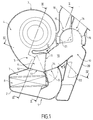
- Figure 1 In Figure 1 is shown, in a sectional view longitudinal center, a box 1 for treatment and air distribution partially materialized by two generators parallels 2 delimiting the thickness of its walls.
- a such housing is part of a heating-ventilation installation, for example of a motor vehicle.
- this type of housing is to provide treated air to the interior of the vehicle interior via outlet, such as the defrost vents at the base of the windshield, the so-called “middle” air vents placed in the dashboard of the vehicle, and the vents aeration known as "feet" placed at the feet of the passengers housed in the passenger compartment.
- outlet such as the defrost vents at the base of the windshield, the so-called “middle” air vents placed in the dashboard of the vehicle, and the vents aeration known as "feet" placed at the feet of the passengers housed in the passenger compartment.
- treated air is meant here fresh unheated air, or warm heated air. In the case of an installation air conditioning, it could also be air cooled.
- the fresh air which is treated by the box 1 comes from a motor-fan unit 3 whose blower is supplied by air from outside (air called outside) or by air from inside the passenger compartment (so-called recirculated air).
- the pulser includes a volute 4, the output 5 of which supplies an air inlet 6 of the housing 1.
- the scroll 4 is formed in one piece with the housing 1.
- the housing 1 may include fixing means allowing its coupling to the blower, and in particular its connection to the volute 4.
- the housing 1 comprises downstream of the air inlet 6 a chamber heater 7 in which is located a radiator heater 8 intended to heat all or part of the air external or recirculated fresh from the blower via the inlet air 6.
- the heating chamber 7 opens at an entrance said heated air inlet 9 of a mixing chamber 10.
- This mixing chamber 10 includes another air inlet 11 said fresh air inlet which, in the example illustrated on the Figure 1 is located near the air inlet 6, and downstream of it.
- Access to the fresh air inlet 11 and the mixing chamber 7 is controlled, in this example, by a first part 12 a mixing panel 13.
- the mixing flap 13 comprises a second part 14 which extends the first part 12 and which controls access to the hot air inlet 9 of the mixing 10 (or exit from the heating chamber 7).
- case could also include a fresh air supply chamber (or duct) between the air inlet 6 and the fresh air inlet 11.
- the mixing flap 13 can take a multiplicity of positions to allow temperature management air at the level of the mixing chamber 10. These different positions of the mixing flap 13 are between a position in which the fresh air inlet 11 is completely obstructed, and therefore all the fresh air from the blower is heated in heating chamber 7 and opens into the mixing chamber 10 through the air inlet warmed up 9, and a position in which access to the heating chamber 7 is totally prohibited, and by therefore all the fresh air from the blower opens into the mixing chamber 10 via the fresh air inlet 11. In this last position, the second part 14 of the mixing flap 13 completely shut off the heated air inlet 9.
- the mixing chamber 10 has three outputs, called defrost outlet 15 respectively, middle ventilation outlet 16 and outlet ventilation feet 17, respectively intended for supply air ducts opening into the passenger compartment of the vehicle at defrost, ventilation openings median, and aeration feet.
- the outputs 15, 16 and 17 actually feed pre-conduits 18, 19 and 20 formed in box 1 and intended to be connected to the different installation air supply ducts.
- the housing 1 is shaped, at the level of the downstream part of the mixing chamber 10 which supplies its different outlets, so that a first distribution flap 21 manages both access to exits 15 and 16, while that a second distribution flap 22 manages access to the ventilation outlet feet 17, and more precisely at the preconduit 20.
- the first distribution flap 21 can take at least 2 intermediate positions included between an "aeration” position in which the outlet of defrost 15 is completely obstructed while the outlet middle vent 16 is fully released and one position "defrost” in which the middle ventilation outlet 16 is fully closed while defrost outlet 15 is totally liberated.
- the air which feeds the mouths defrost should preferably be significantly more hot as the air that feeds the air vents feet.
- the housing according to the invention is capable of offering a stratification of the temperature, ensuring such a bilevel mode.
- the housing 1 according to the invention is shaped so that the fresh air and heated air flows which enter the mixing chamber 10 respectively by the fresh air inlet 11 and the heated air inlet 9 open into the interior of the mixing chamber 10 at levels that are not completely stackable. This arrangement is best illustrated in Figures 2 to 4.
- the fresh and heated air flows that enter the interior of the mixing chamber 10 have, at its two entrances 11 and 9, contained cross sections respectively in first P1 and second P2 planes which intersect along a line of intersection D (see figure 5) and whose projections on this straight line D are respectively of the first S1 and second S2 line segments having at least one common part.
- cross section here is meant a perpendicular section to the average direction of the air flow concerned.
- the cross section of the fresh air flow at the level of the fresh air inlet 11 is substantially equal on the surface of this fresh air inlet 11, while the cross section of the heated air flow at the heated air inlet 9 is substantially equal to the surface of this air inlet 9.
- the mixing flap 13 When the mixing flap 13 is in a position intermediate in which the fresh air from the blower 3 is distributed at the fresh air inlet 11 and the heating chamber 7 so as to open out at the heated air inlet 9, it forms in the upstream part of the mixing chamber 10, located near its inputs 11 and 9, three layers, an upper layer L1, a layer central L2, and a lower layer L3.
- Qualifiers "upper” and “lower” are understood here in relation to a straight D vertical.
- the upper layer L1 is a layer heated air (shown in Figures 2 to 4 by points), coming from the upper part of the heater 7, which at the heated air inlet 9 extends above and below the level of the air inlet fresh 11.
- the intermediate layer L2 consists of an air said mixed resulting from the mixture between the heated air from the heating chamber 7 and fresh air reaching the level of the fresh air inlet 11. In FIGS. 2 to 4, this mixed air is materialized by crosses. Inside the mixing chamber 10, the mixed air layer extends over a height substantially equal to the extension of segment S1, at less in the upstream part of the mixing chamber 10. Finally, the lower layer L3 is formed of heated air coming from the lower part of the heating chamber 7.
- the mixed air layer is therefore framed in these upper and lower parts by layers of heated air.
- the thicknesses respective layers of heated air L1 and L3 in the mixing chamber are substantially equal.
- the extensions of the S2 segment on either side of ends of segment S1 are substantially equal.
- the three-layer structure symmetrical to supply two conduits defrosting 18a and 18b, and / or middle ventilation 19a and 19b, placed respectively at the level of the lower layers L3 and upper L1 at the outlet of mixing chamber 10 (part downstream).
- this chamber mixer and therefore the housing 1 has a extension (or height) in direction D substantially equal to the extension of the S2 segment, or in other words to the height of the heated air inlet 9.
- this extension of the mixing chamber 10 is slightly larger than that of the S2 segment.
- extension of the feet ventilation outlet 17 is advantageously equal to that of the segment S2.
- the air entering the air vent 20 feet is consisting of the superposition of the three layers L1, L2 and L3 and therefore the temperature of the air that reaches the level of the air vents feet is intermediate between the temperature of the heated air in layers L1 and L3 and the mixed air of the intermediate layer L2.
- the air that feeds the vents defrost consists mainly of air heated in from the upper L1 and lower L3 layers.
- the heating chamber 7 present downstream of the radiator 8 an extension in direction D substantially equal to S2, while the extension in this same direction D of the part of the housing included upstream of the radiator 8, as well as between the air inlet 6 and the fresh air inlet 11, is substantially equal to S1.
- a housing according to the invention it is therefore possible to supply a large number of distribution outlets of air placed in the passenger compartment with air flows of different temperatures, some being supplied with air fresh, some others in heated air, some others still looking mixed. We could even consider more three different temperatures.
- the fresh air entering the room mixing by the fresh air intake will consist of air cooled.
Landscapes
- Physics & Mathematics (AREA)
- Thermal Sciences (AREA)
- Engineering & Computer Science (AREA)
- Mechanical Engineering (AREA)
- Air-Conditioning For Vehicles (AREA)
Applications Claiming Priority (2)
| Application Number | Priority Date | Filing Date | Title |
|---|---|---|---|
| FR9712843A FR2769692B1 (fr) | 1997-10-14 | 1997-10-14 | Boitier de traitement d'air a gestion de temperature perfectionnee, pour une installation de chauffage et/ou climatisation, notamment de vehicule automobile |
| FR9712843 | 1997-10-14 |
Publications (1)
| Publication Number | Publication Date |
|---|---|
| EP0909669A1 true EP0909669A1 (de) | 1999-04-21 |
Family
ID=9512214
Family Applications (1)
| Application Number | Title | Priority Date | Filing Date |
|---|---|---|---|
| EP98119264A Withdrawn EP0909669A1 (de) | 1997-10-14 | 1998-10-13 | Luftbehandlungsgehäuse mit verbesserter Temperaturverwaltung, für eine Heizungs- und/oder Klimaanlage, insbesondere für Kraftfahrzeuge |
Country Status (2)
| Country | Link |
|---|---|
| EP (1) | EP0909669A1 (de) |
| FR (1) | FR2769692B1 (de) |
Cited By (2)
| Publication number | Priority date | Publication date | Assignee | Title |
|---|---|---|---|---|
| DE19943646C1 (de) * | 1999-09-13 | 2000-12-14 | Daimler Chrysler Ag | Vorrichtung zur Beheizung und Klimatisierung eines Fahrzeuginnenraums |
| EP1514708A1 (de) * | 2003-09-12 | 2005-03-16 | Valeo Climatisation | Heiz und/oder Klimatiserungsvorrichtung für Fahrzeuginnenraum, mit hoch entwickelter aerothermischer Regelung |
Citations (3)
| Publication number | Priority date | Publication date | Assignee | Title |
|---|---|---|---|---|
| FR2562845A1 (fr) * | 1984-04-13 | 1985-10-18 | Chausson Usines Sa | Dispositif climatiseur pour vehicules |
| FR2710878A1 (fr) * | 1993-10-07 | 1995-04-14 | Valeo Thermique Habitacle | Dispositif du chauffage et de ventilation de l'habitacle d'un véhicule automobile. |
| FR2737156A1 (fr) * | 1995-07-24 | 1997-01-31 | Valeo Climatisation | Dispositif de chauffage-ventilation de l'habitacle d'un vehicule automobile |
-
1997
- 1997-10-14 FR FR9712843A patent/FR2769692B1/fr not_active Expired - Fee Related
-
1998
- 1998-10-13 EP EP98119264A patent/EP0909669A1/de not_active Withdrawn
Patent Citations (3)
| Publication number | Priority date | Publication date | Assignee | Title |
|---|---|---|---|---|
| FR2562845A1 (fr) * | 1984-04-13 | 1985-10-18 | Chausson Usines Sa | Dispositif climatiseur pour vehicules |
| FR2710878A1 (fr) * | 1993-10-07 | 1995-04-14 | Valeo Thermique Habitacle | Dispositif du chauffage et de ventilation de l'habitacle d'un véhicule automobile. |
| FR2737156A1 (fr) * | 1995-07-24 | 1997-01-31 | Valeo Climatisation | Dispositif de chauffage-ventilation de l'habitacle d'un vehicule automobile |
Cited By (3)
| Publication number | Priority date | Publication date | Assignee | Title |
|---|---|---|---|---|
| DE19943646C1 (de) * | 1999-09-13 | 2000-12-14 | Daimler Chrysler Ag | Vorrichtung zur Beheizung und Klimatisierung eines Fahrzeuginnenraums |
| EP1514708A1 (de) * | 2003-09-12 | 2005-03-16 | Valeo Climatisation | Heiz und/oder Klimatiserungsvorrichtung für Fahrzeuginnenraum, mit hoch entwickelter aerothermischer Regelung |
| FR2859665A1 (fr) * | 2003-09-12 | 2005-03-18 | Valeo Climatisation | Dispositif de chauffage et/ou climatisation d'habitacle, a gestion aerothermique perfectionnee |
Also Published As
| Publication number | Publication date |
|---|---|
| FR2769692B1 (fr) | 2000-01-07 |
| FR2769692A1 (fr) | 1999-04-16 |
Similar Documents
| Publication | Publication Date | Title |
|---|---|---|
| EP0936090B1 (de) | Heiz- und/oder Klimatisierungsvorrichtung eines Kraftfahrzeuges mit verbessertem Wärmetausch-Management | |
| EP1062109B1 (de) | Lüftung, heizung und/oder klimaanlage des fahrgastraumes eines kraftfahrzeuges | |
| FR2659907A1 (fr) | Dispositif de chauffage et de ventilation avec moyens separes de reglage de temperature aux places avant de l'habitacle d'un vehicule automobile. | |
| WO2001062530A1 (fr) | Dispositif de conditionnement d'air pour vehicule | |
| FR2703304A1 (fr) | Boîtier de distribution pour une installation de chauffage-ventilation de l'habitacle d'un véhicule automobile. | |
| EP3319824A1 (de) | Kraftfahrzeugheiz-, belüftungs- und/oder klimatisierungsvorrichtung und entsprechendes zusatzmodul und montageverfahren | |
| EP0780251B1 (de) | Vorrichtung für die Heizung, Lüftung und/oder Klimatisierung, insbesondere für Kraftwagen | |
| FR2717747A1 (fr) | Installation de chauffage-climatisation pour l'habitacle d'un véhicule automobile. | |
| FR2742383A1 (fr) | Dispositif de chauffage et/ou climatisation de l'habitacle d'un vehicule automobile | |
| FR2789629A1 (fr) | Installation de chauffage et/ou climatisation a mixage d'air pour vehicule automobile | |
| FR2787392A1 (fr) | Dispositif de chauffage-climatisaiton d'encombrement reduit pour vehicule automobile | |
| EP0289405A1 (de) | Heizungs- und Belüftungsgerät, insbesondere für den Fahrgastraum eines Kraftfahrzeugs | |
| EP1090785B1 (de) | Verbessertes Luftbehandlungsgehäuse eines Innenraums insbesondere eines Kraftfahrzeugs | |
| FR2765526A1 (fr) | Installation de chauffage et/ou climatisation, notamment de vehicule automobile, equipee d'un boitier de traitement d'air a distribution d'air perfectionne | |
| EP0961698B1 (de) | Heizungs- und/oder klimaanlage, integriert in einem fahrzeugarmaturenbrett | |
| FR2795684A1 (fr) | Dispositif perfectionne de chauffage, ventilation et/ou climatisation d'un habitacle, notamment de vehicule automobile, a reglage de temperature par zones | |
| FR2769692A1 (fr) | Boitier de traitement d'air a gestion de temperature perfectionnee, pour une installation de chauffage et/ou climatisation, notamment de vehicule automobile | |
| EP1514708B1 (de) | Heiz und/oder Klimatiserungsvorrichtung für Fahrzeuginnenraum, mit hoch entwickelter aerothermischer Regelung | |
| EP2106941B1 (de) | Kraftfahrzeugklimaanlage | |
| FR2795683A1 (fr) | Dispositif de chauffage et/ou climatisation d'un habitacle, notamment de vehicule automobile, a conduit transversal | |
| FR2762552A1 (fr) | Dispositif de ventilation pour l'habitacle de vehicules automobiles | |
| EP0751021B1 (de) | Heizungs- und/oder Klimaanlage für ein Kraftfahrzeug | |
| FR2783465A1 (fr) | Dispositif de chauffage-climatisation integre dans une planche de bord de vehicule automobile | |
| EP1510379B1 (de) | Luftverteilungsmodul für eine Heiz-Lüftungs- oder Klimaanlage eines Fahrgastraumes | |
| FR2781428A1 (fr) | Dispositif de chauffage-ventilation pour vehicule automobile, a commande individuelle selon les zones de l'habitacle |
Legal Events
| Date | Code | Title | Description |
|---|---|---|---|
| PUAI | Public reference made under article 153(3) epc to a published international application that has entered the european phase |
Free format text: ORIGINAL CODE: 0009012 |
|
| AK | Designated contracting states |
Kind code of ref document: A1 Designated state(s): AT BE CH CY DE DK ES FI FR GB GR IE IT LI LU MC NL PT SE |
|
| AX | Request for extension of the european patent |
Free format text: AL;LT;LV;MK;RO;SI |
|
| AKX | Designation fees paid | ||
| REG | Reference to a national code |
Ref country code: DE Ref legal event code: 8566 |
|
| STAA | Information on the status of an ep patent application or granted ep patent |
Free format text: STATUS: THE APPLICATION IS DEEMED TO BE WITHDRAWN |
|
| 18D | Application deemed to be withdrawn |
Effective date: 19991022 |