EP1514708A1 - Heiz und/oder Klimatiserungsvorrichtung für Fahrzeuginnenraum, mit hoch entwickelter aerothermischer Regelung - Google Patents
Heiz und/oder Klimatiserungsvorrichtung für Fahrzeuginnenraum, mit hoch entwickelter aerothermischer Regelung Download PDFInfo
- Publication number
- EP1514708A1 EP1514708A1 EP04019014A EP04019014A EP1514708A1 EP 1514708 A1 EP1514708 A1 EP 1514708A1 EP 04019014 A EP04019014 A EP 04019014A EP 04019014 A EP04019014 A EP 04019014A EP 1514708 A1 EP1514708 A1 EP 1514708A1
- Authority
- EP
- European Patent Office
- Prior art keywords
- flap
- hot air
- mixing chamber
- flaps
- axis
- Prior art date
- Legal status (The legal status is an assumption and is not a legal conclusion. Google has not performed a legal analysis and makes no representation as to the accuracy of the status listed.)
- Granted
Links
Images



Classifications
-
- B—PERFORMING OPERATIONS; TRANSPORTING
- B60—VEHICLES IN GENERAL
- B60H—ARRANGEMENTS OF HEATING, COOLING, VENTILATING OR OTHER AIR-TREATING DEVICES SPECIALLY ADAPTED FOR PASSENGER OR GOODS SPACES OF VEHICLES
- B60H1/00—Heating, cooling or ventilating devices
- B60H1/00007—Combined heating, ventilating, or cooling devices
- B60H1/00021—Air flow details of HVAC devices
- B60H1/00064—Air flow details of HVAC devices for sending air streams of different temperatures into the passenger compartment
- B60H1/00071—Air flow details of HVAC devices for sending air streams of different temperatures into the passenger compartment the air passing only one heat exchanger
-
- B—PERFORMING OPERATIONS; TRANSPORTING
- B60—VEHICLES IN GENERAL
- B60H—ARRANGEMENTS OF HEATING, COOLING, VENTILATING OR OTHER AIR-TREATING DEVICES SPECIALLY ADAPTED FOR PASSENGER OR GOODS SPACES OF VEHICLES
- B60H1/00—Heating, cooling or ventilating devices
- B60H1/00642—Control systems or circuits; Control members or indication devices for heating, cooling or ventilating devices
- B60H1/00664—Construction or arrangement of damper doors
- B60H1/00671—Damper doors moved by rotation; Grilles
-
- B—PERFORMING OPERATIONS; TRANSPORTING
- B60—VEHICLES IN GENERAL
- B60H—ARRANGEMENTS OF HEATING, COOLING, VENTILATING OR OTHER AIR-TREATING DEVICES SPECIALLY ADAPTED FOR PASSENGER OR GOODS SPACES OF VEHICLES
- B60H1/00—Heating, cooling or ventilating devices
- B60H1/00007—Combined heating, ventilating, or cooling devices
- B60H1/00021—Air flow details of HVAC devices
- B60H2001/00078—Assembling, manufacturing or layout details
- B60H2001/00092—Assembling, manufacturing or layout details of air deflecting or air directing means inside the device
-
- B—PERFORMING OPERATIONS; TRANSPORTING
- B60—VEHICLES IN GENERAL
- B60H—ARRANGEMENTS OF HEATING, COOLING, VENTILATING OR OTHER AIR-TREATING DEVICES SPECIALLY ADAPTED FOR PASSENGER OR GOODS SPACES OF VEHICLES
- B60H1/00—Heating, cooling or ventilating devices
- B60H1/00642—Control systems or circuits; Control members or indication devices for heating, cooling or ventilating devices
- B60H1/00664—Construction or arrangement of damper doors
- B60H2001/00721—Air deflecting or air directing means
Definitions
- the invention relates to heating devices and / or cabin air conditioning, especially motor vehicle.
- the devices of heating and / or cabin air conditioning including a supply duct in cold air flow, a duct hot air flow supply housing a radiator heating, at least first and second conduits of airflow distribution, an air mixing chamber communicating with the supply ducts and with the first and second distribution ducts, and means for control comprising first and second flaps fitted each of respective shutter walls and mounted pivoting around the same (first) axis so as to be trained in rotation, possibly simultaneously and in the same management, to manage, possibly together, access cold air flows and hot air flow to the chamber of mixing.
- a device of this type allows when its first and second shutters are respectively drum type and flag, as described in document FR 2787393, of promote the mixing of cold air flows and hot air flow at the level of the mixing chamber, which is then a mixing room. This gives a uniform temperature in the mixing room.
- the invention therefore aims to improve the situation.
- the means of control include a third shutter with a wall shutter responsible for managing access to part of the stream of hot air to a downstream part of the mixing chamber which communicates with its upstream and with the first and second air distribution ducts.
- the third shutter is pivotally mounted about a second remote axis of the first axis.
- This first family can be declined under many variants in which, for example, on the one hand, the first and second parts are respectively of type drum and flag type and eventually form a whole monobloc, and secondly, the third component is to flag or butterfly type.
- the device may comprise a link arm provided with first and second opposite ends respectively rotatably mounted on the second and third shutters in order to couple their displacements.
- the third flap may include a cam path in which can move an axis of rotation of the second end.
- the device may comprise a cam path in which the second axis of rotation of the third component in order to move it into the downstream part of the mixing room.
- the third flap is pivotally mounted around the first axis so to be trained in rotation at the same time and in the same direction than the first and second components, to manage together with them the access of cold air flows and flows hot air to the mixing chamber.
- the three components constitute so a whole.
- This second family can be declined under many variants in which, for example, the first component is drum type and the second and third flaps all two flag-type or together form a flap of butterfly type.
- the assembly can be of monobloc type and can include first and second flaps flag defining respectively the second and third parts.
- the assembly may comprise a first subset made up of the first component, a second subset consisting of a first flag flap defining the second component, and a third subset a second flag flap defining the third flap.
- the assembly may comprise a first subset of the first component, and one second one-piece subassembly consisting of first and second flag flaps respectively defining the second and third shutters.
- the assembly may comprise a first monobloc subassembly consisting of the first component and a second flag-type pane, and a second subset consisting of the third component in a form of type flag.
- the assembly may comprise a first subset of the first component, and one second one-piece subassembly consisting of a butterfly flap defining the second and third components.
- the Butterfly flap can be shaped to deflect and / or calibrate part of the hot air flow in a zone the downstream part adjacent to the second distribution duct air.
- the chamber may have at least two partitions defining at least three subparts, a second part, the second airflow distribution duct can be subdivided into at least three sub-conduits, and a third part, the set can include a first subset of two components arranged in such a way as to jointly manage access to a first of said sub-parts and a first of said sub-conduits, a second subset of two arranged panes of to jointly manage access to a second of said subparts and to a second sub-conduit, and a third component responsible for managing access to a third subpart and to a third sub-conduit.
- the third component for example placed at an intermediate level between part, said first subset of two parts, and part, said second subset of two parts. Otherwise, at least one component of each of the first and second subsets, like the third component, are preferentially flag type.
- its third component can be shaped in such a way to deflect and / or calibrate some of the hot air in a first zone of the downstream part adjacent to the second conduit of air distribution, and another part of the hot air flow and / or the cold air flow, which comes from the upstream part, in a second zone of the downstream part distant from the first zone.
- the second zone is close to first air distribution duct.
- the device can include a wall, on the one hand, delimiting simultaneously part of the second air distribution duct and part of the duct supply of hot air flow, and secondly, comprising an end portion implanted in the downstream portion and shaped to orient and / or calibrate a portion of the less warm air flow to a selected area of the party downstream.
- the device belongs to one or the other of the two families, at least one of the first and second air distribution ducts can be subdivided into least first and second subchannels, and it can include at least auxiliary control means comprising fourth and fifth flaps each fitted with respective shutter walls and mounted pivoting around of the same axis so as to be rotated simultaneously and in the same direction to jointly manage access to the first and second subchannels of a stream of treated air from the mixing chamber.
- the fifth component is for example of the butterfly type and / or the fourth component is for example drum type.
- the fourth and fifth flaps can also form a monobloc assembly.
- the invention relates to a heating device and / or air conditioning of a passenger compartment, for example a vehicle automobile.
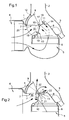
- Figure 1 We first refer to Figure 1 to describe a first embodiment of a heating device and / or air conditioning according to the invention for a vehicle automobile.
- the illustrated device comprises a treatment box and air distribution 1 for dispensing treated air in the passenger compartment of a motor vehicle, at the level of mouths (not shown), by through at least two distribution ducts 2 and 3.
- the first distribution duct 2 supplies dispensing vents placed in the dashboard vehicle and at the base of the windshield, while the second distribution duct 3 supplies dispensing outlets placed at the feet of the passengers.
- the housing 1 delimits a supply duct air flow cold 4 and a hot air supply duct 5 both fed with cold or recirculated air.
- the conduit hot air flow supply 5, also called heating duct, houses a heating radiator 6 traveled by a hot liquid, which is usually the liquid for cooling the engine of the vehicle.
- the housing 1 finally defines an air mixing chamber 7 communicating with the supply ducts 4 and 5 and with the first 2 and second 3 distribution ducts.
- a portion of a end portion of the heating pipe 5, placed downstream of the radiator 6, and a portion of an upstream portion of the second distribution duct 3 are delimited by a partition common 8.
- the housing 1 houses control means comprising of first 9, second 10 and third 11 flaps each provided with respective closure walls 12 to 14.
- control means comprising of first 9, second 10 and third 11 flaps each provided with respective closure walls 12 to 14.
- the first 9, second 10 and third 11 flaps are mounted swiveling around the same axis of rotation 15. They can thus be trained in rotation simultaneously and in the same direction to manage jointly the access of cold air flows and airflow hot in the mixing room 7.
- the mixing chamber 7 is subdivided into two parts called upstream 16 and downstream 17. Direct access to the upstream part 16 is controlled by the first 9 and second 10 shutters, and direct access to the downstream part 17 is controlled by the third component 11.
- the axis of rotation 15 is installed in the vicinity from the downstream end of the heating duct 5 so as to define two outputs 18 and 19 respectively controlled by the second 10 and third 11 shutters and opening respectively in the upstream 16 and downstream 17 parts of the chamber This allows you to define a section of heating up larger than in the devices of art prior.
- the axis of rotation 15 and therefore the flaps 9-11 can be rotated between a first position, materialized in solid lines, in which the closure wall 12 of the first flap 9 completely releases the output 20 of the feed duct in cold air flow 4 so that the flow of cold air can access the upstream part 16 of the chamber 7, while at the same time the walls shutter 13 and 14 of the second 10 and third 11 shutters completely obstruct the outputs 18 and 19 of the reheat, thus preventing access to the hot air flow to the mixing chamber 7 (closed position), and a second position, materialized in broken lines, in which the shutter wall 12 of the first shutter 9 completely obstructs the outlet 20 of the air flow supply duct cold 4 in order to prevent access from the cold air flow to the upstream part 16 of the mixing chamber 7, while in the same time the closing walls 13 and 14 of the second 10 and third 11 flaps completely release the exits 18 and 19 of the heating duct so that the hot air flow can enter the downstream part 16 via exit 18 and in the downstream part 17 via the outlet 19 (open position).
- each of the outputs 18 to 20 is partially obstructed, so that the upstream portion 16 is powered by cold air flow and hot air flow for mixing (or mixing) and that the downstream part 17 is supplied with air mixed from the upstream portion 16 and in airflow hot from exit 19 controlled by the third part 11.
- the first component 9 is of drum type, and the second 10 and third 11 flaps are flag type.
- the first 9, second 10 and third 11 advantageously an assembly that can be of monoblock type. But as a variant, this set can be subdivided into a first subset consisting of the first component 9 and of a second monobloc subassembly consisting of second 10 and third 11 flaps. In this variant, the second 10 and third 11 strands may also constitute a single flag-type pane.
- the respective shapes of the shutters 9-11 are chosen from way to precisely control the places where the different streams are injected into the mixing chamber 7. This is even more particularly the case of the third part 11 whose shape is preferentially chosen so as to allow the injection of part of the hot air flow at neighborhood of the entrance of the second distribution duct 3 when it is dedicated to the feet of the passengers. This allows effect of creating a positive temperature difference between hot air that feeds the distribution outlets feet and the warm air that feeds the other mouths of distribution.
- This first embodiment also makes it possible to facilitate the management of temperature stratification between different outlets.
- FIG. 2 This is a first variant of the first mode embodiment described above with reference to FIG. in which only the shape of the third flap 11 has been changed. Therefore, all that has been said for the first embodiment remains valid here.
- the third component 11 has a substantially flat portion 21 extended by a curved portion 22 facing the downstream portion 17. This allows to constrain in the second position, on the one hand, the part of the hot air flow that enters the part upstream 16 of the mixing chamber 7 by the exit 18 to direct to the first distribution duct 2, after have been deflected by rear faces of parts 21 and 22 third part 11, and on the other hand, the other part of flow of hot air entering the downstream part 17 of the mixing chamber 7 by the exit 19 to go towards the second distribution duct 3, after having been deflected and / or calibrated by the front face of the part 21 of the third part 11.
- This second embodiment therefore makes it possible to calibrate the hot air flows intended to feed the ducts of distribution 2 and 3, and to further facilitate the management of temperature stratification between the different mouths of distribution.
- FIG. 3 This is a second variant of the first mode embodiment described above with reference to FIG.
- the common partition 8 is terminated by an end portion 23 whose shape is chosen to control the flow of air hot, mixed air flow and cold air flow inside of the downstream part 17 of the mixing chamber 7, in particular when the means of control are placed in a intermediate position (materialized in broken lines).
- This third embodiment also makes it possible to calibrate the hot air flows intended to supply the ducts of distribution 2 and 3, and to facilitate the management of stratification of temperature between different mouths of distribution.
- FIG. 4 This is a third variant of the first embodiment described above with reference to FIG. 1, in which the shapes of the second 10 and third 11 shutters have been changed. Therefore, all that has been says for the first embodiment remains valid here.
- the second 10 and third 11 strands constitute at least one subset monobloc in the form of a butterfly flap 24 of the type illustrated, for example, in the figure 5. They can also constitute with the first part 9 a monobloc set.
- the butterfly flap 24 comprises a main wall 25 formed by the closing walls 13 and 14 and two side walls 26 and 27 secured to the main wall 25.
- the butterfly flap 24 thus defines a kind of channel.
- the channel formed from elements 25 to 27 substantially increases the section cold air passage, thus reducing the pressure losses and acoustic nuisances at the same rate.
- This embodiment also facilitates access to the airflow cold in the distribution duct 3, since the axis 15 does not come to annoy him anymore.
- the channel (formed of elements 25 to 27) promotes the rise of hot air towards the duct of distribution 2 and manages, ingeniously, the flow of flow of hot air to the distribution duct 3.
- This management is more precisely provided by a predetermined space, between the main wall 25 and the end 23 of the wall 8, which creates a calibrated leak.
- This fourth embodiment also makes it possible to facilitate the management of temperature stratification between different outlets, but it also allows to make less smooth the circuits borrowed by flows of hot air in the mixing chamber 7 in a mode of functioning said "foot mode" in which all the air treated feeds the second distribution duct 3.
- FIG. 6 a fifth embodiment of a heating device and / or air conditioning according to the invention, for a vehicle automobile.
- This fifth embodiment takes up a much of the elements constituting the first mode of embodiment described above with reference to FIG. Therefore, elements of the device of Figure 6 substantially identical to those of the device of FIG. carry identical references.
- the axes of rotation 15 and 29 can be driven in rotation in opposite directions as illustrated on the Figure 6, in the same direction.
- the first 9 and second 10 shutters, on the one hand, and the third component 28, on the other hand, have synchronized movements. But, they can open or close according to laws different, the third component 28 opening for example more or slower than the first 9 and second 10 flaps.
- the first 9 and second 10 shutters constitute a set that can be monobloc type.
- the end of the left side of the butterfly flap 28 comes into contact with the axis of rotation 15 when the means of control are in their first position.
- the housing 1 could have a partition portion allowing this end to come and lean against her.
- This fifth embodiment makes it possible to enlarge still plus the section of the heating duct 5, but also to inject two portions of hot air flow in two parts distinct from the downstream part 17 of the mixing chamber 7.
- a first portion is more particularly intended to feed the first distribution duct 2
- a second portion is more particularly intended to feed the second distribution duct 3.
- This fifth embodiment also makes it possible to facilitate the management of temperature stratification between different outlets, but it also allows to make less smooth the circuits borrowed by flows of hot air in the mixing chamber 7 in the feet mode supra.
- FIG. 7 describes a sixth embodiment of a heating device and / or air conditioning according to the invention for a motor vehicle. This is a variant of the fifth embodiment described above with reference to Figure 6, in which only the type of the third component 11 has been modified.
- the third component 30 is no longer butterfly type. He is now of type flag.
- its axis of rotation 31 is distant from the axis of rotation 15 which controls the joint move of the first 9 and second 10 shutters, which are always, and preferably, made in the form of drum flap and flag flap, respectively.
- the first 9 and second 10 shutters, on the one hand, and the third shutter 30, on the other hand, have synchronized movements. But, they can open or close according to laws different, the third component 30 opening for example more or slower than the first 9 and second 10 flaps.
- the axis of rotation 31 is here placed against the common partition 8 which, as in the third embodiment described previously with reference to FIG. 3, may comprise a shaped end portion to manage the flow and flow distribution in the downstream part 17 of the chamber of mixing 7.
- the axes of rotation 15 and 31 can be driven by rotation in the same direction as shown in the figure 7, in opposite directions.
- the first 9 and second 10 shutters constitute a set that can be monobloc type.
- the end of the left side of the (third) flag flap 30 comes into contact with the axis of rotation 15 when the control means are in their first position.
- the housing 1 could include a portion of partition allowing this end to come to lean against her.
- This sixth embodiment also makes it possible to facilitate the management of temperature stratification between different outlets.
- FIG. 8 This is a variant of the sixth mode of embodiment described above with reference to FIG. which only the third part 11 has been modified.
- the closure wall 14 of the third flap (flag type) 30 has a path of cam 32, here of linear type, in which can move a first axis of rotation 33.
- the wall shutter 13 of the second shutter 10 comprises a tab 34 on which is rotatably mounted a second axis of rotation 35.
- These first 33 and second 35 axes of rotation are secured to opposite ends of a rod 36, preferably rigid, which ensures the coupling of the second 10 and third 30 shutters.
- the rod 36 constrains the axis of rotation 31 to rotate in an opposite direction while the first axis 33 is translated into the cam path 32.
- the first 9 and second 10 strands constitute a set that may be of monobloc type.
- the end of the left side of the (third) flag flap 30 comes into contact with the axis of rotation 15 when the control means are in their first position.
- the housing 1 could include a portion of partition allowing this end to come to lean against her.
- This seventh embodiment also makes it possible to facilitate the management of temperature stratification between different outlets.
- FIG. 9 This is a variant of the seventh mode of embodiment described above with reference to FIG. 8.
- the latter (7) is formed on the bottom of the housing 1.
- This camming path 37 in which can be move the axis of rotation 31 of the third flap 30, is preferentially of linear form.
- the shutter wall 14 of the third flap (flag type) 30 has a tab 38 on which is rotatably mounted a first axis of rotation 33.
- the closure wall 13 of the second component 10 has a tab 34 on which is rotatably mounted a second axis of rotation 35.
- This first 33 and second 35 axes of rotation are integral with extremities opposite of a rod 36, preferably rigid, which ensures the coupling the second 10 and third 30 flaps. So, in driving in rotation in a selected direction the axis of rotation 15, the rod 36 constrains the axis of rotation 31 to rotate in an opposite direction and to translate in the cam path 37.
- the third component 30 thus constitutes a species of partition mobile that moves in the downstream part 17 of the chamber of mix 7 by gradually releasing an opening 39 which allows a part of the hot air flow, resulting from the opening 19, to join the second distribution duct 3, while that the other part of the hot air flow first joined the upstream part 16 via the opening 18, then the upper part from the downstream part 17 before entering the first distribution duct 2.
- the first 9 and second 10 strands constitute a set that may be of monobloc type.
- the end of the left side of the (third) flag flap 30 comes into contact with the axis of rotation 15 when the control means are in their first position.
- the housing 1 could include a portion of partition allowing this end to come to lean against her.
- This eighth embodiment also makes it easier to the management of temperature stratification between different outlets, but it also allows to make less smooth the circuits borrowed by flows of hot air in the mixing chamber 7 in the feet mode supra.
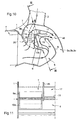
- FIG. 10 to 12 describe a ninth embodiment of a heating device and / or air conditioning according to the invention for a vehicle automobile.
- This ninth embodiment resumes the entirety of the elements constituting the first mode of embodiment described above with reference to FIG. What differentiates it is, on the one hand, the layouts of the mixing chamber 7 and the second pipe of distribution of air 3, and secondly, the presence of two first shutters 9a and 9b and two second shutters 10a and 10b.
- the mixing chamber 7 and the distribution duct 3 are subdivided by at least two partitions 45 into at least three subparts, for example two lateral and a central.
- the conduit of distribution 3 defines at least three subchannels 3a to 3c, as for example two lateral sub-ducts 3a and 3b between which (or in which) is placed (or inserted) a sub-conduit "central" 3c.
- This central sub-duct 3c is example dedicated to a particular area of the passenger compartment that requires a different temperature from those powered by the two lateral sub-ducts. This particular area can for example, the rear aeration zone, or the zone of feet back, or the area of the front feet.
- this central sub-duct 3c is preferentially fed by a mixing chamber auxiliary 46, independent, formed in the mixing chamber 7, in the vicinity of the inlet of the distribution duct 3.
- the management of access to the three sub-parts of the mixing chamber 7 and to the three air distribution sub-ducts 3a to 3c is here provided by two first drum-type flaps 9a and 9b, two second flag-like flaps 10a and 10b and one third flap type flag 11, mounted on the axis 15. More precisely, the first component 9a (respectively 9b) and the second component 10a (respectively 10b) constitute a together, possibly monobloc, of the type presented above with reference to FIG. 1. Each set (9a, 10a) and (9b, 10b) manages the access to the two lateral sub-parts of the mixing chamber 7 and the two sub-ducts lateral 3a and 3b.
- the third component 11 manages access to auxiliary mixing chamber 46 and therefore to the sub-duct central 3c, via exit 19.
- materialized in solid lines on the FIG. 10 shows part of the hot air flow coming from heating duct 5 directly feeds the chamber of auxiliary mix 46, while the complementary parts feed the two sub-parts of the mixing chamber 7.
- aerothermal in the auxiliary mixing chamber 46 is not the same as the one in the two sub-parts side of the mixing chamber 7.
- This ninth embodiment allows not only facilitate the management of temperature stratification between the different outlets, but it allows also optimize aerodynamic performance.
- auxiliary control means 40 comprise fourth 41 and fifth 42 shutters each provided with shutter walls 43 and 44 and mounted pivoting about the same axis of rotation 45 so as to be rotated simultaneously and in the same direction to jointly manage access to the first 2-1 and second 2-2 sub-conduits of a treated air stream from the downstream part 17 of the mixing chamber 7.
- the fifth component 42 is of type butterfly and the fourth drum-type flap.
- a fifth butterfly-type flap one could provide a fifth flap of flag type and a sixth flap type or butterfly, possibly mounted to rotation on an axis distant from the axis of rotation 45.
- auxiliary control means 40 can be arranged in substantially the same way as the means for control consisting of the first, second and third shutters, described above with reference to FIGS. 1 to 9.
- control auxiliary 40 can be implanted in the second conduit of distribution 3, when it is subdivided into two subducts.
- the invention is not limited to the embodiments of heating and / or air conditioning device described above, only as an example, but it encompasses all variants that may be considered by those skilled in the art of the claims below.
Landscapes
- Physics & Mathematics (AREA)
- Thermal Sciences (AREA)
- Engineering & Computer Science (AREA)
- Mechanical Engineering (AREA)
- Air-Conditioning For Vehicles (AREA)
- Devices For Blowing Cold Air, Devices For Blowing Warm Air, And Means For Preventing Water Condensation In Air Conditioning Units (AREA)
- Duct Arrangements (AREA)
- Air-Flow Control Members (AREA)
Applications Claiming Priority (2)
| Application Number | Priority Date | Filing Date | Title |
|---|---|---|---|
| FR0310751A FR2859665B1 (fr) | 2003-09-12 | 2003-09-12 | Dispositif de chauffage et/ou climatisation d'habitacle, a gestion aerothermique perfectionnee |
| FR0310751 | 2003-09-12 |
Publications (2)
| Publication Number | Publication Date |
|---|---|
| EP1514708A1 true EP1514708A1 (de) | 2005-03-16 |
| EP1514708B1 EP1514708B1 (de) | 2009-02-18 |
Family
ID=34130806
Family Applications (1)
| Application Number | Title | Priority Date | Filing Date |
|---|---|---|---|
| EP04019014A Expired - Lifetime EP1514708B1 (de) | 2003-09-12 | 2004-08-11 | Heiz und/oder Klimatiserungsvorrichtung für Fahrzeuginnenraum, mit hoch entwickelter aerothermischer Regelung |
Country Status (7)
| Country | Link |
|---|---|
| EP (1) | EP1514708B1 (de) |
| CN (1) | CN1593966A (de) |
| AT (1) | ATE423027T1 (de) |
| BR (1) | BRPI0403320A (de) |
| DE (1) | DE602004019480D1 (de) |
| ES (1) | ES2320216T3 (de) |
| FR (1) | FR2859665B1 (de) |
Cited By (6)
| Publication number | Priority date | Publication date | Assignee | Title |
|---|---|---|---|---|
| EP1726460A1 (de) * | 2005-05-25 | 2006-11-29 | VALEO AUTOKLIMATIZACE s.r.o. | Luftverteilervorrichtung mit Drehklappen mit voneinander abhängigen Drehbewegungen |
| US20100025011A1 (en) * | 2007-03-08 | 2010-02-04 | Mitsubishi Heavy Industries, Ltd. | Vehicle air conditioner |
| EP2218596A1 (de) * | 2009-02-17 | 2010-08-18 | Behr France Rouffach SAS | Fahrzeug-Klimaanlage mit Kühlanordnung für ein Handschuhfach |
| WO2012120047A1 (de) * | 2011-03-07 | 2012-09-13 | Behr Gmbh & Co. Kg | Luftumlenkelement mit einer strömungsoptimierten kontur für eine klimaanlage |
| US20180312030A1 (en) * | 2016-04-22 | 2018-11-01 | Hanon Systems | Air conditioner for vehicle |
| DE102014105115B4 (de) | 2014-04-10 | 2024-12-12 | Hanon Systems | Luftleiteinrichtung einer Klimatisierungsvorrichtung eines Kraftfahrzeugs |
Families Citing this family (1)
| Publication number | Priority date | Publication date | Assignee | Title |
|---|---|---|---|---|
| CN103939982A (zh) * | 2013-01-21 | 2014-07-23 | 凌泽民 | 汽车空调器 |
Citations (6)
| Publication number | Priority date | Publication date | Assignee | Title |
|---|---|---|---|---|
| US4947735A (en) * | 1988-05-27 | 1990-08-14 | Valeo | Distribution box for a heating and/or air conditioning apparatus, especially for an automotive vehicle |
| DE19800103A1 (de) * | 1997-01-07 | 1998-07-09 | Denso Corp | Klimaanlage für ein Fahrzeug |
| EP0909669A1 (de) * | 1997-10-14 | 1999-04-21 | Valeo Climatisation | Luftbehandlungsgehäuse mit verbesserter Temperaturverwaltung, für eine Heizungs- und/oder Klimaanlage, insbesondere für Kraftfahrzeuge |
| US5967890A (en) * | 1996-06-14 | 1999-10-19 | Valeo Climatisation | Heating and ventilating apparatus for the cabin of a motor vehicle |
| FR2786134A1 (fr) * | 1998-11-19 | 2000-05-26 | Valeo Climatisation | Dispositif de chauffage-ventilation de l'habitacle d'un vehicule |
| FR2787393A1 (fr) | 1998-12-22 | 2000-06-23 | Valeo Climatisation | Dispositif de chauffage et/ou climatisation de vehicule automobile a mixage d'air ameliore |
-
2003
- 2003-09-12 FR FR0310751A patent/FR2859665B1/fr not_active Expired - Fee Related
-
2004
- 2004-08-11 ES ES04019014T patent/ES2320216T3/es not_active Expired - Lifetime
- 2004-08-11 DE DE602004019480T patent/DE602004019480D1/de not_active Expired - Lifetime
- 2004-08-11 EP EP04019014A patent/EP1514708B1/de not_active Expired - Lifetime
- 2004-08-11 AT AT04019014T patent/ATE423027T1/de not_active IP Right Cessation
- 2004-08-19 BR BR0403320-5A patent/BRPI0403320A/pt not_active IP Right Cessation
- 2004-09-10 CN CN200410077139.2A patent/CN1593966A/zh active Pending
Patent Citations (6)
| Publication number | Priority date | Publication date | Assignee | Title |
|---|---|---|---|---|
| US4947735A (en) * | 1988-05-27 | 1990-08-14 | Valeo | Distribution box for a heating and/or air conditioning apparatus, especially for an automotive vehicle |
| US5967890A (en) * | 1996-06-14 | 1999-10-19 | Valeo Climatisation | Heating and ventilating apparatus for the cabin of a motor vehicle |
| DE19800103A1 (de) * | 1997-01-07 | 1998-07-09 | Denso Corp | Klimaanlage für ein Fahrzeug |
| EP0909669A1 (de) * | 1997-10-14 | 1999-04-21 | Valeo Climatisation | Luftbehandlungsgehäuse mit verbesserter Temperaturverwaltung, für eine Heizungs- und/oder Klimaanlage, insbesondere für Kraftfahrzeuge |
| FR2786134A1 (fr) * | 1998-11-19 | 2000-05-26 | Valeo Climatisation | Dispositif de chauffage-ventilation de l'habitacle d'un vehicule |
| FR2787393A1 (fr) | 1998-12-22 | 2000-06-23 | Valeo Climatisation | Dispositif de chauffage et/ou climatisation de vehicule automobile a mixage d'air ameliore |
Cited By (11)
| Publication number | Priority date | Publication date | Assignee | Title |
|---|---|---|---|---|
| EP1726460A1 (de) * | 2005-05-25 | 2006-11-29 | VALEO AUTOKLIMATIZACE s.r.o. | Luftverteilervorrichtung mit Drehklappen mit voneinander abhängigen Drehbewegungen |
| US20100025011A1 (en) * | 2007-03-08 | 2010-02-04 | Mitsubishi Heavy Industries, Ltd. | Vehicle air conditioner |
| EP2133222A4 (de) * | 2007-03-08 | 2011-10-19 | Mitsubishi Heavy Ind Ltd | Fahrzeugklimaanlage |
| US8540014B2 (en) | 2007-03-08 | 2013-09-24 | Mitsubishi Heavy Industries, Ltd. | Vehicle air conditioner |
| EP2218596A1 (de) * | 2009-02-17 | 2010-08-18 | Behr France Rouffach SAS | Fahrzeug-Klimaanlage mit Kühlanordnung für ein Handschuhfach |
| WO2012120047A1 (de) * | 2011-03-07 | 2012-09-13 | Behr Gmbh & Co. Kg | Luftumlenkelement mit einer strömungsoptimierten kontur für eine klimaanlage |
| US9533548B2 (en) | 2011-03-07 | 2017-01-03 | Mahle International Gmbh | Air-diverting element with a flow-optimized contour for an air-conditioning system |
| DE102014105115B4 (de) | 2014-04-10 | 2024-12-12 | Hanon Systems | Luftleiteinrichtung einer Klimatisierungsvorrichtung eines Kraftfahrzeugs |
| DE102014105115B8 (de) | 2014-04-10 | 2025-04-30 | Hanon Systems | Luftleiteinrichtung einer Klimatisierungsvorrichtung eines Kraftfahrzeugs |
| US20180312030A1 (en) * | 2016-04-22 | 2018-11-01 | Hanon Systems | Air conditioner for vehicle |
| US10538142B2 (en) * | 2016-04-22 | 2020-01-21 | Hanon Systems | Air conditioner for vehicle |
Also Published As
| Publication number | Publication date |
|---|---|
| DE602004019480D1 (de) | 2009-04-02 |
| EP1514708B1 (de) | 2009-02-18 |
| ATE423027T1 (de) | 2009-03-15 |
| ES2320216T3 (es) | 2009-05-20 |
| BRPI0403320A (pt) | 2005-05-31 |
| FR2859665B1 (fr) | 2006-02-10 |
| CN1593966A (zh) | 2005-03-16 |
| FR2859665A1 (fr) | 2005-03-18 |
Similar Documents
| Publication | Publication Date | Title |
|---|---|---|
| EP0936090B1 (de) | Heiz- und/oder Klimatisierungsvorrichtung eines Kraftfahrzeuges mit verbessertem Wärmetausch-Management | |
| EP1514707B1 (de) | Verbesserte Lufttemperatursteuerung einer Heiz- und/oder Klimaanlage einer Fahrgastzelle | |
| EP2889168B1 (de) | Vorrichtung zum Heizen, Belüften und/oder Klimatisieren | |
| FR2703304A1 (fr) | Boîtier de distribution pour une installation de chauffage-ventilation de l'habitacle d'un véhicule automobile. | |
| EP0266230A1 (de) | Mischklappe für Fahrzeugklimaanlagen und ähnliche Anwendungen | |
| EP1254794A1 (de) | Anlage zur Wiederverwendung von Luft aus dem Fahrzeug-Innenraum | |
| EP0812714B1 (de) | Vorrichtung für die Heizung und/oder Lüftung eines Fahrzeuginnenraumes | |
| EP1514708B1 (de) | Heiz und/oder Klimatiserungsvorrichtung für Fahrzeuginnenraum, mit hoch entwickelter aerothermischer Regelung | |
| EP1242258B1 (de) | Luftleitkasten | |
| EP0780251B1 (de) | Vorrichtung für die Heizung, Lüftung und/oder Klimatisierung, insbesondere für Kraftwagen | |
| EP1473449B1 (de) | Vorrichtung zur Steuerung des Luftstromes für ein Kühlmodul eines Kraftfahrzeugs | |
| WO2020174146A1 (fr) | Installation de chauffage et/ou ventilation et/ou climatisation comportant un volet de mixage avec déflecteur | |
| EP1387774B2 (de) | Luftleitkasten | |
| EP1240040B1 (de) | Heizungs-, belüftungs- und/oder klimaanlagen | |
| FR2929558A1 (fr) | Organe de mixage d'air du type volet-tambour et installation de chauffage, de ventilation et/ou de climatisation equipee d'un tel organe de mixage d'air. | |
| FR2765526A1 (fr) | Installation de chauffage et/ou climatisation, notamment de vehicule automobile, equipee d'un boitier de traitement d'air a distribution d'air perfectionne | |
| FR2795684A1 (fr) | Dispositif perfectionne de chauffage, ventilation et/ou climatisation d'un habitacle, notamment de vehicule automobile, a reglage de temperature par zones | |
| FR2746714A1 (fr) | Dispositif de chauffage et/ou climatisation de l'habitacle d'un vehicule automobile | |
| FR2795683A1 (fr) | Dispositif de chauffage et/ou climatisation d'un habitacle, notamment de vehicule automobile, a conduit transversal | |
| FR2778151A1 (fr) | Dispositif repartiteur d'un flux d'air dans un habitacle, notamment d'un vehicule automobile | |
| FR2698589A1 (fr) | Dispositif de chauffage-ventilation et/ou de climatisation de l'habitacle d'un véhicule automobile. | |
| FR2590848A3 (fr) | Dispositif de brassage de l'air destine aux installations de ventilation de l'habitacle de voitures automobiles avec possibilite d'interdire, selectivement, l'afflux de l'air de ventilation | |
| EP2240338B1 (de) | Einzelklappe für den verschluss des mittel- und seitenluftaustritts bei einem insassenraumklimatisierungssystem eines kraftfahrzeuges | |
| FR2786134A1 (fr) | Dispositif de chauffage-ventilation de l'habitacle d'un vehicule | |
| EP1405743B1 (de) | Vorrichtung zur Heizung und/oder Klimatisierung eines Fahrzeuginnenraumes mit reduziertem Druckverlust |
Legal Events
| Date | Code | Title | Description |
|---|---|---|---|
| PUAI | Public reference made under article 153(3) epc to a published international application that has entered the european phase |
Free format text: ORIGINAL CODE: 0009012 |
|
| AK | Designated contracting states |
Kind code of ref document: A1 Designated state(s): AT BE BG CH CY CZ DE DK EE ES FI FR GB GR HU IE IT LI LU MC NL PL PT RO SE SI SK TR |
|
| AX | Request for extension of the european patent |
Extension state: AL HR LT LV MK |
|
| 17P | Request for examination filed |
Effective date: 20050805 |
|
| RAP1 | Party data changed (applicant data changed or rights of an application transferred) |
Owner name: VALEO SYSTEMES THERMIQUES |
|
| AKX | Designation fees paid |
Designated state(s): AT BE BG CH CY CZ DE DK EE ES FI FR GB GR HU IE IT LI LU MC NL PL PT RO SE SI SK TR |
|
| GRAP | Despatch of communication of intention to grant a patent |
Free format text: ORIGINAL CODE: EPIDOSNIGR1 |
|
| GRAS | Grant fee paid |
Free format text: ORIGINAL CODE: EPIDOSNIGR3 |
|
| GRAA | (expected) grant |
Free format text: ORIGINAL CODE: 0009210 |
|
| AK | Designated contracting states |
Kind code of ref document: B1 Designated state(s): AT BE BG CH CY CZ DE DK EE ES FI FR GB GR HU IE IT LI LU MC NL PL PT RO SE SI SK TR |
|
| REG | Reference to a national code |
Ref country code: GB Ref legal event code: FG4D Free format text: NOT ENGLISH |
|
| REG | Reference to a national code |
Ref country code: CH Ref legal event code: EP |
|
| REG | Reference to a national code |
Ref country code: IE Ref legal event code: FG4D Free format text: LANGUAGE OF EP DOCUMENT: FRENCH |
|
| REF | Corresponds to: |
Ref document number: 602004019480 Country of ref document: DE Date of ref document: 20090402 Kind code of ref document: P |
|
| REG | Reference to a national code |
Ref country code: ES Ref legal event code: FG2A Ref document number: 2320216 Country of ref document: ES Kind code of ref document: T3 |
|
| PG25 | Lapsed in a contracting state [announced via postgrant information from national office to epo] |
Ref country code: NL Free format text: LAPSE BECAUSE OF FAILURE TO SUBMIT A TRANSLATION OF THE DESCRIPTION OR TO PAY THE FEE WITHIN THE PRESCRIBED TIME-LIMIT Effective date: 20090218 Ref country code: SI Free format text: LAPSE BECAUSE OF FAILURE TO SUBMIT A TRANSLATION OF THE DESCRIPTION OR TO PAY THE FEE WITHIN THE PRESCRIBED TIME-LIMIT Effective date: 20090218 Ref country code: FI Free format text: LAPSE BECAUSE OF FAILURE TO SUBMIT A TRANSLATION OF THE DESCRIPTION OR TO PAY THE FEE WITHIN THE PRESCRIBED TIME-LIMIT Effective date: 20090218 |
|
| NLV1 | Nl: lapsed or annulled due to failure to fulfill the requirements of art. 29p and 29m of the patents act | ||
| PG25 | Lapsed in a contracting state [announced via postgrant information from national office to epo] |
Ref country code: SE Free format text: LAPSE BECAUSE OF FAILURE TO SUBMIT A TRANSLATION OF THE DESCRIPTION OR TO PAY THE FEE WITHIN THE PRESCRIBED TIME-LIMIT Effective date: 20090518 Ref country code: PL Free format text: LAPSE BECAUSE OF FAILURE TO SUBMIT A TRANSLATION OF THE DESCRIPTION OR TO PAY THE FEE WITHIN THE PRESCRIBED TIME-LIMIT Effective date: 20090218 Ref country code: AT Free format text: LAPSE BECAUSE OF FAILURE TO SUBMIT A TRANSLATION OF THE DESCRIPTION OR TO PAY THE FEE WITHIN THE PRESCRIBED TIME-LIMIT Effective date: 20090218 |
|
| REG | Reference to a national code |
Ref country code: IE Ref legal event code: FD4D |
|
| PG25 | Lapsed in a contracting state [announced via postgrant information from national office to epo] |
Ref country code: IE Free format text: LAPSE BECAUSE OF FAILURE TO SUBMIT A TRANSLATION OF THE DESCRIPTION OR TO PAY THE FEE WITHIN THE PRESCRIBED TIME-LIMIT Effective date: 20090218 Ref country code: DK Free format text: LAPSE BECAUSE OF FAILURE TO SUBMIT A TRANSLATION OF THE DESCRIPTION OR TO PAY THE FEE WITHIN THE PRESCRIBED TIME-LIMIT Effective date: 20090218 Ref country code: EE Free format text: LAPSE BECAUSE OF FAILURE TO SUBMIT A TRANSLATION OF THE DESCRIPTION OR TO PAY THE FEE WITHIN THE PRESCRIBED TIME-LIMIT Effective date: 20090218 Ref country code: PT Free format text: LAPSE BECAUSE OF FAILURE TO SUBMIT A TRANSLATION OF THE DESCRIPTION OR TO PAY THE FEE WITHIN THE PRESCRIBED TIME-LIMIT Effective date: 20090727 |
|
| PG25 | Lapsed in a contracting state [announced via postgrant information from national office to epo] |
Ref country code: SK Free format text: LAPSE BECAUSE OF FAILURE TO SUBMIT A TRANSLATION OF THE DESCRIPTION OR TO PAY THE FEE WITHIN THE PRESCRIBED TIME-LIMIT Effective date: 20090218 Ref country code: RO Free format text: LAPSE BECAUSE OF FAILURE TO SUBMIT A TRANSLATION OF THE DESCRIPTION OR TO PAY THE FEE WITHIN THE PRESCRIBED TIME-LIMIT Effective date: 20090218 |
|
| PLBE | No opposition filed within time limit |
Free format text: ORIGINAL CODE: 0009261 |
|
| STAA | Information on the status of an ep patent application or granted ep patent |
Free format text: STATUS: NO OPPOSITION FILED WITHIN TIME LIMIT |
|
| 26N | No opposition filed |
Effective date: 20091119 |
|
| PG25 | Lapsed in a contracting state [announced via postgrant information from national office to epo] |
Ref country code: BG Free format text: LAPSE BECAUSE OF FAILURE TO SUBMIT A TRANSLATION OF THE DESCRIPTION OR TO PAY THE FEE WITHIN THE PRESCRIBED TIME-LIMIT Effective date: 20090518 |
|
| BERE | Be: lapsed |
Owner name: VALEO SYSTEMES THERMIQUES Effective date: 20090831 |
|
| PG25 | Lapsed in a contracting state [announced via postgrant information from national office to epo] |
Ref country code: MC Free format text: LAPSE BECAUSE OF NON-PAYMENT OF DUE FEES Effective date: 20090831 |
|
| REG | Reference to a national code |
Ref country code: CH Ref legal event code: PL |
|
| PG25 | Lapsed in a contracting state [announced via postgrant information from national office to epo] |
Ref country code: CH Free format text: LAPSE BECAUSE OF NON-PAYMENT OF DUE FEES Effective date: 20090831 Ref country code: LI Free format text: LAPSE BECAUSE OF NON-PAYMENT OF DUE FEES Effective date: 20090831 |
|
| PG25 | Lapsed in a contracting state [announced via postgrant information from national office to epo] |
Ref country code: BE Free format text: LAPSE BECAUSE OF NON-PAYMENT OF DUE FEES Effective date: 20090831 |
|
| PG25 | Lapsed in a contracting state [announced via postgrant information from national office to epo] |
Ref country code: GR Free format text: LAPSE BECAUSE OF FAILURE TO SUBMIT A TRANSLATION OF THE DESCRIPTION OR TO PAY THE FEE WITHIN THE PRESCRIBED TIME-LIMIT Effective date: 20090519 |
|
| PG25 | Lapsed in a contracting state [announced via postgrant information from national office to epo] |
Ref country code: LU Free format text: LAPSE BECAUSE OF NON-PAYMENT OF DUE FEES Effective date: 20090811 |
|
| PG25 | Lapsed in a contracting state [announced via postgrant information from national office to epo] |
Ref country code: HU Free format text: LAPSE BECAUSE OF FAILURE TO SUBMIT A TRANSLATION OF THE DESCRIPTION OR TO PAY THE FEE WITHIN THE PRESCRIBED TIME-LIMIT Effective date: 20090819 |
|
| PG25 | Lapsed in a contracting state [announced via postgrant information from national office to epo] |
Ref country code: TR Free format text: LAPSE BECAUSE OF FAILURE TO SUBMIT A TRANSLATION OF THE DESCRIPTION OR TO PAY THE FEE WITHIN THE PRESCRIBED TIME-LIMIT Effective date: 20090218 |
|
| PG25 | Lapsed in a contracting state [announced via postgrant information from national office to epo] |
Ref country code: CY Free format text: LAPSE BECAUSE OF FAILURE TO SUBMIT A TRANSLATION OF THE DESCRIPTION OR TO PAY THE FEE WITHIN THE PRESCRIBED TIME-LIMIT Effective date: 20090218 |
|
| PGFP | Annual fee paid to national office [announced via postgrant information from national office to epo] |
Ref country code: GB Payment date: 20130816 Year of fee payment: 10 Ref country code: FR Payment date: 20130902 Year of fee payment: 10 |
|
| PGFP | Annual fee paid to national office [announced via postgrant information from national office to epo] |
Ref country code: CZ Payment date: 20140721 Year of fee payment: 11 Ref country code: DE Payment date: 20140812 Year of fee payment: 11 |
|
| PGFP | Annual fee paid to national office [announced via postgrant information from national office to epo] |
Ref country code: ES Payment date: 20140820 Year of fee payment: 11 |
|
| PGFP | Annual fee paid to national office [announced via postgrant information from national office to epo] |
Ref country code: IT Payment date: 20140808 Year of fee payment: 11 |
|
| GBPC | Gb: european patent ceased through non-payment of renewal fee |
Effective date: 20140811 |
|
| REG | Reference to a national code |
Ref country code: FR Ref legal event code: ST Effective date: 20150430 |
|
| PG25 | Lapsed in a contracting state [announced via postgrant information from national office to epo] |
Ref country code: GB Free format text: LAPSE BECAUSE OF NON-PAYMENT OF DUE FEES Effective date: 20140811 |
|
| PG25 | Lapsed in a contracting state [announced via postgrant information from national office to epo] |
Ref country code: FR Free format text: LAPSE BECAUSE OF NON-PAYMENT OF DUE FEES Effective date: 20140901 |
|
| REG | Reference to a national code |
Ref country code: DE Ref legal event code: R119 Ref document number: 602004019480 Country of ref document: DE |
|
| PG25 | Lapsed in a contracting state [announced via postgrant information from national office to epo] |
Ref country code: IT Free format text: LAPSE BECAUSE OF NON-PAYMENT OF DUE FEES Effective date: 20150811 Ref country code: CZ Free format text: LAPSE BECAUSE OF NON-PAYMENT OF DUE FEES Effective date: 20150811 |
|
| PG25 | Lapsed in a contracting state [announced via postgrant information from national office to epo] |
Ref country code: DE Free format text: LAPSE BECAUSE OF NON-PAYMENT OF DUE FEES Effective date: 20160301 |
|
| REG | Reference to a national code |
Ref country code: ES Ref legal event code: FD2A Effective date: 20160927 |
|
| PG25 | Lapsed in a contracting state [announced via postgrant information from national office to epo] |
Ref country code: ES Free format text: LAPSE BECAUSE OF NON-PAYMENT OF DUE FEES Effective date: 20150812 |