EP0909834A2 - Dispositif pour transport des feuilles - Google Patents
Dispositif pour transport des feuilles Download PDFInfo
- Publication number
- EP0909834A2 EP0909834A2 EP98116742A EP98116742A EP0909834A2 EP 0909834 A2 EP0909834 A2 EP 0909834A2 EP 98116742 A EP98116742 A EP 98116742A EP 98116742 A EP98116742 A EP 98116742A EP 0909834 A2 EP0909834 A2 EP 0909834A2
- Authority
- EP
- European Patent Office
- Prior art keywords
- transport roller
- film
- transport
- opening
- transported
- Prior art date
- Legal status (The legal status is an assumption and is not a legal conclusion. Google has not performed a legal analysis and makes no representation as to the accuracy of the status listed.)
- Withdrawn
Links
Images

Classifications
-
- C—CHEMISTRY; METALLURGY
- C23—COATING METALLIC MATERIAL; COATING MATERIAL WITH METALLIC MATERIAL; CHEMICAL SURFACE TREATMENT; DIFFUSION TREATMENT OF METALLIC MATERIAL; COATING BY VACUUM EVAPORATION, BY SPUTTERING, BY ION IMPLANTATION OR BY CHEMICAL VAPOUR DEPOSITION, IN GENERAL; INHIBITING CORROSION OF METALLIC MATERIAL OR INCRUSTATION IN GENERAL
- C23C—COATING METALLIC MATERIAL; COATING MATERIAL WITH METALLIC MATERIAL; SURFACE TREATMENT OF METALLIC MATERIAL BY DIFFUSION INTO THE SURFACE, BY CHEMICAL CONVERSION OR SUBSTITUTION; COATING BY VACUUM EVAPORATION, BY SPUTTERING, BY ION IMPLANTATION OR BY CHEMICAL VAPOUR DEPOSITION, IN GENERAL
- C23C14/00—Coating by vacuum evaporation, by sputtering or by ion implantation of the coating forming material
- C23C14/22—Coating by vacuum evaporation, by sputtering or by ion implantation of the coating forming material characterised by the process of coating
- C23C14/54—Controlling or regulating the coating process
- C23C14/541—Heating or cooling of the substrates
-
- B—PERFORMING OPERATIONS; TRANSPORTING
- B65—CONVEYING; PACKING; STORING; HANDLING THIN OR FILAMENTARY MATERIAL
- B65H—HANDLING THIN OR FILAMENTARY MATERIAL, e.g. SHEETS, WEBS, CABLES
- B65H23/00—Registering, tensioning, smoothing or guiding webs
- B65H23/02—Registering, tensioning, smoothing or guiding webs transversely
Definitions
- the invention relates to a film transport device according to the preamble of the claim 1 and the use of the film transport device according to the invention according to claim 12.
- Such film feeders are known Way also in so-called coil coating plants, such as B. described in EP 406 641 A1, used.
- these coating systems e.g. B. for the production of ribbon capacitor films a thin metallic layer, e.g. B. aluminum, on the continuously via evaporator boats guided film sheet evaporated.
- a thin metallic layer e.g. B. aluminum
- the unwinding roll, the film feeders and the take-up roll during the coating process arranged within the coil coating system. The unwinding and winding roll will be only after the entire film web has been coated removed from the vacuum chamber or against new winding rolls exchanged.
- the object of the present invention is a To design a device for transporting film webs that the supply and the further transport the film from a supply roll to one Processing station and further to a take-up roll is made possible in a simple manner, wherein the disadvantages of batch processing, in particular State of the art coating be avoided.
- this object is achieved by that in a device for transporting foils, especially of film webs, a fixed, preferably a circular cross section having transport roller is provided, on the lateral surface of the film to be transported abuts and on this or a conveyor belt slides snugly with the feed direction the film web lying on the outer surface an angle with the axis of the transport roller forms ⁇ ⁇ 0 ° or ⁇ ⁇ 90 °.
- the direction of advance of the film through the direction the axis of the transport roller.
- the transport path of the film is proportional for the axial extension of the on the transport roller adjacent winding sections.
- the film by means of transport elements, such as Bands, chains, straps or one already on Foil, helical over the outer surface to pull the transport roller.
- transport elements such as Bands, chains, straps or one already on Foil
- Conveyor belts are provided because of the coefficient of friction between the preferably also made of metallic Shell surface made of materials the transport roller and a metallic conveyor belt is low, which means only low tensile forces necessary for the axial feed of the conveyor belt are.
- the materials Shell surface and the conveyor belt also others Suitable material combinations, which have a low Allow coefficients of friction.
- the conveyor belt this is done from one end of the transport roller to their other end by means of appropriate Deflected elements and thus forms one closed ring.
- the film lying on the conveyor belt is then held on this by static friction.
- the effective length of the transport route is in essentially by the axial extent and the Number of wraps of the film around the transport roller selectable.
- the free overall cross section between the sliding, on the Lateral surface adjacent film and the free To measure the diameter of the opening such that an annular gap seal between the opening cross-section and film web is formed.
- This Annular gap seal is advantageous because of this the flow conductance through the free total cross section is reduced, which in particular Differences in pressure between the first and the second Half space can be maintained since a sufficient pressure equalization flow for this is prevented through the opening.
- the film e.g. from an atmospheric pressure Outside in a coating chamber having negative pressure into a coil coating line and the coated film web from the coating chamber out into the outside space, e.g. for the purpose of Rewinding on a take-up reel in continuous operation to transport.
- This is advantageous a continuous coating of long film webs possible, making their production inexpensive is.
- Are particularly suitable for this e.g. B. made of plastic and / or paper Film webs as claimed in claim 10.
- the opening form at least one groove over a Pumping channel through a pumping device, preferably by means of one or more vacuum pumps is evacuable.
- the z. B. trained as an annular groove The groove then forms an intermediate pumping stage between the higher pressure range and the negative pressure range in the coating chamber which is the transition of gas particles from the outside into the coating chamber prevented.
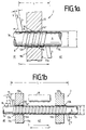
- Fig. 1a is one in an opening 12a Chamber wall 10 arranged transport roller 6 with wound film 4 shown.
- the Transport roller 6 protrudes on both sides of the chamber wall 10a in the half space 41 or 42.
- On the lateral surface 8 of the transport roller 6 is a film web 4 wound with several turns 14, 14 ', 14' '.
- the feed direction V of the film web 4 forms the axis A of the transport roller 6 a feed angle ⁇ , where ⁇ ⁇ 0 ° and ⁇ ⁇ 90 °.
- the feed angle ⁇ depending on the film web width a to be chosen so that the condition ⁇ ⁇ arctan (2 ⁇ r / a) is satisfied with 0 ° ⁇ ⁇ 90 °, the radius of the Transport roller is designated with r.
- the partition walls 10a, 10b shown in Fig. 1b are part of the chamber wall of a coil coating system with an evaporator source 18 for vacuum vapor deposition of foil webs 4 with metallic layers or metal oxides and / or nitrites, not completely shown in Fig. 1b.
- a film web 4 typically having a film thickness of 0.3 ⁇ m to 2 mm, it is transported from the outside space 41, which usually has atmospheric pressure, on the transport roller 6 through the opening 12a, 12b into the coating chamber 42 arranged in the strip coating system.
- the coating chamber 42 typically has a pressure of 10 -4 mbar to 10 -2 mbar during the coating process.
- annular gap 16a, 16b is formed such that the flow of atmospheric particles from the outer space 41 into the negative pressure area of the chamber 42 is prevented.
- the length of the entire transport path L of the film web 4 is proportional to the number of turns 14, 14 ', 14' 'on the transport roller 6.
- Film web 4 is either separated by two Transport rollers in a coating chamber transported in and out or through a only transport roller 6, as shown in Fig. 1b, into the coating chamber and at one Evaporator source 18 passed and then from the coating chamber 42 into the outer space 41 transported out and then usually up a take-up reel.
- the transport direction T, T 'of the film web 4 is by reversing the belt tension or the conveyor belt movement reversible.
- the transport roller 26 shown in Figure 2 is like the transport roller 6 in Figure 1a or 1b in the opening 32 of a partition 30 is arranged.
- the Partition 30 does not separate interior 20 coating chamber shown by the Outside space 21.
- FIG Film feed direction V ' guides the transport roller 26 the film web 24 from the atmospheric pressure Outside space 21 in the negative pressure Coating chamber 20.
- an annular gap 36 is formed, the function a vacuum seal between the outside 21 and the interior 20 of the coating chamber.
- Vacuum pump can be evacuated to negative pressure is.
- the evacuable groove 38 forms an intermediate the outside space 21 and the inside 21 of the coating chamber arranged intermediate pump stage for Separation of the atmospheric area 21 from the vacuum area 20. Further evacuable intermediate pump stages can be provided in the area of the opening 32 become. The number of intermediate pump stages depending on the space between the 21st and the coating chamber 20 existing printing difference to choose such that a pressure increase in the coating chamber 20 during the Transport and coating the film web 24 is avoided.
- the film transport device shown in Figure 2 22 with intermediate pump stage is also for The coated film web 24 is discharged the interior 20 of the coating system in a corresponding manner Application provided.
Landscapes
- Chemical & Material Sciences (AREA)
- Chemical Kinetics & Catalysis (AREA)
- Engineering & Computer Science (AREA)
- Materials Engineering (AREA)
- Mechanical Engineering (AREA)
- Metallurgy (AREA)
- Organic Chemistry (AREA)
- Physical Vapour Deposition (AREA)
- Advancing Webs (AREA)
Applications Claiming Priority (2)
| Application Number | Priority Date | Filing Date | Title |
|---|---|---|---|
| DE1997139833 DE19739833A1 (de) | 1997-09-11 | 1997-09-11 | Folientransportvorrichtung |
| DE19739833 | 1997-09-11 |
Publications (2)
| Publication Number | Publication Date |
|---|---|
| EP0909834A2 true EP0909834A2 (fr) | 1999-04-21 |
| EP0909834A3 EP0909834A3 (fr) | 1999-05-19 |
Family
ID=7841938
Family Applications (1)
| Application Number | Title | Priority Date | Filing Date |
|---|---|---|---|
| EP98116742A Withdrawn EP0909834A3 (fr) | 1997-09-11 | 1998-09-04 | Dispositif pour transport des feuilles |
Country Status (2)
| Country | Link |
|---|---|
| EP (1) | EP0909834A3 (fr) |
| DE (1) | DE19739833A1 (fr) |
Families Citing this family (2)
| Publication number | Priority date | Publication date | Assignee | Title |
|---|---|---|---|---|
| PT1347077E (pt) * | 2002-03-15 | 2006-09-29 | Vhf Technologies Sa | Aparelho e metodo para a producao de dispositivos semicondutores flexiveis |
| DE102005058869A1 (de) * | 2005-12-09 | 2007-06-14 | Cis Solartechnik Gmbh & Co. Kg | Verfahren und Vorrichtung zur Beschichtung von Bändern |
Family Cites Families (7)
| Publication number | Priority date | Publication date | Assignee | Title |
|---|---|---|---|---|
| DE1410800A1 (de) * | 1961-01-31 | 1968-10-17 | Artos Meier Windhorst Kg | Umlenkvorrichtung fuer Warenbahnen |
| GB1468358A (en) * | 1973-10-04 | 1977-03-23 | Ici Ltd | Seal |
| JPS61119673A (ja) * | 1984-11-15 | 1986-06-06 | Anelva Corp | 連続式金属薄膜製造装置 |
| DE3738722C2 (de) * | 1987-11-14 | 1995-12-14 | Leybold Ag | Vorrichtung zum beidseitigen Beschichten von Bändern |
| DE3922187A1 (de) * | 1989-07-06 | 1991-01-17 | Leybold Ag | Vorrichtung zum herstellen von metallfreien streifen bei im vakuum beschichteten folienbahnen, insbesondere fuer kondensatoren |
| US5016801A (en) * | 1990-08-28 | 1991-05-21 | Industrial Label Corporation | Multiple-ply web registration apparatus |
| JPH0768622B2 (ja) * | 1991-07-02 | 1995-07-26 | 中外炉工業株式会社 | 連続式真空処理装置のシール装置 |
-
1997
- 1997-09-11 DE DE1997139833 patent/DE19739833A1/de not_active Withdrawn
-
1998
- 1998-09-04 EP EP98116742A patent/EP0909834A3/fr not_active Withdrawn
Also Published As
| Publication number | Publication date |
|---|---|
| DE19739833A1 (de) | 1999-03-18 |
| EP0909834A3 (fr) | 1999-05-19 |
Similar Documents
| Publication | Publication Date | Title |
|---|---|---|
| DE3625221C2 (de) | Vorrichtung zum Aufwickeln eines Magnetbandes auf einen Aufwickelkern | |
| DE3913131C2 (fr) | ||
| DE202019102057U1 (de) | Doppelseitige Vakuumbeschichtungsvorrichtung zum kontinuierlichen Vorwärts- und Rückwärtsbeschichten eines Films | |
| EP3802910B1 (fr) | Installation de revêtement sous vide et procédé pour munir un matériau en forme de bande d'un revêtement | |
| DE2262148A1 (de) | Verfahren und vorrichtung zur zwischenspeicherung von bandfoermigen materialien, insbesondere metallband, in kontinuierlichen bandzufuehrungen zu verarbeitungsmaschinen | |
| EP0771643B1 (fr) | Procédé et table de transfert pour transporter en continu une matière plastique en forme de ruban | |
| EP1591392B1 (fr) | Aménagement de rouleaux élargisseurs pour un guidage de bandes sans plis | |
| EP0909834A2 (fr) | Dispositif pour transport des feuilles | |
| DE2747061A1 (de) | Verfahren und vorrichtung zum beschichten von baendern in vakuumanlagen mit schleuseneinrichtungen | |
| DD228233A5 (de) | Vorrichtung zum herstellen von gleichmaessig und dicht gewickelten bandrollen | |
| EP1607492B1 (fr) | Installation de traitement de bandes ayant au moins une chambre à vide | |
| DE19605904A1 (de) | Bahnführungswalze für eine Warenbahn, insbesondere eine Folienbahn | |
| DE4003067C1 (fr) | ||
| EP0754505B1 (fr) | Dispositif d'enroulement | |
| AT401381B (de) | Bandspeicher | |
| DE1240935B (de) | Bandschleifenspeichervorrichtung | |
| EP0953533A1 (fr) | Procédé de stockage et reprise d'objets plats et flexibles, en particulier billets de banque, et dispositif de stockage correspondant pour machines bancaires | |
| DE69614546T2 (de) | Vorrichtung zum Fördern eines Faserbandes mit gleichbleibender Geschwindigkeit | |
| DE10153961A1 (de) | Durchlaufspeichervorrichtung für band- oder streifenförmiges Material | |
| WO2012069583A1 (fr) | Dispositif de fabrication de systèmes à plusieurs couches sur des substrats en forme de bande | |
| DE19719063C2 (de) | Vorrichtung zur Herstellung eines Relining-Schlauchs | |
| DE3108660C2 (fr) | ||
| DE69506547T2 (de) | Achse zum Stützen von Rollenabschnitten in einer Schneide-Aufwickelmaschine | |
| EP2098470A1 (fr) | Dispositif d'enroulement destiné à enrouler un matériau en forme de bande | |
| DE2158090B2 (de) | Verfahren und Einrichtung zum kernlosen Aufwickeln eines bandförmigen Aufzeichnungsträgers |
Legal Events
| Date | Code | Title | Description |
|---|---|---|---|
| PUAI | Public reference made under article 153(3) epc to a published international application that has entered the european phase |
Free format text: ORIGINAL CODE: 0009012 |
|
| PUAL | Search report despatched |
Free format text: ORIGINAL CODE: 0009013 |
|
| AK | Designated contracting states |
Kind code of ref document: A2 Designated state(s): DE GB IT |
|
| AX | Request for extension of the european patent |
Free format text: AL;LT;LV;MK;RO;SI |
|
| AK | Designated contracting states |
Kind code of ref document: A3 Designated state(s): AT BE CH CY DE DK ES FI FR GB GR IE IT LI LU MC NL PT SE |
|
| AX | Request for extension of the european patent |
Free format text: AL;LT;LV;MK;RO;SI |
|
| 17P | Request for examination filed |
Effective date: 19990615 |
|
| AKX | Designation fees paid |
Free format text: DE GB IT |
|
| 17Q | First examination report despatched |
Effective date: 20010427 |
|
| STAA | Information on the status of an ep patent application or granted ep patent |
Free format text: STATUS: THE APPLICATION IS DEEMED TO BE WITHDRAWN |
|
| 18D | Application deemed to be withdrawn |
Effective date: 20011108 |