EP0909856B1 - Fahrzeug - Google Patents
Fahrzeug Download PDFInfo
- Publication number
- EP0909856B1 EP0909856B1 EP98119186A EP98119186A EP0909856B1 EP 0909856 B1 EP0909856 B1 EP 0909856B1 EP 98119186 A EP98119186 A EP 98119186A EP 98119186 A EP98119186 A EP 98119186A EP 0909856 B1 EP0909856 B1 EP 0909856B1
- Authority
- EP
- European Patent Office
- Prior art keywords
- driver
- cell
- lever
- vehicle
- operating
- Prior art date
- Legal status (The legal status is an assumption and is not a legal conclusion. Google has not performed a legal analysis and makes no representation as to the accuracy of the status listed.)
- Expired - Lifetime
Links
- 230000033001 locomotion Effects 0.000 claims description 24
- 230000005540 biological transmission Effects 0.000 claims description 5
- 230000005484 gravity Effects 0.000 claims description 5
- 239000006096 absorbing agent Substances 0.000 claims 1
- 230000035939 shock Effects 0.000 claims 1
- 238000012423 maintenance Methods 0.000 description 3
- 230000002787 reinforcement Effects 0.000 description 2
- 206010003830 Automatism Diseases 0.000 description 1
- 238000009434 installation Methods 0.000 description 1
- 230000004044 response Effects 0.000 description 1
- 239000007787 solid Substances 0.000 description 1
- 230000006641 stabilisation Effects 0.000 description 1
- 238000011105 stabilization Methods 0.000 description 1
- 230000029305 taxis Effects 0.000 description 1
Images


Classifications
-
- E—FIXED CONSTRUCTIONS
- E02—HYDRAULIC ENGINEERING; FOUNDATIONS; SOIL SHIFTING
- E02F—DREDGING; SOIL-SHIFTING
- E02F3/00—Dredgers; Soil-shifting machines
- E02F3/04—Dredgers; Soil-shifting machines mechanically-driven
- E02F3/28—Dredgers; Soil-shifting machines mechanically-driven with digging tools mounted on a dipper- or bucket-arm, i.e. there is either one arm or a pair of arms, e.g. dippers, buckets
- E02F3/34—Dredgers; Soil-shifting machines mechanically-driven with digging tools mounted on a dipper- or bucket-arm, i.e. there is either one arm or a pair of arms, e.g. dippers, buckets with bucket-arms, i.e. a pair of arms, e.g. manufacturing processes, form, geometry, material of bucket-arms directly pivoted on the frames of tractors or self-propelled machines
- E02F3/3405—Dredgers; Soil-shifting machines mechanically-driven with digging tools mounted on a dipper- or bucket-arm, i.e. there is either one arm or a pair of arms, e.g. dippers, buckets with bucket-arms, i.e. a pair of arms, e.g. manufacturing processes, form, geometry, material of bucket-arms directly pivoted on the frames of tractors or self-propelled machines and comprising an additional linkage mechanism
-
- E—FIXED CONSTRUCTIONS
- E02—HYDRAULIC ENGINEERING; FOUNDATIONS; SOIL SHIFTING
- E02F—DREDGING; SOIL-SHIFTING
- E02F9/00—Component parts of dredgers or soil-shifting machines, not restricted to one of the kinds covered by groups E02F3/00 - E02F7/00
- E02F9/16—Cabins, platforms, or the like, for drivers
- E02F9/166—Cabins, platforms, or the like, for drivers movable, tiltable or pivoting, e.g. movable seats, dampening arrangements of cabins
-
- E—FIXED CONSTRUCTIONS
- E02—HYDRAULIC ENGINEERING; FOUNDATIONS; SOIL SHIFTING
- E02F—DREDGING; SOIL-SHIFTING
- E02F9/00—Component parts of dredgers or soil-shifting machines, not restricted to one of the kinds covered by groups E02F3/00 - E02F7/00
- E02F9/20—Drives; Control devices
- E02F9/2004—Control mechanisms, e.g. control levers
-
- E—FIXED CONSTRUCTIONS
- E02—HYDRAULIC ENGINEERING; FOUNDATIONS; SOIL SHIFTING
- E02F—DREDGING; SOIL-SHIFTING
- E02F3/00—Dredgers; Soil-shifting machines
- E02F3/04—Dredgers; Soil-shifting machines mechanically-driven
- E02F3/28—Dredgers; Soil-shifting machines mechanically-driven with digging tools mounted on a dipper- or bucket-arm, i.e. there is either one arm or a pair of arms, e.g. dippers, buckets
- E02F3/34—Dredgers; Soil-shifting machines mechanically-driven with digging tools mounted on a dipper- or bucket-arm, i.e. there is either one arm or a pair of arms, e.g. dippers, buckets with bucket-arms, i.e. a pair of arms, e.g. manufacturing processes, form, geometry, material of bucket-arms directly pivoted on the frames of tractors or self-propelled machines
- E02F3/3414—Dredgers; Soil-shifting machines mechanically-driven with digging tools mounted on a dipper- or bucket-arm, i.e. there is either one arm or a pair of arms, e.g. dippers, buckets with bucket-arms, i.e. a pair of arms, e.g. manufacturing processes, form, geometry, material of bucket-arms directly pivoted on the frames of tractors or self-propelled machines the arms being pivoted at the rear of the vehicle chassis, e.g. skid steer loader
Definitions
- the invention relates to a vehicle with a vehicle frame, a driver's cell and a control linkage, the Driver's cell in an operating position and in a non-operating position can be brought and in the non-operating position Access to vehicle compartments below the driver's compartment is made possible.
- a vehicle is known from US-A-5 518 358.
- US-A-5,518,358 discloses a skid steer loader, one so-called skid-steer loader, with one loading arm and one Driver's cell, which also serves as a rollover protection. Within the driver's cell is a driver's seat and various Actuators located in the driver's grip area are located. Due to the special design of this vehicle type are the main vehicle components below the Arranged driving cell, which is why this between the operating and an inoperative position is vertically pivotable.
- control linkage In this way, no long connections are required between the control linkage and the one it controls Components because the control linkage when moving the driver's cell is not operated in the sense of a tax movement. moreover the control linkage comes into a position in which it is the way cleared for access to vehicle spaces below the Driver's compartment and in which z. B. hydraulic components or the like are housed.
- An operating lever in an upright position can easily be gripped by an operator. On the other hand, needs there is no additional charge to turn him into one To let down position go down if one makes use of gravity.
- the driver's cell and the operating lever give space as free as possible between them when they are apart move, d. H. the operating lever down and the Driver cell up.
- the operating lever on a lever by a first Pivot axis and the lever about a second pivot axis on the Frame is pivotally attached to each other radially are offset, and when a motion control link to Actuate the vehicle near the second pivot axis or close this is attached to the lever in alignment, then can the operating lever from a first to a second position and vice versa without moving which affects the function of the vehicle.
- the operating lever is safely in its operating position brought and kept there if this is due to the weight of the Driver's compartment takes place because this is not insignificant.
- the training of the vehicle as a skid steer loader, also a skid steer loader called, and the use of the operating lever to control the drive is particularly advantageous because it is an application under extremely cramped conditions Conditions.
- a damper i.e. a flexible link
- the attachment of a damper, i.e. a flexible link, on the lever has the advantage that it causes dimensional deviations can be balanced and when the the components involved are avoided.
- FIGS. 1 to 6 A preferred embodiment is shown in FIGS. 1 to 6 presented the invention.
- Figures 1, 2, 3 and 4 show a vehicle 10, generally referred to as a skid-steer loader, d. H. a small loader or skid steer loader that goes through Braking and slipping of the individual wheels is steered and on which the present invention is used.
- the vehicle 10 includes an operating platform 12 that has a driver seat 14 contains, and operating lever 16 by a seated Operator can be operated to the Speed of the right and left drive wheels 18 and 20 to be able to control.
- the driver's compartment 22 is provided around the operating platform 12 essentially enclose. The driver's compartment 22 helps protecting the operator when the vehicle 10 would fall on his side or upside down.
- the in Figure 1 Driver cell 22 shown assumes its operating position in which the operating platform 12 essentially of the Driver's compartment 22 is enclosed.
- the driver's compartment 22 is one Pivot axis 24 of the driver's compartment 22 can be pivoted above and behind that seated in the vehicle 10 Operator is located.
- the pivot axis 24 is in one Pair of posts set up from a Vehicle frame 28 from essentially behind the seated Extend operator upwards.
- the driver's compartment 22 can about the pivot axis 24 in the essentially in the third and 4 position shown are pivoted upwards.
- Vehicle compartments 30 below the driver's seat 14 and one Bottom area 32 essentially released to the Operator access to vehicle compartments 30 for To release maintenance and care purposes.
- the driver's seat 14 and the floor area 32 of the operating platform 12 form one Part of the driver's compartment 22 which is up in its second position swings. If the driver's seat 14 and the floor area 32 after are pivoted above, the vehicle compartments 30 in essential for care and maintenance of Vehicle components exposed.
- the vehicle compartments 30 are fixed between the vehicle frame 28 of the vehicle 10 and housed vehicle components, such as a hydraulic system that the right and left travel drive wheels 18 and 20 of the Vehicle 10 drives.
- the pivoting ability of the driver's compartment 22 to access components of vehicle 10 is included in the European patent application Priority US 954,290 of October 17, 1997 EP-A-0 909 855 , more in detail described.
- the vehicle 10 shown in FIG. 1 contains a loading shovel 34 to the vehicle by means of a loading arm assembly 36 10 is connected.
- a main arm 38 extends between the loading shovel 34 and a pair of upper links 40.
- Die upper link 40 extend between the rear Area of the main arm 38 and the upper area of the posts 26.
- the seated operator adjusts actuators, around the loading bucket 34 between its various Operating positions to move.
- One of secondary hand controls 70 can laterally with respect to the operating lever 16 are moved to the movement of the loading bucket 34 and the To control the loading arm assembly 36. If the loading bucket 34 is raised, the main arm 38 moves vertically while it essentially maintains its horizontal orientation. When the main arm 38 moves vertically, they pivot upper link 40 around their connections to the post 26.
- This kind of a loading arm linkage is generally considered a Vertical lifting system referred to as the main arm 38 in is lifted substantially vertically around the loading bucket 34 to raise.
- a cross member 44 is provided, which is between the right and left upper link 40 and between the posts 26 extends.
- the cross member 44 is used for reinforcement and Stiffening of the loading arm assembly 36 when the loading shovel 34 raised between their different positions and is lowered.
- the cross member 44 according to the present Embodiment is arranged and located relatively high therefore essentially above a line of sight of the Operator to the rear.
- the high cross member 44 therefore supports the field of vision to the rear area of the vehicle 10.
- the highly arranged pivot axis 24 of the Driver's compartment 22 allows the latter to move upwards and backwards pivot without them from the high cross member 44th would be hindered.
- the driver's cell 22 pivots about a relatively high pivot axis 24, which causes the driver's compartment 22 to substantially follow swings in front when she's facing up Pivotal movement from that shown in Figures 1 and 2 Position begins.
- the present invention allows the Actuating lever 16 from that shown in Figures 1 and 4 Operating position to pivot in non-operating positions, such as they are shown in Figures 3 and 6. If the Actuating lever 16 are in their inoperative position, they create space for the driver's compartment 22 so that it can move forward front and top within their initial range of motion can pivot.
- a control linkage 46 includes a pair of right and left Operating lever 16 which are independent of each other Operator can be swung forward and backward can to the speed of each right and left drive wheels 18 and 20 to control.
- the Secondary hand controls 70 are pivotable to the top Areas of the actuating lever 16 attached. The operator grips the secondary hand controls 70 during the Operation of the vehicle 10. By the operator Seizes secondary hand controls 70, it becomes the Adjust the operating lever 16 to the front and back in order to To drive and steer vehicle 10.
- the right and the left drive wheels 18 and 20 are concerned by Hydraulic systems powered by the operator adjusted via the right and left control linkages 46 become.
- a pair of hydraulic system input shafts 48 pivots to the speed and direction of the to control respective drive wheels 18 and 20.
- Arms 50 are on the input shafts 48 of the hydraulic system connected.
- Motion transmission links 52 extend from the arms 50 forward and are functional with waves 54 corresponding operating levers 16 connected.
- the Operating levers 16 are pivotally connected to levers 56, their position during the operation of the vehicle 10 fixed remains.
- the actuating lever 16 can of the Operator forward and about a first pivot axis 58 be pivoted at the rear, so also the motion control handlebars 52 move back and forth, which in turn arms 50 and the hydraulic system input shafts 48 in their different positions to change the speed of the respective drive wheels 18 and 20 pivots.
- the levers 56 are connected to holder 60 pivotable to a Perform pivoting movement about a second pivot axis 62 can if the operating lever 16 between operating and Swing out of service positions to the driver's cell 22 allow between their raised and lowered positions to pan.
- Dampers 78 form part of the levers 56 and touch the floor area 32 of the driver's compartment 22 to the levers 56 and the operating lever 16 between the operating and To pivot out of service positions.
- the holder 60 are e.g. B. with screws to the vehicle frame 28 of the vehicle 10 connected.
- a flexible sheath 74 surrounds everyone Actuator lever 16 and is sufficiently flexible to the Actuating lever 16 to allow it to be in different front and rear operating positions pivots, and them it also allows the control linkage 46 to be between its Swing operational and its non-operational position.
- the driver's cell 22 can be interrupted in FIG Lines shown position in their solid in Figure 4 Line shown position can be pivoted upwards. If the Driver cell 22 about the pivot axis 24, which is in the upper Area of the post 26 is located, pivots up, pivots the bottom of the bottom portion 32 with her up, which the Damper 78 and the lever 56 clearance to pivot around the provides second pivot axis 62. The focus of the Actuation lever 16 and the secondary hand controls 70 is located such that gravity pulls the operating lever 16 in pulls the decommissioning position down when the Driver compartment 22 is pivoted upwards.
- Each wave 54 will therefore neither move forward still move back when the lever 56 and the operating lever 16 swivel into the non-operating position and onto the Motion transmission members 52 will be little or no no motion transmitted.
- the motion transmission member 52 thus remains stationary, causing the arm 50 and the Input shaft 48 of the hydraulic system 48 remain stationary.
- the alignment of the second pivot shaft 62 with the shaft 54 after the preferred embodiment of the present invention thus prevents the vehicle 10 from moving forward or backward is driven when the operating lever 16 between its Operating and its non-operating position is moved.
- the operator can move the driver's compartment 22 out of its second Return the position to its first operating position by it grabs the driver's compartment 22 and forwards and downwards swings.
- the lower corner area 64 of the Floor area 32 of the driver platform 12 again on the dampers 78 the lever 56 on, which causes the lever 56 in one Swing bow about the second pivot axis 62.
- the Actuating lever 16, which is coupled to lever 56 pivots about the second pivot axis 62 upwards into his Operating position.
- the cab 22 is completely in its returns to the first operating position, presses the bottom of the Bottom region 32 the lever 56 and the operating lever 16 firmly in their operating positions. Stops 66 on the levers 56 are formed between the frame 28 and the bottom of the bottom area 32 and thereby securely hold the Lever 56 in the correct position for operating the Vehicle 10 when the driver's compartment 22 is in its first Operating position.
- the present invention enables the driver's compartment 22 to to pivot a relatively high pivot axis 24.
- a high-lying rear pivot axis 24 of the driver's compartment 22 is desirable because it is possible in this way that the cross member 44 between the posts 26 as well as between the upper arms 40 of the loading arm assembly 36 on one Body that extends backwards and essentially located above the head of the operator.
- the height rearward positioning of the cross member 44 allows one Stabilization and reinforcement of the upper link 40 during the Operation of the loading arm assembly 36 and is selected so that the Cross member 44 is high enough not to the field of view To be an operator.
- the upper part 44 So does not obstruct the operator's view as he generally above the head of the seated Operator is located.
- the high-lying cross section 44 the pivoting movement could be part of the prior art Driver's cells get in the way, which goes up into one Swivel operating position.
- the high arrangement of the swivel axis 24 of the driver's cell 22 according to the preferred embodiment the invention enables the driver's compartment 22 upwards and swivel behind without the presence of the high cross member 44 would be hindered.
- the high pivot axis 24 the driver's compartment 22 causes the driver's compartment 22 during their initial movement phase from the first operating position in the second position essentially forward swings.
- the pivoting control linkage 46 according to the preferred one Embodiment of the invention causes the Actuating lever 16 out of the way of the pivoting driver's compartment 22 pans in their initial movement phase.
- the swiveling Operating lever 16 according to the present embodiment the invention therefore allow a driver's compartment 22 by one to pivot high pivot axis 24, and a high arranged cross member 44 between the upper links 40 of the To provide loading arm assembly 36.
- the weight of the operating lever 16 moves this into its inoperative position when the driver's cell 22nd swings up, and the installation of the driver's cell 22 against that Control linkage 46 pivots the operating levers 16 in their Operating position back when the driver's compartment 22 is down swings.
- Springs and other power supplies could also be used used to the actuating lever 16 and control linkage 46 to push into their decommissioning position.
- Each is an end region of a cable 72 or rope functionally connected to the secondary hand control element 70.
- the Cables 72 extend within the operating levers 16 below and have opposite end areas that are functional with other vehicle components, such as the hydraulic components, which cause the loading bucket 34 to tilt are connected.
- the cable 72 is in response to actuation of the Secondary hand control 70 pulled, and this movement of the Cable 72 controls the other vehicle functions, such as tipping the loading shovel 34.
Landscapes
- Engineering & Computer Science (AREA)
- Mining & Mineral Resources (AREA)
- Civil Engineering (AREA)
- General Engineering & Computer Science (AREA)
- Structural Engineering (AREA)
- Mechanical Engineering (AREA)
- Operation Control Of Excavators (AREA)
- Arrangement Or Mounting Of Control Devices For Change-Speed Gearing (AREA)
- Mechanical Control Devices (AREA)
Description
- Fig. 1
- ein erfindungsgemäßes Fahrzeug mit einer Fahrerzelle in ihrer Betriebsstellung in einer Ansicht von vorne links,
- Fig. 2
- das erfindungsgemäße Fahrzeug aus Figur 1 in einer Ansicht von hinten links,
- Fig. 3
- das erfindungsgemäße Fahrzeug aus Figur 1 mit einer Fahrerzelle in ihrer Außerbetriebsstellung in einer Ansicht von vorne links,
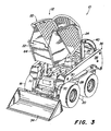
- Fig. 4
- das erfindungsgemäße Fahrzeug aus Figur 3 in einer Seitenansicht von links,
- Fig. 5
- ein Steuergestänge des erfindungsgemäßen Fahrzeugs in einer Betriebsstellung und in perspektivischer Darstellung und
- Fig. 6
- das Steuergestänge aus Figur 5 in einer Außerbetriebsstellung und in perspektivischer Darstellung.
Claims (9)
- Fahrzeug (10) mit einem Fahrzeugrahmen (28), einer Fahrerzelle (22) und wenigstens einem Steuergestänge (46), wobei die Fahrerzelle (22) in eine Betriebsstellung und in eine Außerbetriebsstellung bringbar ist und wobei in der Außerbetriebsstellung Zugang zu wenigstens einem Fahrzeugraum (30) unterhalb der Fahrerzelle (22) ermöglicht wird, dadurch gekennzeichnet, daß das Steuergestänge (46) eine Betriebsstellung, in der es wenigstens teilweise in die Fahrerzelle (22) ragt, und eine Außerbetriebsstellung einnehmen kann, in der es sich außerhalb des Bewegungsbereiches der Fahrerzelle (22) befindet.
- Fahrzeug nach Anspruch 1, dadurch gekennzeichnet, daß das Steuergestänge (46) beweglich ausgebildet ist und an der Fahrerzelle (22) angreift oder anliegt und infolge einer Bewegung der Fahrerzelle (22) mit dieser aus der Außerbetriebsstellung in die Betriebsstellung und umgekehrt gelangt.
- Fahrzeug nach Anspruch 1 oder 2, dadurch gekennzeichnet, daß das Steuergestänge (46) einen Betätigungshebel (16) aufweist, der eine im wesentlichen aufrechte Betriebsstellung und eine Außerbetriebsstellung einnehmen kann, in die er infolge einer abwärts gerichteten Bewegung gelangt.
- Fahrzeug nach einem oder mehreren der vorherigen Ansprüche, dadurch gekennzeichnet, daß die Fahrerzelle (22) eine abwärts gerichtete Bewegung des Betätigungshebels (16) freigibt, wenn sie aus der unteren Betriebsstellung in die darüberliegende Außerbetriebsstellung gelangt.
- Fahrzeug nach einem oder mehreren der vorherigen Ansprüche, dadurch gekennzeichnet, daß der Betätigungshebel (16) an einem Hebel (56) um eine erste Schwenkachse (58) und der Hebel (56) um eine zweite Schwenkachse (62) an dem Fahrzeugrahmen (28) schwenkbar angebracht ist, wobei beide Schwenkachsen (58, 62) zueinander radial versetzt sind und wobei ein Bewegungsübertragungslenker (52) zum Betätigen des Fahrzeugs (10) nahe der zweiten Schwenkachse (62) oder zu dieser fluchtend an dem Hebel (56) angebracht ist.
- Fahrzeug nach einem oder mehreren der vorherigen Ansprüche, dadurch gekennzeichnet, daß der Hebel (56) von der Fahrerzelle (22) um die zweite Schwenkachse (62) nach unten gedrückt und der Betätigungshebel (16) in die Betriebsstellung geschwenkt wird, wenn die Fahrerzelle (22) in der Betriebsstellung auf dem Hebel (56) aufsitzt.
- Fahrzeug nach einem oder mehreren der vorherigen Ansprüche, dadurch gekennzeichnet, daß der Schwerpunkt des Betätigungshebels (16) auf der mit Bezug auf die zweite Schwenkachse (62) dem Angriffspunkt der Fahrerzelle (22) gegenüberliegenden Seite des Hebels (56) angeordnet ist.
- Fahrzeug nach einem oder mehreren der vorherigen Ansprüche, dadurch gekennzeichnet, daß es als Rutsch-Lenk-Lader ausgebildet ist und der Betätigungshebel (16) zur Steuerung des Fahrantriebs dient.
- Fahrzeug nach einem oder mehreren der vorherigen Ansprüche, dadurch gekennzeichnet, daß der Hebel (56) im Bereich seiner Anlage an der Fahrerzelle (22) mit einem Dämpfer (78) versehen ist.
Applications Claiming Priority (2)
| Application Number | Priority Date | Filing Date | Title |
|---|---|---|---|
| US953560 | 1997-10-17 | ||
| US08/953,560 US5918694A (en) | 1997-10-17 | 1997-10-17 | Pivotable control lever mechanism |
Publications (3)
| Publication Number | Publication Date |
|---|---|
| EP0909856A2 EP0909856A2 (de) | 1999-04-21 |
| EP0909856A3 EP0909856A3 (de) | 1999-11-17 |
| EP0909856B1 true EP0909856B1 (de) | 2003-08-06 |
Family
ID=25494186
Family Applications (1)
| Application Number | Title | Priority Date | Filing Date |
|---|---|---|---|
| EP98119186A Expired - Lifetime EP0909856B1 (de) | 1997-10-17 | 1998-10-12 | Fahrzeug |
Country Status (8)
| Country | Link |
|---|---|
| US (1) | US5918694A (de) |
| EP (1) | EP0909856B1 (de) |
| JP (1) | JP3184801B2 (de) |
| KR (1) | KR19990036659A (de) |
| AU (1) | AU732698B2 (de) |
| CA (1) | CA2241199C (de) |
| DE (1) | DE59809192D1 (de) |
| ES (1) | ES2200251T3 (de) |
Families Citing this family (28)
| Publication number | Priority date | Publication date | Assignee | Title |
|---|---|---|---|---|
| US6108907A (en) * | 1998-06-05 | 2000-08-29 | Caterpillar S.A.R.L. | Method of assembling a work machine |
| US6098739A (en) * | 1998-06-05 | 2000-08-08 | Caterpillar S.A.R.L. | Main frame assembly |
| USD437862S1 (en) | 1999-11-05 | 2001-02-20 | Deere & Company | Window section |
| US6616398B2 (en) | 2000-11-30 | 2003-09-09 | Caterpillar S.A.R.L. | Lift boom assembly |
| DE10113311B4 (de) * | 2001-03-20 | 2004-02-19 | O&K Orenstein & Koppel Ag | Arbeitsmaschine, insbesondere Bagger |
| US6581704B2 (en) | 2001-06-21 | 2003-06-24 | Deere & Company | Steering controls |
| US7036623B2 (en) * | 2002-03-15 | 2006-05-02 | Unverferth Manufacturing Company, Inc. | Control configuration for a utility vehicle having, e.g., an extendable utility boom |
| US7214026B2 (en) * | 2002-03-15 | 2007-05-08 | Unverferth Manufacturing Company, Inc. | Easy maintenance and/or service utility vehicle with extendable utility boom |
| US6854546B2 (en) * | 2002-09-03 | 2005-02-15 | Clark Equipment Company | Auxiliary cab lift spring |
| US7396070B2 (en) * | 2004-05-26 | 2008-07-08 | Clark Equipment Company | Relocatable position operator seat station for loader |
| ATE544914T1 (de) * | 2006-03-30 | 2012-02-15 | Charles Machine Works | Steuersystem mit mehreren funktionen für eine arbeitsmaschine |
| USD583835S1 (en) * | 2008-02-29 | 2008-12-30 | Komatsu Ltd. | Skid-steer loader |
| USD583834S1 (en) * | 2008-02-29 | 2008-12-30 | Komatsu Ltd. | Skid-steer loader |
| USD600721S1 (en) * | 2008-06-06 | 2009-09-22 | Kubota Corporation | Skid steer loader |
| JP5015080B2 (ja) * | 2008-07-01 | 2012-08-29 | 株式会社クボタ | トラックローダ |
| US7946370B2 (en) * | 2009-03-17 | 2011-05-24 | Clark Equipment Company | Operator compartment assembly |
| RU2467907C2 (ru) * | 2011-02-28 | 2012-11-27 | Открытое акционерное общество "Красноярский завод лесного машиностроения" (ОАО "Краслесмаш") | Механизм наклона кабины лесопромышленного трактора колесного типа |
| EP2934992B1 (de) | 2012-12-20 | 2016-12-14 | CNH Industrial America LLC | Kabinenfederungssystem für ein arbeitsfahrzeug mit in rundum verlaufenden anschlagpuffern |
| US9017005B2 (en) * | 2013-01-30 | 2015-04-28 | Deere & Company | Skid steer loader lift linkage assembly |
| CN108602537A (zh) * | 2016-02-05 | 2018-09-28 | 克拉克设备公司 | 机械控制连接装置 |
| US10000244B2 (en) * | 2016-02-17 | 2018-06-19 | Wacker Neuson Production Americas, L.L.C. | Tiltable cabin |
| US11878743B2 (en) * | 2020-08-20 | 2024-01-23 | Doosan Bobcat North America Inc. | Assist mechanism for moving cab on power machine |
| US12296694B2 (en) | 2021-03-10 | 2025-05-13 | Techtronic Cordless Gp | Lawnmowers |
| US12077940B2 (en) * | 2021-09-13 | 2024-09-03 | Caterpillar Sarl | Systems, assemblies, and methods for implementing key plate for locking cab to main body of work machine |
| US12275460B2 (en) * | 2021-09-13 | 2025-04-15 | Caterpillar Sarl | Systems, assemblies, and methods for locking cab to main body of work machine |
| JP7662552B2 (ja) * | 2022-02-08 | 2025-04-15 | 株式会社クボタ | 作業車両 |
| USD1014568S1 (en) | 2022-02-14 | 2024-02-13 | Techtronic Cordless Gp | Lawn mower |
| USD1015381S1 (en) | 2022-02-14 | 2024-02-20 | Techtronic Cordless Gp | Lawn mower |
Family Cites Families (8)
| Publication number | Priority date | Publication date | Assignee | Title |
|---|---|---|---|---|
| US3618692A (en) | 1969-11-04 | 1971-11-09 | Universal Oil Prod Co | Vehicle cab suspension |
| US4276953A (en) * | 1980-01-28 | 1981-07-07 | Paccar Inc. | Shift linkage for a tilt cab truck |
| SE466651B (sv) * | 1988-05-09 | 1992-03-16 | Volvo Ab | Vaexelmekanism i ett fordon med tippbar hytt |
| US5042602A (en) * | 1989-08-18 | 1991-08-27 | Toyo Umpanki Co., Ltd. | Loader |
| SE470401B (sv) * | 1992-07-07 | 1994-02-14 | Saab Scania Ab | Växlingsmekanism för en växellåda i ett motorfordon |
| KR970005732Y1 (ko) * | 1993-12-30 | 1997-06-11 | 대우중공업 주식회사 | 스키드로다 캐노피(canopy)의 가스스프링 장착구조 |
| US5518358A (en) * | 1994-08-24 | 1996-05-21 | New Holland North America, Inc. | Skid steer loader with tiltable cab |
| US5553992A (en) * | 1994-10-24 | 1996-09-10 | New Holland North America, Inc. | Controls for a skid steer loader |
-
1997
- 1997-10-17 US US08/953,560 patent/US5918694A/en not_active Expired - Fee Related
-
1998
- 1998-07-20 CA CA002241199A patent/CA2241199C/en not_active Expired - Fee Related
- 1998-09-22 KR KR1019980039150A patent/KR19990036659A/ko not_active Ceased
- 1998-10-12 JP JP28896598A patent/JP3184801B2/ja not_active Expired - Fee Related
- 1998-10-12 EP EP98119186A patent/EP0909856B1/de not_active Expired - Lifetime
- 1998-10-12 DE DE59809192T patent/DE59809192D1/de not_active Expired - Fee Related
- 1998-10-12 ES ES98119186T patent/ES2200251T3/es not_active Expired - Lifetime
- 1998-10-13 AU AU89285/98A patent/AU732698B2/en not_active Ceased
Also Published As
| Publication number | Publication date |
|---|---|
| KR19990036659A (ko) | 1999-05-25 |
| AU8928598A (en) | 1999-05-06 |
| CA2241199A1 (en) | 1999-04-17 |
| ES2200251T3 (es) | 2004-03-01 |
| EP0909856A3 (de) | 1999-11-17 |
| EP0909856A2 (de) | 1999-04-21 |
| US5918694A (en) | 1999-07-06 |
| CA2241199C (en) | 2002-02-26 |
| JPH11217053A (ja) | 1999-08-10 |
| AU732698B2 (en) | 2001-04-26 |
| JP3184801B2 (ja) | 2001-07-09 |
| DE59809192D1 (de) | 2003-09-11 |
Similar Documents
| Publication | Publication Date | Title |
|---|---|---|
| EP0909856B1 (de) | Fahrzeug | |
| EP0131245B1 (de) | Schliess- und Feststellvorrichtung für einen an einem Schlepper schwenkbar gelagerten Sammelbehälter | |
| EP0909854B1 (de) | Laderfahrzeug | |
| EP1514463B1 (de) | Vorrichtung zur Kopplung eines Arbeitsgeräts an ein Arbeitsfahrzeug | |
| DE19951840A1 (de) | Anbauschnittstelle zur Kopplung von Arbeitsgeräten an ein Arbeitsfahrzeug | |
| EP1197368A2 (de) | Mehrteilige Abdeckung für Fahrzeuge | |
| DE2904151A1 (de) | Schwimmfaehiger personenkraftwagen als reise- und wassersport-mobil | |
| DE2854217A1 (de) | Sitz, insbesondere kraftfahrzeugsitz | |
| EP1008507A2 (de) | Lenkeinrichtung und Fahrzeug | |
| EP0230258A2 (de) | Vertikal verstellbare Steuersäule | |
| EP2832583B1 (de) | Landwirtschaftliches Fahrzeug | |
| DE19534695C2 (de) | An einem Schlepper ansetzbares Heckmähwerk | |
| DE2500857A1 (de) | Nutzfahrzeug mit mindestens einer hebevorrichtung | |
| DE19616070C2 (de) | Kraftfahrzeugsitz | |
| DE4117272A1 (de) | Geraetehaltevorrichtung zur verbindung eines arbeitsgeraetes mit einem fahrzeug | |
| EP1108582A2 (de) | Vorrichtung zur Verriegelung zweier relativ zueinander verstellbarer, zwangsgeführter Elemente | |
| DE69635839T2 (de) | Ansteuervorrichtung für arbeitsfahrzeug | |
| DE1455289C3 (de) | Kupplungsvorrichtung zum Verbinden eines für schienengebundenen Betrieb einrichtbaren, zum Rangieren dienenden Antriebsfahrzeugs mit einem Eisenbahnwagen | |
| DE3200157C2 (de) | ||
| EP0251174B1 (de) | Aufhängung eines Schwenkteils | |
| EP1674619B1 (de) | Umschlaggerät | |
| DE2705979A1 (de) | Vorrichtung an einem langen schleppoder anhaengerwagen | |
| EP0439068B1 (de) | Landwirtschaftliche Arbeitsmaschine | |
| EP0133637B1 (de) | Frontseitige Geräteanbauvorrichtung für ein frontverkleidetes land- und/oder bauwirtschaftlich nutzbares Kraftfahrzeug, insbesondere Ackerschlepper | |
| DE202011101157U1 (de) | Landwirtschaftliche Maschine |
Legal Events
| Date | Code | Title | Description |
|---|---|---|---|
| PUAI | Public reference made under article 153(3) epc to a published international application that has entered the european phase |
Free format text: ORIGINAL CODE: 0009012 |
|
| AK | Designated contracting states |
Kind code of ref document: A2 Designated state(s): DE ES FR GB IT |
|
| AX | Request for extension of the european patent |
Free format text: AL;LT;LV;MK;RO;SI |
|
| PUAL | Search report despatched |
Free format text: ORIGINAL CODE: 0009013 |
|
| AK | Designated contracting states |
Kind code of ref document: A3 Designated state(s): AT BE CH CY DE DK ES FI FR GB GR IE IT LI LU MC NL PT SE |
|
| AX | Request for extension of the european patent |
Free format text: AL;LT;LV;MK;RO;SI |
|
| RIC1 | Information provided on ipc code assigned before grant |
Free format text: 6E 02F 9/20 A, 6E 02F 9/16 B, 6B 62D 33/067 B |
|
| 17P | Request for examination filed |
Effective date: 20000330 |
|
| AKX | Designation fees paid |
Free format text: DE ES FR GB IT |
|
| GRAH | Despatch of communication of intention to grant a patent |
Free format text: ORIGINAL CODE: EPIDOS IGRA |
|
| GRAH | Despatch of communication of intention to grant a patent |
Free format text: ORIGINAL CODE: EPIDOS IGRA |
|
| GRAA | (expected) grant |
Free format text: ORIGINAL CODE: 0009210 |
|
| AK | Designated contracting states |
Designated state(s): DE ES FR GB IT |
|
| REG | Reference to a national code |
Ref country code: GB Ref legal event code: FG4D Free format text: NOT ENGLISH |
|
| REF | Corresponds to: |
Ref document number: 59809192 Country of ref document: DE Date of ref document: 20030911 Kind code of ref document: P |
|
| GBT | Gb: translation of ep patent filed (gb section 77(6)(a)/1977) |
Effective date: 20031008 |
|
| REG | Reference to a national code |
Ref country code: ES Ref legal event code: FG2A Ref document number: 2200251 Country of ref document: ES Kind code of ref document: T3 |
|
| ET | Fr: translation filed | ||
| PLBE | No opposition filed within time limit |
Free format text: ORIGINAL CODE: 0009261 |
|
| STAA | Information on the status of an ep patent application or granted ep patent |
Free format text: STATUS: NO OPPOSITION FILED WITHIN TIME LIMIT |
|
| 26N | No opposition filed |
Effective date: 20040507 |
|
| PGFP | Annual fee paid to national office [announced via postgrant information from national office to epo] |
Ref country code: DE Payment date: 20080919 Year of fee payment: 11 |
|
| PGFP | Annual fee paid to national office [announced via postgrant information from national office to epo] |
Ref country code: FR Payment date: 20081018 Year of fee payment: 11 |
|
| PGFP | Annual fee paid to national office [announced via postgrant information from national office to epo] |
Ref country code: GB Payment date: 20081029 Year of fee payment: 11 |
|
| REG | Reference to a national code |
Ref country code: FR Ref legal event code: ST Effective date: 20100630 |
|
| PG25 | Lapsed in a contracting state [announced via postgrant information from national office to epo] |
Ref country code: FR Free format text: LAPSE BECAUSE OF NON-PAYMENT OF DUE FEES Effective date: 20091102 Ref country code: DE Free format text: LAPSE BECAUSE OF NON-PAYMENT OF DUE FEES Effective date: 20100501 |
|
| PG25 | Lapsed in a contracting state [announced via postgrant information from national office to epo] |
Ref country code: GB Free format text: LAPSE BECAUSE OF NON-PAYMENT OF DUE FEES Effective date: 20091012 |
|
| PGFP | Annual fee paid to national office [announced via postgrant information from national office to epo] |
Ref country code: ES Payment date: 20131028 Year of fee payment: 16 Ref country code: IT Payment date: 20131025 Year of fee payment: 16 |
|
| PG25 | Lapsed in a contracting state [announced via postgrant information from national office to epo] |
Ref country code: IT Free format text: LAPSE BECAUSE OF NON-PAYMENT OF DUE FEES Effective date: 20141012 |
|
| REG | Reference to a national code |
Ref country code: ES Ref legal event code: FD2A Effective date: 20151127 |
|
| PG25 | Lapsed in a contracting state [announced via postgrant information from national office to epo] |
Ref country code: ES Free format text: LAPSE BECAUSE OF NON-PAYMENT OF DUE FEES Effective date: 20141013 |