EP0910108B1 - Lentille pour faisceau d'électrons - Google Patents
Lentille pour faisceau d'électrons Download PDFInfo
- Publication number
- EP0910108B1 EP0910108B1 EP97116909A EP97116909A EP0910108B1 EP 0910108 B1 EP0910108 B1 EP 0910108B1 EP 97116909 A EP97116909 A EP 97116909A EP 97116909 A EP97116909 A EP 97116909A EP 0910108 B1 EP0910108 B1 EP 0910108B1
- Authority
- EP
- European Patent Office
- Prior art keywords
- lens
- electron beam
- pole piece
- pole
- lens according
- Prior art date
- Legal status (The legal status is an assumption and is not a legal conclusion. Google has not performed a legal analysis and makes no representation as to the accuracy of the status listed.)
- Expired - Lifetime
Links
- 238000010894 electron beam technology Methods 0.000 title claims description 59
- 238000000605 extraction Methods 0.000 claims description 2
- 230000000979 retarding effect Effects 0.000 claims 1
- 239000011163 secondary particle Substances 0.000 claims 1
- 241000219739 Lens Species 0.000 description 73
- 230000003287 optical effect Effects 0.000 description 10
- 239000000523 sample Substances 0.000 description 9
- 230000000694 effects Effects 0.000 description 3
- 240000004322 Lens culinaris Species 0.000 description 2
- 230000015572 biosynthetic process Effects 0.000 description 2
- 230000005405 multipole Effects 0.000 description 2
- 230000005684 electric field Effects 0.000 description 1
- 230000003116 impacting effect Effects 0.000 description 1
Images


Classifications
-
- H—ELECTRICITY
- H01—ELECTRIC ELEMENTS
- H01J—ELECTRIC DISCHARGE TUBES OR DISCHARGE LAMPS
- H01J37/00—Discharge tubes with provision for introducing objects or material to be exposed to the discharge, e.g. for the purpose of examination or processing thereof
- H01J37/02—Details
- H01J37/04—Arrangements of electrodes and associated parts for generating or controlling the discharge, e.g. electron-optical arrangement or ion-optical arrangement
- H01J37/10—Lenses
- H01J37/145—Combinations of electrostatic and magnetic lenses
-
- H—ELECTRICITY
- H01—ELECTRIC ELEMENTS
- H01J—ELECTRIC DISCHARGE TUBES OR DISCHARGE LAMPS
- H01J37/00—Discharge tubes with provision for introducing objects or material to be exposed to the discharge, e.g. for the purpose of examination or processing thereof
- H01J37/02—Details
- H01J37/04—Arrangements of electrodes and associated parts for generating or controlling the discharge, e.g. electron-optical arrangement or ion-optical arrangement
- H01J37/10—Lenses
- H01J37/14—Lenses magnetic
- H01J37/141—Electromagnetic lenses
Definitions
- the invention relates to an electron beam lens, containing a magnetic lens to influence a Electron beam with a first and a second Pole shoe, with a magnetic field between the two Forms pole pieces and also a third pole piece is provided.
- the invention further relates to a cathode lens and an electron beam device with such an electron beam lens.
- a magnetic lens Influencing an electron beam known to be an upper one and has a lower pole piece and a third pole piece which is placed between the other two pole pieces and is not in magnetic contact with them.
- a multipole lens is known from EP-A-0 133 016, which essentially consists of a series of there are two bipolar lenses of the type described above.
- the electron beam lens according to the preamble of claim 1 in their optical properties for the primary beam and in their Collection properties for the secondary rays further to improve.
- the electron beam lens is characterized in that the third pole piece in the between the first and second pole shoe trained magnetic field immersed and thereby decouples part of this magnetic field, being the decoupled part of the main magnetic field at the bottom Forms a secondary field at the end of the third pole piece.
- the decoupled part of the (main) magnetic field forms a second lens field at the lower end of the third pole piece (Secondary field).
- the secondary field has on the one hand a focusing effect on the primary beam and good optical properties due to its proximity to the sample and on the other hand prevents the secondary rays from moving expand.
- the secondary beam can therefore enter the lens system "bundled" and from one Spectrometer / detector arrangement or a detector in or above the lens with high efficiency be detected.
- the Electron beam lens advantageous in a cathode lens used By that generated by the third pole piece Secondary field ensures that this is positive bring the impacting magnetic field close to the cathode leaves without the need for a large physical lens is. Thanks to the suitable design of the three-pole magnetic lens can the strength of the secondary field on the Cathode tip and the optical properties of the as Condenser acting first and second pole pieces separately optimize.
- the electron beam lens in an electron beam device used.
- the Samples are tilted with respect to the primary beam.
- the special design of the electron beam lens enables if the working distance is short, a strong tilting or offers space for other optional elements such as detectors, Manipulators etc.
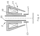
- the electron beam lens shown in Fig.1a has a magnetic lens 1 for influencing an electron beam with a first, inner pole piece 10 and a second, outer pole piece 11.
- the first and second Pole shoe 10, 11 are in the illustrated embodiment as a two-pole lens with a conical outer Pole shoe 11 and a coil 15 shown, wherein there is a magnetic between the first and second pole pieces Main field 12 trains.
- the magnetic lens 1 also has a third pole piece 13 that is not in magnetic contact with the The other two pole pieces stand between the two first and second pole shoe 10, 11 formed magnetic field dips.
- the third pole piece 13 is preferred cylindrical and dips into the main field 12 that part of this magnetic field is coupled out becomes.
- 1b shows the spread of the main field 12 and of the secondary field 14 shown.
- the strenght the secondary field 14 depends on how far the third Pole shoe 13 dips into the main field and a corresponding one Share of the magnetic field and how large the gap to the inner or outer pole piece 10, 11th is.
- the third pole piece 13 expediently in relation to the first and second pole pieces 10, 11 slidably or arranged adjustable.
- the maxima of the axial magnetic fields of the main and secondary fields are designated B 1 and B 2 .
- the third pole piece is preferably arranged in relation to the first and second pole pieces such that the amplitude B 2 of the secondary field is at least 15%, preferably between 20% and 60% of the amplitude B 1 of the main field.
- Magnetic three-pole lens shows a conventional Fig. 2a Two-pole lens with a first and second pole 10, 11. Accordingly, only a magnetic field is formed 12, whose distribution is shown in Fig.2b is.
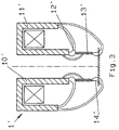
- FIG. 3 shows a second exemplary embodiment according to the invention an electron beam lens that differs from the 1a differs only in that that by a first pole piece 10 ' and formed by a second pole piece 11 ' Magnet lens 1 'is designed as a single-pole lens.
- a main and a secondary field are formed 12 ', 14'.
- the advantage of using a single pole lens in combination with a third pole piece 13 ' is mainly that with the single pole lens generates a particularly strong magnetic field and accordingly also a strong part passed on as secondary field 14 ' can be.
- the two electron beam lenses shown in Figures 1a and 3 can also be advantageous with a electrostatic lens, especially an electrostatic Combine brake lens.
- the electrostatic Lens consists of at least a first and a second, with different potentials Electrode.
- 1a is an example of an electrostatic Shown lens 2
- the first electrode consists of a jet pipe 20 which is coaxial to first pole piece 10 arranged inside the magnetic lens 1 is.
- the second electrode is replaced by the third Pole shoe 13 formed.
- the jet pipe 20 for example has high positive potential a suitable, lower one on the third pole piece 13 Apply positive or negative voltage U to the desired braking effect on the electron beam produce.
- the jet pipe 20 is wider pulled down so that it is in the third pole piece 13 dips.
- the electrostatic lens forms in this case in the area of the submerged end of the first Electrode 20 and the adjacent wall of the third pole piece 13.
- the second Electrode of the electrostatic lens 2 not through the third pole piece 13, but by a separate, in the pole shoe 13 inserted tube electrode 21 is formed.
- this tube electrode 21 transversely to the optical axis 16 or is interrupted several times in order to electrostatic lens through at least three electrodes build.
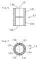
- Fig. 6 shows an alternative way of building the electrostatic lens made up of more than two electrodes.
- the third pole piece 13 part of the electrostatic Lens the pole piece transverse to the optical axis 16 divided into a first part 13c and a second part 13d is.
- These two parts 13c, 13d form the second and third electrodes of the electrostatic lens and can have different potentials for this purpose be charged.
- the gap between the two parts 13c, 13d of the third pole piece 13 is as small as possible, the "absorbed" magnetic field is unhindered by the upper one End 13a led to the lower end 13b.
- FIG. 1 An exemplary embodiment is shown in FIG which is the second electrode of the electrostatic lens is in turn formed by the third pole piece.
- This third pole piece is however in the direction of the optical Axis 16 slotted, so that in illustrated embodiment eight segments 13e, 13f, 13g, 13h, 13i, 13k, 13l, 13m.
- This Segments represent electrical multipole elements that by suitably applying voltages as electrostatic deflector, stigmator or the like can be switched and used.
- the single ones Tensions are chosen so that there is a average voltage gives that of the voltage U the corresponds to the second electrode. But it is also a fewer or larger number of segments possible.
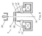
- Fig. 8 shows an application example of the shown electron beam lenses in a cathode lens 3.
- the cathode lens 3 essentially consists of a cathode 30 with "suppressor" electrode, an extraction electrode 31, an anode 32 and an electron beam lens according to one of the two in FIGS. 1a, 3 to 7 embodiments shown.
- the Electron beam lens 1 was the Electron beam lens 1 'selected according to Figure 3.
- the Electron beam lens is installed so that the secondary field 14 'forming as close as possible to the cathode 30 can be brought up and through the two pole pieces 10 ', 11' formed single-pole lens as a condenser acts.
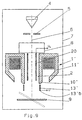
- FIG. 9 shows an application of the electron beam lens represented in an electron beam device.
- the electron beam device is made by an optical column 7 is formed, which essentially a source 4 for generating an electron beam 6, a magnetic lens 1 'and a spectrometer / detector arrangement 8 has.
- a blanking system 5 and a tiltable sample table 9 is shown.
- the electron beam lens used here corresponds to the exemplary embodiment shown in FIG. 3, in which the two first pole pieces 10 ', 11' form a single pole lens which is combined with a third pole piece 13 '.
- the electrostatic lens 2 is in turn formed by a beam tube 20 inserted into the single-pole lens as the first electrode and by the lower part of the third pole piece 13 'as the second electrode.
- the beam tube 20 and the part of the third pole piece 13 ′ serving as the second electrode can be acted upon with different potentials U L and U, respectively.
- the spectrometer / detector arrangement 8 or a detector is in the direction of the electron beam 6 arranged in front of or above the magnetic lens 1 '. It however, it would also be conceivable to place the detector within the Magnetic lens 1 'to be provided.
- the detectors can either one-sided, rotationally symmetrical or in segmented form or as a combined Backscatter / secondary electron detectors are formed his. But also an arrangement of the detector between Magnet lens and sample would be conceivable.
- the formation of the magnetic lens 1 'as a three-pole lens with the three pole pieces 10', 11 ', 13' has the further advantage that the lower end of this three-pole lens is smaller or more pointed than in conventional two-pole lenses.
- This design is particularly advantageous in the case of tiltable sample tables, since it enables a larger tilt angle ⁇ to be achieved.
- FIGS. 1a and 2a which each show the maximum tilt angle ⁇ 1 and ⁇ 2 .
- the maximum tilt angle ⁇ 1 is greater than the angle ⁇ 2 in the prior art. This property is particularly helpful when examining samples with a very short working distance, since a large tilt angle is still available.
- the additional space available can also for optional elements such as detectors, manipulators etc. can be exploited.
Landscapes
- Chemical & Material Sciences (AREA)
- Analytical Chemistry (AREA)
- Physics & Mathematics (AREA)
- Electromagnetism (AREA)
- Electron Beam Exposure (AREA)
- Electron Tubes For Measurement (AREA)
Claims (16)
- Lentille pour faisceau d'électrons, qui contient une lentille magnétique (1, 1') qui agit sur un faisceau d'électrons (6), avec une première et une deuxième pièces polaires (10, 11, 10', 11') entre lesquelles est formé un champ magnétique principal (12), une troisième pièce polaire (13, 13') qui n'est pas en contact magnétique avec les deux autres pièces polaires étant en outre prévue,
caractérisée en ce que la troisième pièce polaire se trouve dans le champ magnétique principal (12) situé entre la première et la deuxième pièces polaires et découple une partie de ce champ magnétique, la partie découplée du champ magnétique principal formant un champ secondaire à l'extrémité inférieure de la troisième pièce polaire. - Lentille pour faisceau d'électrons selon la revendication 1, caractérisée en ce que la troisième pièce polaire (13, 13') a une forme cylindrique.
- Lentille pour faisceau d'électrons selon la revendication 1, caractérisée en ce que la troisième pièce polaire (13, 13') est agencée de manière à pouvoir être déplacée par rapport à la première et à la deuxième pièces polaires (10, 11, 10', 11').
- Lentille pour faisceau d'électrons selon la revendication 1, caractérisée en ce que la première et la deuxième pièces polaires (10, 11) sont configurées comme lentille bipolaire.
- Lentille pour faisceau d'électrons selon la revendication 1, caractérisée en ce que la lentille bipolaire est conique.
- Lentille pour faisceau d'électrons selon la revendication 4, caractérisée en ce que la première et la deuxième pièces polaires (10', 11') sont configurées comme lentille unipolaire.
- Lentille pour faisceau d'électrons selon la revendication 1, caractérisée en ce qu'une lentille électrostatique (2) est prévue à l'intérieur de la lentille magnétique (1, 1').
- Lentille pour faisceau d'électrons selon la revendication 7, caractérisée en ce que la lentille électrostatique (2) est configurée comme lentille de freinage.
- Lentille pour faisceau d'électrons selon la revendication 7, caractérisée en ce que la lentille électrostatique (2) présente au moins une première et une deuxième électrodes sur lesquelles on peut appliquer des potentiels différents.
- Lentille pour faisceau d'électrons selon la revendication 7, caractérisée en ce que la lentille électrostatique (2) présente au moins deux électrodes dont l'une est formée par la troisième pièce polaire (13, 13').
- Lentille pour faisceau d'électrons selon la revendication 10, caractérisée en ce que la troisième pièce polaire est divisée en segments sur lesquels ont peut appliquer des potentiels différents.
- Lentille pour faisceau d'électrons selon la revendication 7, caractérisée en ce que la lentille électrostatique (2) présente au moins deux électrodes, l'une de ces électrodes étant introduite comme tube à faisceau (20) à travers une partie de la lentille magnétique (1, 1') formée par la première et la deuxième pièces polaires (10, 11, 10', 11').
- Lentille de cathode, qui présente
une cathode (30),
une électrode d'extraction (31),
une anode (32)
et une lentille pour faisceau d'électrons selon l'une des revendications 1 à 11. - Dispositif à faisceau d'électrons qui présente une source (4) pour la production d'un faisceau d'électrons (6),
une lentille pour faisceau d'électrons, pour concentrer le faisceau d'électrons sur un échantillon, selon l'une des revendications 1 à 11. - Dispositif à faisceau d'électrons selon la revendication 14, caractérisé en ce que qu'un porte-échantillon basculant (9) est prévu.
- Dispositif à faisceau d'électrons selon la revendication 14, caractérisé en ce qu'un agencement composé d'un détecteur et d'un spectromètre est prévu pour détecter les particules secondaires qui se dégagent de l'échantillon.
Priority Applications (4)
| Application Number | Priority Date | Filing Date | Title |
|---|---|---|---|
| DE59712097T DE59712097D1 (de) | 1997-09-29 | 1997-09-29 | Elektronenstrahl-Linse |
| EP97116909A EP0910108B1 (fr) | 1997-09-29 | 1997-09-29 | Lentille pour faisceau d'électrons |
| US09/113,048 US6107633A (en) | 1997-09-29 | 1998-07-09 | Electron beam lens |
| JP10233055A JPH11120950A (ja) | 1997-09-29 | 1998-08-19 | 電子線レンズ装置 |
Applications Claiming Priority (1)
| Application Number | Priority Date | Filing Date | Title |
|---|---|---|---|
| EP97116909A EP0910108B1 (fr) | 1997-09-29 | 1997-09-29 | Lentille pour faisceau d'électrons |
Publications (2)
| Publication Number | Publication Date |
|---|---|
| EP0910108A1 EP0910108A1 (fr) | 1999-04-21 |
| EP0910108B1 true EP0910108B1 (fr) | 2004-11-24 |
Family
ID=8227414
Family Applications (1)
| Application Number | Title | Priority Date | Filing Date |
|---|---|---|---|
| EP97116909A Expired - Lifetime EP0910108B1 (fr) | 1997-09-29 | 1997-09-29 | Lentille pour faisceau d'électrons |
Country Status (4)
| Country | Link |
|---|---|
| US (1) | US6107633A (fr) |
| EP (1) | EP0910108B1 (fr) |
| JP (1) | JPH11120950A (fr) |
| DE (1) | DE59712097D1 (fr) |
Families Citing this family (15)
| Publication number | Priority date | Publication date | Assignee | Title |
|---|---|---|---|---|
| US6787772B2 (en) * | 2000-01-25 | 2004-09-07 | Hitachi, Ltd. | Scanning electron microscope |
| US6891167B2 (en) * | 2000-06-15 | 2005-05-10 | Kla-Tencor Technologies | Apparatus and method for applying feedback control to a magnetic lens |
| WO2001097245A2 (fr) * | 2000-06-15 | 2001-12-20 | Kla-Tencor, Inc. | Lentille magnetique a secteurs et procede d'utilisation |
| JP2002134051A (ja) * | 2000-10-20 | 2002-05-10 | Seiko Instruments Inc | 電磁界重畳型レンズ及びこれを用いた電子線装置 |
| DE10233002B4 (de) * | 2002-07-19 | 2006-05-04 | Leo Elektronenmikroskopie Gmbh | Objektivlinse für ein Elektronenmikroskopiesystem und Elektronenmikroskopiesystem |
| DE10317894B9 (de) | 2003-04-17 | 2007-03-22 | Leo Elektronenmikroskopie Gmbh | Fokussiersystem für geladene Teilchen, Elektronenmikroskopiesystem und Elektronenmikroskopieverfahren |
| JP4588602B2 (ja) * | 2005-09-30 | 2010-12-01 | 株式会社トプコン | 静電偏向器の製造方法 |
| EP2267753A3 (fr) * | 2005-11-28 | 2011-01-26 | Carl Zeiss SMT AG | Composant optique corpusculaire |
| DE102007010873B4 (de) * | 2007-03-06 | 2009-07-30 | Carl Zeiss Nts Gmbh | Objektivlinse |
| US8294095B2 (en) * | 2010-12-14 | 2012-10-23 | Hermes Microvision, Inc. | Apparatus of plural charged particle beams with multi-axis magnetic lens |
| JP6258474B2 (ja) * | 2014-04-28 | 2018-01-10 | 株式会社日立ハイテクノロジーズ | 電子線装置 |
| US10777382B2 (en) * | 2017-11-21 | 2020-09-15 | Focus-Ebeam Technology (Beijing) Co., Ltd. | Low voltage scanning electron microscope and method for specimen observation |
| CN114256043B (zh) | 2020-12-02 | 2024-04-05 | 聚束科技(北京)有限公司 | 一种电子束系统 |
| CN114220725B (zh) | 2020-12-02 | 2024-05-07 | 聚束科技(北京)有限公司 | 一种电子显微镜 |
| DE102023112074B4 (de) * | 2023-05-09 | 2024-11-28 | Carl Zeiss Microscopy Gmbh | Verfahren zum Betreiben eines Elektronenstrahlsystems und Computerprogrammprodukt |
Family Cites Families (9)
| Publication number | Priority date | Publication date | Assignee | Title |
|---|---|---|---|---|
| JPS5842935B2 (ja) * | 1978-04-07 | 1983-09-22 | 日本電子株式会社 | 走査電子顕微鏡等の対物レンズ |
| JPS57118357A (en) * | 1981-01-14 | 1982-07-23 | Jeol Ltd | Objective lens for scan type electron microscope |
| US4544847A (en) * | 1983-07-28 | 1985-10-01 | Varian Associates, Inc. | Multi-gap magnetic imaging lens for charged particle beams |
| FR2644930B1 (fr) * | 1989-03-21 | 1996-04-26 | Cameca | Lentille electromagnetique composite a focale variable |
| US5644132A (en) * | 1994-06-20 | 1997-07-01 | Opan Technologies Ltd. | System for high resolution imaging and measurement of topographic and material features on a specimen |
| TW306009B (fr) * | 1995-09-05 | 1997-05-21 | Matsushita Electron Co Ltd | |
| US5780859A (en) * | 1996-02-16 | 1998-07-14 | Act Advanced Circuit Testing Gesellschaft | Electrostatic-magnetic lens arrangement |
| EP0821393B1 (fr) * | 1996-07-25 | 1999-06-16 | ACT Advanced Circuit Testing Gesellschaft für Testsystementwicklung mbH | Lentille objectif de détecteur |
| JPH10255705A (ja) * | 1997-03-13 | 1998-09-25 | Nikon Corp | 2重対称磁気レンズおよび2段磁気レンズ系 |
-
1997
- 1997-09-29 EP EP97116909A patent/EP0910108B1/fr not_active Expired - Lifetime
- 1997-09-29 DE DE59712097T patent/DE59712097D1/de not_active Expired - Fee Related
-
1998
- 1998-07-09 US US09/113,048 patent/US6107633A/en not_active Expired - Fee Related
- 1998-08-19 JP JP10233055A patent/JPH11120950A/ja active Pending
Also Published As
| Publication number | Publication date |
|---|---|
| JPH11120950A (ja) | 1999-04-30 |
| US6107633A (en) | 2000-08-22 |
| DE59712097D1 (de) | 2004-12-30 |
| EP0910108A1 (fr) | 1999-04-21 |
Similar Documents
| Publication | Publication Date | Title |
|---|---|---|
| EP0218920B1 (fr) | Filtre d'énergie électronique de type Oméga | |
| EP0910108B1 (fr) | Lentille pour faisceau d'électrons | |
| EP0893816B1 (fr) | Appareil à faisceau corpusculaire | |
| EP0242602B1 (fr) | Lentille électrostatique et magnétique pour appareils à faisceau corpusculaire | |
| EP1277221B1 (fr) | Canon electronique pour electrons ou faisceaux ioniques de haute monochromie ou de haute densite de courant | |
| DE2850411C2 (de) | Elektronenstrahlerzeugungssystem in einer Kathodenstrahlröhre | |
| EP0617451B1 (fr) | Filtre en énergie d'électrons, produisant une image | |
| DE10235456B4 (de) | Elektronenmikroskopiesystem | |
| DE69118492T2 (de) | Massenspektrometer mit elektrostatischem Energiefilter | |
| DE3913965A1 (de) | Direkt abbildendes sekundaerionen-massenspektrometer mit laufzeit-massenspektrometrischer betriebsart | |
| EP0461442A2 (fr) | Appareil à faisceau de particules | |
| DE69920182T2 (de) | Korpuskularstrahloptisches gerät mit auger-elektronendetektion | |
| DE2255302C3 (de) | Einrichtung für die Sekundär-Ionen-Massenspektroskopie | |
| DE69602936T2 (de) | Detektor-Objektivlinse | |
| EP0911860B1 (fr) | Appareil à faisceau de particules chargées avec filtre en énergie | |
| DE69633338T2 (de) | Elektrostatische Vorrichtung zur Einwirkung auf einen Korpuskularstrahl | |
| EP0910109B1 (fr) | Lentille objectif | |
| DE69817618T2 (de) | Wien filter | |
| DE102010001349B9 (de) | Vorrichtung zum Fokussieren sowie zum Speichern von Ionen | |
| DE4037029C2 (de) | Elektronenkanone für eine Farbkathodenstrahlröhre | |
| DE2608958A1 (de) | Vorrichtung zum erzeugen von strahlen aus geladenen teilchen | |
| DE69605053T2 (de) | Kanonenlinse zur Partikelstrahlerzeugung | |
| DE69633505T2 (de) | Ablenksystem | |
| DE2004256A1 (de) | Verfahren und Vorrichtung zur Oberflaechenanalyse mittels Elektronenstrahl | |
| DE69606515T2 (de) | Elektrostatisch-magnetische Linsenanordnung |
Legal Events
| Date | Code | Title | Description |
|---|---|---|---|
| PUAI | Public reference made under article 153(3) epc to a published international application that has entered the european phase |
Free format text: ORIGINAL CODE: 0009012 |
|
| 17P | Request for examination filed |
Effective date: 19980515 |
|
| AK | Designated contracting states |
Kind code of ref document: A1 Designated state(s): DE FR GB NL |
|
| AKX | Designation fees paid |
Free format text: DE FR GB NL |
|
| 17Q | First examination report despatched |
Effective date: 20000222 |
|
| GRAP | Despatch of communication of intention to grant a patent |
Free format text: ORIGINAL CODE: EPIDOSNIGR1 |
|
| GRAS | Grant fee paid |
Free format text: ORIGINAL CODE: EPIDOSNIGR3 |
|
| GRAA | (expected) grant |
Free format text: ORIGINAL CODE: 0009210 |
|
| AK | Designated contracting states |
Kind code of ref document: B1 Designated state(s): DE FR GB NL |
|
| REG | Reference to a national code |
Ref country code: GB Ref legal event code: FG4D Free format text: NOT ENGLISH |
|
| REF | Corresponds to: |
Ref document number: 59712097 Country of ref document: DE Date of ref document: 20041230 Kind code of ref document: P |
|
| GBT | Gb: translation of ep patent filed (gb section 77(6)(a)/1977) |
Effective date: 20050113 |
|
| ET | Fr: translation filed | ||
| PLBE | No opposition filed within time limit |
Free format text: ORIGINAL CODE: 0009261 |
|
| STAA | Information on the status of an ep patent application or granted ep patent |
Free format text: STATUS: NO OPPOSITION FILED WITHIN TIME LIMIT |
|
| 26N | No opposition filed |
Effective date: 20050825 |
|
| PGFP | Annual fee paid to national office [announced via postgrant information from national office to epo] |
Ref country code: NL Payment date: 20080821 Year of fee payment: 12 Ref country code: FR Payment date: 20080811 Year of fee payment: 12 |
|
| PGFP | Annual fee paid to national office [announced via postgrant information from national office to epo] |
Ref country code: GB Payment date: 20080822 Year of fee payment: 12 |
|
| PGFP | Annual fee paid to national office [announced via postgrant information from national office to epo] |
Ref country code: DE Payment date: 20081120 Year of fee payment: 12 |
|
| REG | Reference to a national code |
Ref country code: NL Ref legal event code: V1 Effective date: 20100401 |
|
| GBPC | Gb: european patent ceased through non-payment of renewal fee |
Effective date: 20090929 |
|
| REG | Reference to a national code |
Ref country code: FR Ref legal event code: ST Effective date: 20100531 |
|
| PG25 | Lapsed in a contracting state [announced via postgrant information from national office to epo] |
Ref country code: NL Free format text: LAPSE BECAUSE OF NON-PAYMENT OF DUE FEES Effective date: 20100401 Ref country code: FR Free format text: LAPSE BECAUSE OF NON-PAYMENT OF DUE FEES Effective date: 20090930 Ref country code: DE Free format text: LAPSE BECAUSE OF NON-PAYMENT OF DUE FEES Effective date: 20100401 |
|
| PG25 | Lapsed in a contracting state [announced via postgrant information from national office to epo] |
Ref country code: GB Free format text: LAPSE BECAUSE OF NON-PAYMENT OF DUE FEES Effective date: 20090929 |