EP0910284B1 - Zange für optische biopsie - Google Patents
Zange für optische biopsie Download PDFInfo
- Publication number
- EP0910284B1 EP0910284B1 EP97922685A EP97922685A EP0910284B1 EP 0910284 B1 EP0910284 B1 EP 0910284B1 EP 97922685 A EP97922685 A EP 97922685A EP 97922685 A EP97922685 A EP 97922685A EP 0910284 B1 EP0910284 B1 EP 0910284B1
- Authority
- EP
- European Patent Office
- Prior art keywords
- jaws
- optical
- tubular member
- optical fiber
- forceps
- Prior art date
- Legal status (The legal status is an assumption and is not a legal conclusion. Google has not performed a legal analysis and makes no representation as to the accuracy of the status listed.)
- Expired - Lifetime
Links
- 238000001574 biopsy Methods 0.000 title claims abstract description 71
- 230000003287 optical effect Effects 0.000 title claims abstract description 55
- 239000013307 optical fiber Substances 0.000 claims abstract description 77
- 238000004458 analytical method Methods 0.000 claims abstract description 18
- 230000007246 mechanism Effects 0.000 claims description 8
- 239000000835 fiber Substances 0.000 abstract description 18
- 238000000034 method Methods 0.000 abstract description 13
- 238000005070 sampling Methods 0.000 abstract description 5
- 238000010183 spectrum analysis Methods 0.000 abstract description 3
- 239000000523 sample Substances 0.000 description 17
- 239000004033 plastic Substances 0.000 description 16
- 230000001681 protective effect Effects 0.000 description 6
- 229910001220 stainless steel Inorganic materials 0.000 description 6
- 239000010935 stainless steel Substances 0.000 description 6
- 238000003745 diagnosis Methods 0.000 description 5
- 238000003384 imaging method Methods 0.000 description 5
- 239000000463 material Substances 0.000 description 5
- 230000003014 reinforcing effect Effects 0.000 description 5
- 230000002792 vascular Effects 0.000 description 5
- 238000012306 spectroscopic technique Methods 0.000 description 4
- 201000010099 disease Diseases 0.000 description 3
- 208000037265 diseases, disorders, signs and symptoms Diseases 0.000 description 3
- 238000005286 illumination Methods 0.000 description 3
- 238000001727 in vivo Methods 0.000 description 3
- 230000002787 reinforcement Effects 0.000 description 3
- 238000004611 spectroscopical analysis Methods 0.000 description 3
- 230000008901 benefit Effects 0.000 description 2
- 239000004568 cement Substances 0.000 description 2
- 239000000975 dye Substances 0.000 description 2
- 210000005069 ears Anatomy 0.000 description 2
- 239000002905 metal composite material Substances 0.000 description 2
- 230000001225 therapeutic effect Effects 0.000 description 2
- 206010000060 Abdominal distension Diseases 0.000 description 1
- 239000004593 Epoxy Substances 0.000 description 1
- 239000004677 Nylon Substances 0.000 description 1
- 239000004952 Polyamide Substances 0.000 description 1
- 239000000853 adhesive Substances 0.000 description 1
- 230000001070 adhesive effect Effects 0.000 description 1
- 238000002399 angioplasty Methods 0.000 description 1
- 230000003143 atherosclerotic effect Effects 0.000 description 1
- 230000002457 bidirectional effect Effects 0.000 description 1
- 210000000621 bronchi Anatomy 0.000 description 1
- 230000015271 coagulation Effects 0.000 description 1
- 238000005345 coagulation Methods 0.000 description 1
- 238000002788 crimping Methods 0.000 description 1
- 238000012377 drug delivery Methods 0.000 description 1
- 229920006334 epoxy coating Polymers 0.000 description 1
- 238000002682 general surgery Methods 0.000 description 1
- 230000006872 improvement Effects 0.000 description 1
- 238000011005 laboratory method Methods 0.000 description 1
- 238000000608 laser ablation Methods 0.000 description 1
- 230000003902 lesion Effects 0.000 description 1
- 210000003750 lower gastrointestinal tract Anatomy 0.000 description 1
- 238000005259 measurement Methods 0.000 description 1
- 239000002184 metal Substances 0.000 description 1
- 229920001778 nylon Polymers 0.000 description 1
- 229920002647 polyamide Polymers 0.000 description 1
- 230000008569 process Effects 0.000 description 1
- 238000001356 surgical procedure Methods 0.000 description 1
- 210000003437 trachea Anatomy 0.000 description 1
- 210000002438 upper gastrointestinal tract Anatomy 0.000 description 1
- 210000003708 urethra Anatomy 0.000 description 1
- 230000000007 visual effect Effects 0.000 description 1
Images




Classifications
-
- A—HUMAN NECESSITIES
- A61—MEDICAL OR VETERINARY SCIENCE; HYGIENE
- A61B—DIAGNOSIS; SURGERY; IDENTIFICATION
- A61B10/00—Instruments for taking body samples for diagnostic purposes; Other methods or instruments for diagnosis, e.g. for vaccination diagnosis, sex determination or ovulation-period determination; Throat striking implements
- A61B10/02—Instruments for taking cell samples or for biopsy
- A61B10/06—Biopsy forceps, e.g. with cup-shaped jaws
-
- A—HUMAN NECESSITIES
- A61—MEDICAL OR VETERINARY SCIENCE; HYGIENE
- A61B—DIAGNOSIS; SURGERY; IDENTIFICATION
- A61B90/00—Instruments, implements or accessories specially adapted for surgery or diagnosis and not covered by any of the groups A61B1/00 - A61B50/00, e.g. for luxation treatment or for protecting wound edges
- A61B90/30—Devices for illuminating a surgical field, the devices having an interrelation with other surgical devices or with a surgical procedure
- A61B2090/306—Devices for illuminating a surgical field, the devices having an interrelation with other surgical devices or with a surgical procedure using optical fibres
-
- A—HUMAN NECESSITIES
- A61—MEDICAL OR VETERINARY SCIENCE; HYGIENE
- A61B—DIAGNOSIS; SURGERY; IDENTIFICATION
- A61B90/00—Instruments, implements or accessories specially adapted for surgery or diagnosis and not covered by any of the groups A61B1/00 - A61B50/00, e.g. for luxation treatment or for protecting wound edges
- A61B90/36—Image-producing devices or illumination devices not otherwise provided for
- A61B90/361—Image-producing devices, e.g. surgical cameras
- A61B2090/3614—Image-producing devices, e.g. surgical cameras using optical fibre
Definitions
- This invention pertains to the field of medical diagnosis and treatment. More specifically, the invention pertains to a forceps device having integrated optical fiber and remotely controllable biopsy forceps functions, and to the use thereof in medical diagnosis.
- the catheter is adapted for in vivo tissue identification of tissue types through optical techniques using the optical fiber, and biopsy sampling of identified tissue areas for withdrawal from the body for conventional examination and analysis.
- biopsy forceps devices Numerous type of biopsy forceps devices have been developed for in vivo medical diagnosis and treatment of various conditions. Such devices are designed for sampling tissue within the body, for example in endoscopic, laparoscopic and vascular procedures to retrieve biopsy samples for analysis and identification of tissue types.
- An urethroscope is described in U.S. Patent No. 4,557,255 which relates to a rigid main portion dimensioned to be received in the urethra and is adapted for carrying out surgical procedures under direct visual control.
- U.S. Patent No. 4,557,255 which relates to a rigid main portion dimensioned to be received in the urethra and is adapted for carrying out surgical procedures under direct visual control.
- One significant drawback with these endoscopes is that they are rigid and cumbersome to advance to an area of interest. In addition, it is difficult to view the area of interest because of the internal location within the patient.
- Biopsy forceps devices which are used in conjunction with the endoscope, generally include small cutting jaws at the distal end, operated remotely from the proximal end after the distal end of the device has been positioned or navigated to the site of interest.
- the present invention provides an integrated fiber optic biopsy forceps device, which is very thin, enabling it to be used in very small areas of interest, and which has a coaxial alignment of the optic field of view and the biopsy zone of sampling.
- the present invention provides an optical biopsy forceps which is adapted for tissue identification both by optical techniques and biopsy sampling.
- the forceps device includes an elongated catheter body for introduction into the body and navigation to an area of interest.
- the distal end of the forceps device has a pair of cutting jaws, and the tip of an optical fiber which runs through the forceps device.
- the proximal end has a control handle for manipulating the forceps device and actuating the jaws.
- the cutting jaws are mounted for pivoting or other movement bringing them together for cutting tissue placed therebetween, and coupled to and controlled by the optical fiber that extends through the catheter body to the handle at the proximal end of the device.
- the optical fiber extends through the handle and the catheter body from its proximal end for connection to electro-optical analysis equipment, to a distal tip for transmitting and/or receiving light energy from tissue at the location of the tip.
- the fiber tip is positioned coaxially with the jaws at their zone of contact and cutting, so that the biopsy sample is taken exactly at the spot in the field of view of the optical fiber.
- the cutting jaws are mounted for pivoting or other movement bringing them together for cutting tissue placed therebetween, and controlled by wires extending through the catheter body to the control handle.
- the optical fiber extends through the device, from its proximal end for connection to electro-optical analysis equipment, to a distal tip for transmitting and/or receiving light energy from tissue at the location of the tip.
- the fiber tip is positioned coaxially with the jaws at their zone of contact and cutting, so that the biopsy sample is taken exactly at the spot in the field of view of the optical fiber.
- One example of the utility of the invention is in the diagnosis of arterial or vascular obstructions, such as atherosclerotic lesions and thrombi.
- the appropriate therapeutic catheter whether balloon angioplasty, drug delivery or laser ablation, can be advanced along a guidewire and employed to treat the patient.
- the present invention is also useful in many other fields including, but not limited to: oncology, urology, gastroenterology, neurosurgery, general surgery, obstetrics/gynecology, etc. It can also be used in laparoscopic procedures for additional diagnostic information, and/or guidance of a therapeutic modality (e.g., laser or cutting/coagulation devices, such as a bipolar electrocautery device).
- a therapeutic modality e.g., laser or cutting/coagulation devices, such as a bipolar electrocautery device.
- optical biopsy forceps and method for diagnosing tissue described herein are not the invention of the present inventors, and are included only for completeness. These aspects are claimed in US Patent 5 843 000, naming as the inventors Norman S. Nishioka and Kevin T. Schomacker, and entitled "Optical Biopsy Forceps and Method of Diagnosing Tissue”.
- Forceps 10 is adapted for use internally in the body, for example in connection with endoscopic, laparoscopic or vascular procedures.
- Forceps 10 includes a control handle portion 12 at the proximal end, a middle portion 14 which extends over the main length of the device, and a distal end 16 which includes opposed forceps cutting jaws and distal end of the optical fiber, as is explained in greater detail below.
- the main body or length of the forceps 10 consists of coaxial inner and an outer tubular members.
- the inner tubular member is a hollow plastic tube 20
- the outer tubular member or catheter body is coil 22.
- the coil 22 is a finely wound spiral coil of stainless steel as is generally known and used in catheters and guidewires.
- the outer tubular member could be made using another plastic tube, or a plastic/metal composite structure, in place of coil 22.
- the plastic tube 20 is positioned within coil 22 and these components are dimensioned with respect to each other so that tube 20 may be free to move axially within coil 22 during actuation of the jaws, as is explained below.
- a pair of control wires 40, 41, and the optical fiber 50 Positioned within inner tube 20 are a pair of control wires 40, 41, and the optical fiber 50. These components, together with outer coil 22 and inner plastic tube 20 extend over the main length of the device, from the distal end 16 to the handle portion 12. At the handle, coil 22 and tube 20 pass through a plastic sleeve 24, which serves as a reinforcement and strain relief, into a bore 25 in the tip 13 of the handle 12. The plastic sleeve 24 and the proximal end of the coil 22 are received and secured, as by bonding, in the tip 13 of the handle 12.
- the inner plastic tube 20, control wires 40, 41 and fiber 50 are not secured at tip 13, but pass through bore 25, through a stainless steel reinforcing tube 29 to slider 30, which is movably received in a slot 28 in handle 12.
- Reinforcing tube 29, tube 20 and control wires 40, 41 are secured to slider 30 which together form an actuator mechanism for the forceps 10. Movement of slider 30 causes axial movement of reinforcing tube 29, tube 20 and control wires 40, 41 relative to coil 22, which is used to actuate the cutting jaws.
- Loops 26 and 27 are provided in handle 12 and slider 30, to form finger holes useful in grasping and manipulating the forceps.
- Optical fiber 50 extends through slider 30, and out of handle 12, in a protective cable or sheath 32, for connection to electro-optical units (not shown) which provide the illumination light to the fiber, and which receive and analyze the returned right from the target at distal the end of the forceps.
- the optical biopsy forceps of the present invention may be used with any type of electro-optical technique for guiding the forceps. This may include systems which use viewing or imaging, systems which use illumination with white light to excite dyes in the area of interest, and spectroscopic techniques to identify tissue types by spectral analysis of light returned from tissue illuminated with light of certain wavelengths. Such spectroscopic techniques utilize the property of certain tissue types to reflect or fluoresce light having characteristic wavelengths.
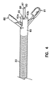
- the distal end 16 of the optical forceps includes a yoke 60, which serves as a mounting member for the cutting jaws.
- Yoke 60 may be machined from stainless steel or formed of other suitable material. It generally has a proximal portion or section indicated by reference number 61, a center section 62, and a distal section 63 having inwardly curved opposing distal end portions 63a and 63b.
- Yoke 60 has a bore 64 running therethrough.
- Each of the opposing distal end portions 63a and 63b has an arc shaped groove 65 (Figs. 5B and 5C) formed therein which defines a guide slot for the distal end of the fiber 50.
- the diameter of the bore defined by the arcuate grooves 65 can be stepped to a smaller size at distal end portions 63a and 63b.
- Sections 61 and 62 are generally circular in section. Section 61 has a diameter corresponding to the inside dimension of coil 22, while section 62 has a diameter corresponding to the outside dimension of coil 22, so that the end of coil 22 may be received and bonded to section 61.
- the proximal end surface 56 of the yoke 60 cooperates with the distal end 21 of the inner tube 20 to provide a limit stop for the fiber tube assembly 52 when it is being advanced within the outer tube 22 to open the jaws.
- Center section 62 has a pair of holes 68, 69 which receive pins 72, 73 to hold the jaws in place.
- Distal section 63 is stepped down relative to section 62, as seen in side view in Figs. 2 and 5B, to allow the jaws 80 and 81 to fold against it when the jaws are closed (Fig. 3) so as to have a thin profile for ease of introduction and navigation.
- Distal section 63 also has a vertical slot 70 provided therein which is dimensioned to the size of the mounting ends of the lever arms 85 of the jaws.
- the inner wall 71 of distal section 63 is stepped outwardly relative to the slot 70 to provide clearance for the ends of control wires 40 and 41.
- jaw 80 and 81 are similar only one is described in detail here.
- the two jaws are mirror-image identical, but with their serrations staggered so that they will mesh.
- jaw 80 has a rearward lever or mounting portion 85, and a distal cup or sample receiving portion 82, which has sharp serrations 83 used to cut the tissue sample.
- the lever portion 85 has a hole 84 formed to receive the pin 72 which thus serves to retain the jaws, and also to acts as the pivot point.
- a hole 86 is provided at the forward apex of the relieved section, to receive the end of control wire 40 (or 41) which is crimped or bent at a right angle at its tip to be effectively captured.
- the control wires are formed of wire which is stiff enough to push against the jaws to open them, but flexible enough to flex as the wires are retracted to pull the jaws together.
- the distal end 16 of the optical forceps also includes a fiber tube assembly 52. It includes a tube 54 which may be machined from stainless steel, or formed of other suitable material. The end of plastic tube 20 overlaps end 55 of the tube 54 and is bonded to tube 54. The control wires 40, 41 and the optical fiber 50 pass into it from the plastic tube 20. The optical fiber and the control wires pass axially through the tube 54 and are bonded to the tube 54 by epoxy or other suitable adhesive.
- the optical fiber 50 includes a jacket 87 of polyamide or similar material and an outer protective tube 88 made of stainless steel, for example. The jacket 87 extends the length of the optical fiber from its proximal end to its proximal end.
- the protective tube 88 extends from the distal end of the optical fiber to at least a point located within the distal end of tube 54.
- the distal end of the optical fiber 50 is flush with the end of the protective tube 88, and may have a lens or clear epoxy coating, depending on the optical properties desired.
- the protective tube 88 at the distal end of the optical fiber is designed to give strength to prevent damage to the fiber by tweezers and the like when tissue is removed from the biopsy jaws.
- the slider 30 in operation, is retracted toward the back of handle 12 to close the jaws. This causes movement (to the left in Fig. 2) of plastic tube 20, the fiber tube assembly 52, the control wires 40, 41, and the optical fiber 50. This retracts the optical fiber into the yoke 60 and the pulling of the control wires closes the jaws.
- the distal end is of the same narrow diameter as the main body of the forceps catheter, and the closed jaws have a smooth, rounded shape to facilitate introduction and navigation in the vascular, endoscopic or laproscopic systems.
- the cutting jaws are coaxially positioned with respect to the distal end of the optical fiber.
- the forceps jaws can be opened by pushing slider 30 of the control handle forward. This causes movement (to the right in Fig. 2) of plastic tube 20, the fiber tube assembly 52, the control wires 40, 41, and the optical fiber 50.
- the control wires push against the jaws, causing them to open.
- the tip of the optical fiber is axially extended.
- the distal end or tip of the optical fiber is positioned at the distal end of the catheter body with its optical view axis or view axis aligned for a tissue analysis zone adjacent the distal tip of the catheter body and positioned at the area of contact of the cutting jaws when the cutting jaws are operated to their closed cutting position.
- the device may then be used for optical tissue identification.
- slider 30 When an area of disease is identified and a biopsy of it is needed, slider 30 is pulled, retracting the tip of the fiber and simultaneously causing the jaws to close and cut a biopsy sample at the exact place being viewed by the fiber.
- the biopsy sample is cut from the exact tissue site identified by the spectroscopic analysis step without requiring moving or repositioning of the catheter body.
- the forceps may then be withdrawn from the patient to recover the sample for analysis.
- the analysis of the withdrawn sample can be conducted using known laboratory techniques to confirm the identification of the tissue sample made by spectroscopic analysis.
- the optical biopsy forceps of the invention is used for spectroscopically analyzing tissue in the tissue analysis zone adjacent the distal end of the forceps through the use of an electro-optic tissue analysis system connected to the proximal end of the optical fiber.
- the optical biopsy forceps are guided spectroscopically within the body to an area of interest as identified by the spectroscopic analysis of tissue type in the tissue analysis zone adjacent the distal tip of the catheter body.
- FIG. 7 another embodiment of an integrated optical biopsy forceps of the present invention is generally indicated by reference number 90.
- the optical forceps 90 is generally similar to the optical forceps 10 shown in Fig. 1, and accordingly, corresponding elements have been given the same reference number.
- the optical biopsy forceps is adapted for use internally in the body, for example in connection with endoscopic, laparoscopic or vascular procedures.
- Forceps 90 includes a handle portion 91 and an operating lever 92 at the proximal end, a middle portion 14 which extends over the main length of the device, and a distal end 16.
- the distal end 16 includes forceps cutting jaws 80 and 81 and the distal end of the optical fiber 50 which is contained within a plastic tube, corresponding to plastic tube 20 of forceps 10, and pass through a sleeve 24 in the manner illustrated in Figs. 1-6 for the forceps 10.
- the operating lever 92 has its upper end 93 pivoted to the handle 91 by a pivot pin 94.
- the forceps 90 includes a reinforcing tube, corresponding to reinforcing tube 29 of forceps 10, which encloses the fiber optical tube, and control wires 40 and 41.
- the control wires pass around a post 95 and are secured to the operating lever 92 near its upper end 93 located within the handle.
- the optical fiber tube extends out of the handle in a protective sheath 32 as described above with reference to optical biopsy forceps 10.
- Loops 97 are provided in the handle 91 and the operating lever 92, forming finger holes useful in grasping and manipulating the forceps.
- the operating lever also has curved regions 99 forming finger rests, which together with the depending operating lever arrangement of the forceps 90, enhance the ergonomics of the instrument.
- the jaws 80 and 81 are open when the relative position between the handle 91 and the operating lever 92 is as illustrated in Fig. 6.
- the control wires 40 and 41 are drawn around the post 95, retracting the optical fiber and operating the jaws 80 and 81 closed in a manner similar to that described for the operation of forceps 10.
- the control wires are advanced within tube 20, causing the jaws to open.
- the optical biopsy forceps includes an optical fiber 150 and opposed forceps cutting jaws 180 and 181, which can be similar to the optical fiber and the jaws of forceps 10 shown in figs. 1-6.
- the optical fiber 150 of the optical biopsy forceps includes an outer tubular, sheath-like member or catheter body 110, which corresponds to the outer sheath or coil 22 (Fig. 2), and a reinforcement cover 116, which, for example, can be a metal coil or cable, a nylon sheath, or any other suitable cover.
- the reinforced optical fiber is movable axially within the sheath 110.
- the optical biopsy forceps further includes a tubular slide member connected to the optical fiber and movable therewith, and coupled to the jaws 180 and 181 for actuating the jaws 180 and 181 as the optical fiber is moved within the outer sheath 110.
- the optical biopsy forceps includes a suitable handle (not shown) for facilitating actuation of the tubular slide member 120.
- the handle is similar to the handle 12 (Fig. 1) of the optical biopsy forceps 10, but the handle can include any type of actuating mechanism capable of imparting bidirectional axial movement to the optical fiber 150 of the optical biopsy forceps.
- the optical fiber 150 positioned within the outer sheath extends over the main length of the device, from the distal end 106 to the handle.
- the proximal end of the sheath 110 passes through a sleeve, such as sleeve 24, and is secured to the tip of the handle.
- the sleeve provides reinforcement and strain relief where the sheath 110 is attached to the handle.
- the proximal end of the optical fiber 150 also passes through sleeve 24 and is secured to the slider 30 of the handle 12 distally of the proximal end of the optical fiber 150, the end portion of which passes through the slider and out of the handle for connection to suitable electro-optical units in the manner that has been described for the optical fiber 50 of optical biopsy forceps 10.
- the slider 30 of the handle is adapted to push the reinforced optical fiber 150, which in turn pushes the tubular slide member 120, to open the jaws of the optical biopsy forceps and to pull the reinforced optical fiber, pulling the tubular slide member 120, to close the jaws.
- the optical biopsy forceps of the present invention can be used with any type of electro-optical technique for guiding the forceps.
- This may include systems which use viewing or imaging, systems which use illumination with white light to excite dyes in the area of interest, and spectroscopic techniques to identify tissue types by spectral analysis of light returned from tissue illuminated with light of certain wavelengths.
- spectroscopic techniques utilize the property of certain tissue types to reflect or fluoresce light having characteristic wavelengths.
- the sheath 110 is a flexible hollow catheter which can be made a plastic tube, or a plastic/metal composite structure that defines an opening or bore therethrough.
- the outer sheath 110 can be similar to those of disposable biopsy forceps commonly used with colonoscopes used in the upper and lower gastrointestinal tracts, and broncoscopes used in the trachea and bronchus.
- the outer sheath 110 can be a rigid tube, such as those of biopsy forceps commonly used with cystoscopes, colposcopes and laproscopes.
- the optical fiber 150 extends through a central bore 119 formed through a tubular slide member 120 which, in turn, is mounted in a mounting member or jaw support block 122 which serves as a mounting member for the cutting jaws 180, 181.
- the jaw support block 122 can be machined from stainless steel or formed of other suitable material.
- the jaw support block 122 has a bore 124 running therethrough which is generally circular in section.
- the inner dimension of the jaw support block 122 corresponds to the outer dimension of the outer sheath 110 which is secured to the support block in a suitable manner, such as with cement or by crimping.
- the jaws 180, 181 are hinged to the support block 122 which has a pair of holes which receive pins 130, 132 which pass through ears 134 of the jaws to hold the jaws 180, 181 in place.
- the attachment of the jaws to the support block by ears 134 allows the jaws 180, 181 to fold against the front end of the support block when closed so as to have a thin profile for the distal end of the forceps for ease of introduction and navigation.
- the jaw support block 122 has a slot to control travel of the jaws 180 and 181.
- the tubular slide member 120 is mounted in the bore 124 in the jaw support block 122 and is free to move axially within support block 122 during actuation of the jaws.
- the fiber 150 is secured to the tubular slide member 120 in a suitable manner such as with cement.
- the jaws 180, 181 are connected to the tubular slide member 120 by a pair of control links 136, 138, which are rigid members that function as a linkage mechanism connecting the cutting jaws to the tubular slide member.
- Control link 136 has one end 139 connected to tubular slide member 120 by a pin 140.
- the other end 141 of the control link 136 is connected to jaw 180 by a pin 142.
- control link 138 has one end 144 connected to tubular slide member 120 by a pin 146 and its other end 148 connected to jaw 181 by a pin 149.
- axial movement of the optical fiber in the direction of arrow 154 causes axial movement of tubular slide member 120, pivoting the control links 136, 138, about their ends 139 and 144, respectively, drawing the jaws together to actuate the cutting jaws 180, 181.
- the rearward surface 151 at the distal end 152 of the tubular slide member 120 is adapted to engage the forward surface 153 of the jaw support block 122, functioning as a travel limit stop surface to limit the axial movement of the tubular slide member 120 during retraction of the optical fiber 150.
- both the proximal and distal ends of the tubular slide member 120 include limit stops which prevent both over distention and over retraction of the optical fiber 150.
- the optical fiber 150 is fully retracted (by retracting the slider 30 toward the back of the handle) to move the tubular slide member 120 in the direction of the arrow 154 until its rearward surface 151 engages forward surface 152 of the jaw support block 122.
- the control links 136 and 138 have been drawn rearwardly, drawing the jaws 180, 181 together so that the jaws are closed.
- the distal end 106 of the forceps is substantially of the same narrow diameter as the outer sheath 116 which defines the main body portion of the optical biopsy forceps, and the closed jaws have a smooth, rounded shape to facilitate introduction and navigation through the biopsy channel of an endoscope, for example
- the endoscopist advances the optical biopsy forceps through the biopsy channel of the endoscope to the general area of interest, i.e., such as a tissue site or tissue analysis zone with a body, represented by the reference numeral 170.
- the forceps jaws can be opened by advancing the slider 30, thereby advancing the optical fiber 150 forwardly through the handle. This causes the tubular slide member 120 to move forwardly (to the right in Fig. 8), which in turn causes pivoting of the control links 136 and 138. As the control links pivot, the control links push against the jaws, causing the jaws to open. Simultaneously, the distal tip of the optical fiber 150 is axially extended forwardly beyond the jaws. The forceps may then be used for optical tissue identification.
- the slider 30 When an area of disease is identified and if a biopsy of it is needed, the slider 30 is retracted, retracting the optical fiber 150 and thus the tubular slide member 120, retracting the tip of the optical fiber and simultaneously causing the jaws to close and cut a biopsy sample at the exact place that has been located by viewing through the optical fiber.
- the endoscopist holding the instrument by the handle gently pulls back on the slider of the handle, retracting the optical fiber and tubular slide member 120, moving the optical fiber away from the tissue surface.
- the jaws begin to close as the tubular slide member is moved in the direction of the arrow 154.
- the endoscopist gently pushes on the instrument to urge the jaws towards the tissue surface so that a tissue sample will be captured by the jaws as they close.
- the endoscopist pulls the entire assembly away from the tissue surface and then withdraws the optical biopsy forceps from the endoscope so that the specimen tissue can be retrieved.
- the present invention has provided an optical biopsy forceps.
- An important feature of the invention is that the tip of the optical fiber 50 (and optical fiber 150) is coaxial with, and perfectly aligned with, the zone where the two jaws 80, 81 (and jaws 180, 181) intersect and the sample is taken.
- This, together with the slim and compact profile of the device when the jaws are retracted, is a great improvement over prior art devices.
- the fiber optic assembly including the optical fiber and the tubular slide member of the biopsy forceps, can be produced as a disposable assembly, with the rest of the biopsy forceps being produced as a non-disposable unit.
- the major advantage of forceps 100 as compared to forceps 10 is, because the biopsy jaw control wires 40, 41 are not required, larger diameter optical fibers can be used to increase the detected signal relative to noise.
Landscapes
- Health & Medical Sciences (AREA)
- Life Sciences & Earth Sciences (AREA)
- Surgery (AREA)
- Heart & Thoracic Surgery (AREA)
- Molecular Biology (AREA)
- Pathology (AREA)
- Engineering & Computer Science (AREA)
- Biomedical Technology (AREA)
- Biodiversity & Conservation Biology (AREA)
- Medical Informatics (AREA)
- Nuclear Medicine, Radiotherapy & Molecular Imaging (AREA)
- Animal Behavior & Ethology (AREA)
- General Health & Medical Sciences (AREA)
- Public Health (AREA)
- Veterinary Medicine (AREA)
- Endoscopes (AREA)
- Surgical Instruments (AREA)
- Medicines Containing Plant Substances (AREA)
Claims (10)
- Integrierte optische Biopsiezange, aufweisend:einen flexiblen Katheterkörper (22) mit einer hindurchtretenden Öffnung sowie mit einem proximalen und einem distalen Ende,eine optische Faser (50), die durch den Katheterkörper (22) hindurch verläuft und an ihrem proximalen Ende zur Verbindung mit einem elektrooptischen Gewebeanalysesystem eingerichtet ist, wobei das distale Ende der optischen Faser am distalen Ende des Katheterkörpers angeordnet ist und eine optische Beobachtungsachse aufweist und wobei das distale Ende der optischen Faser und die optische Beobachtungsachse auf eine Gewebeanalysezone beim distalen Ende des Katheterkörpers ausgerichtet sind,Schneidbacken (80, 81), die zum wahlweisen Öffnen und Schließen in der Biopsieschneidbewegung am distalen Ende des Katheterkörpers befestigt sind, koaxial zur Beobachtungsachse angeordnet sind und eine geschlossene Schneidstellung auf der optischen Beobachtungsachse aufweisen und die Gewebeanalysezone umschließen, undeinen Aktormechanismus (27, 30), der betriebsmäßig mit den Schneidbacken verbunden ist und zum wahlweisen Steuern des Öffnens und Schließens der Schneidbacken vom proximalen Ende aus, um eine Biopsieprobe am exakten Ort der Gewebeanalysezone auszuschneiden, am proximalen Ende des Katheterkörpers befestigt ist und Steuerdrähte (40, 41) aufweist, die zum Öffnen und Schließen der Schneidbacken durch ihre Axialbewegung mit den Schneidbacken verbunden sind,dadurch gekennzeichnet, daß der Aktormechanismus das distale Ende der optischen Faser (50) einzieht, wenn sich die Schneidbacken gegeneinander schließen.
- Zange nach Anspruch 1, wobei der Katheterkörper ein mit der optischen Faser (50) verbundenes Tubuselement (29) beinhaltet und der Aktormechanismus einen an einem Griff (12) relativ zu diesem beweglich befestigten Schlitten (30) enthält, wobei die Steuerdrähte (40, 41) am Schlitten befestigt sind, der eingerichtet ist, differntiell das Tubuselement zu schieben, um die Schneidbacken zu öffnen und das distale Ende der optischen Faser (50) auszufahren, und die Steuerdrähte und das Tubuselement zu ziehen, um das distale Ende der optischen Faser einzuziehen und die Schneidbacken zu schließen, während eine Biopsieprobe genommen wird.
- Zange nach Anspruch 1, wobei der flexible Katheterkörper koaxial zueinander ein inneres (20) und ein äußeres (22) Tubuselement aufweist, die zwischen dem proximalen und dem distalen Ende der Zange verlaufen,
wobei am distalen Ende der Zange ein Befestigungselement (60) mit dem äußeren Tubuselement (22) verbunden ist, um die Backen (80, 81) zum selektiven Öffnen und Schließen in der Biopsieschneidbewegung zu befestigen,
die optische Faser (50) durch das innere Tubuselement (20) des Katheterkörpers verläuft,
am proximalen Ende der Zange ein Steuergriff (12) vorhanden ist, der das proximale Ende der optischen Faser zu ihrer Verbindung mit dem elektrooptischen Gewebeanalysesystem aufnimmt und das innere und das äußere Tubuselement und die Steuerdrähte aufnimmt, und
der Steuergriff eine Aktorsteuerung (26, 30) aufweist, um differentiell das äußere Tubuselement zu schieben und die Steuerdrähte und das innere Tubuselement zu ziehen, um das distale Ende der optischen Faser einzuziehen und die Schneidbacken zu schließen und dadurch eine Biopsieprobe am exakten Beobachtungsbereich der optischen Gewebeanalyse zu nehmen. - Zange nach Anspruch 3, wobei der Aktormechanismus einen Schlitten (30) enthält, der am Griff relativ zu diesem beweglich befestigt ist und an dem die Steuerdrähte befestigt sind und der zum Schließen der Backen die Steuerdrähte ziehen und zum Öffnen der Backen das innere Tubuselement schieben kann.
- Zange nach Anspruch 3, wobei das innere Tubuselement einen distalen Tubusabschnitt (52) beinhaltet, der mit der optischen Faser verbunden und in Axialrichtung des Katheterkörpers bewegbar ist.
- Zange nach Anspruch 5, wobei das distale Ende des inneren Tubuselements (20) zur Zusammenwirkung mit dem Befestigungselement (60) eingerichtet ist, um für den distalen Tubusabschnitt und die damit verbundene optische Faser einen Begrenzungsanschlag zu bilden.
- Zange nach Anspruch 1, mit einem inneren Tubuselement (20), das dort von einem äußeren Tubuselement (22) aufgenommen ist, wo die optische Faser (50) in ihm angeordnet ist und durch den Katheterkörper verläuft.
- Zange nach Anspruch 7, wobei das äußere Tubuselement (22) eine Spule und das innere Tubuselement (20) ein Tubus ist.
- Zange nach Anspruch 7, wobei das innere Tubuselement (20) zum äußeren Tubuselement (22) koaxial ist.
- Zange nach Anspruch 7, wobei die Schneidbacken (80, 81) eingerichtet sind, das innere Tubuselement hindurchtretend aufzunehmen.
Applications Claiming Priority (3)
| Application Number | Priority Date | Filing Date | Title |
|---|---|---|---|
| US08/644,080 US5762613A (en) | 1996-05-07 | 1996-05-07 | Optical biopsy forceps |
| US644080 | 1996-05-07 | ||
| PCT/US1997/007624 WO1997041776A1 (en) | 1996-05-07 | 1997-05-07 | Optical biopsy forceps |
Publications (2)
| Publication Number | Publication Date |
|---|---|
| EP0910284A1 EP0910284A1 (de) | 1999-04-28 |
| EP0910284B1 true EP0910284B1 (de) | 2007-01-24 |
Family
ID=24583369
Family Applications (1)
| Application Number | Title | Priority Date | Filing Date |
|---|---|---|---|
| EP97922685A Expired - Lifetime EP0910284B1 (de) | 1996-05-07 | 1997-05-07 | Zange für optische biopsie |
Country Status (7)
| Country | Link |
|---|---|
| US (2) | US5762613A (de) |
| EP (1) | EP0910284B1 (de) |
| JP (1) | JP3220164B2 (de) |
| AT (1) | ATE352256T1 (de) |
| CA (1) | CA2253643C (de) |
| DE (1) | DE69737289T2 (de) |
| WO (1) | WO1997041776A1 (de) |
Cited By (10)
| Publication number | Priority date | Publication date | Assignee | Title |
|---|---|---|---|---|
| US7952718B2 (en) | 2007-05-03 | 2011-05-31 | University Of Washington | High resolution optical coherence tomography based imaging for intraluminal and interstitial use implemented with a reduced form factor |
| WO2012149643A1 (en) * | 2011-05-04 | 2012-11-08 | George Klein | Ablation grasper |
| US8382662B2 (en) | 2003-12-12 | 2013-02-26 | University Of Washington | Catheterscope 3D guidance and interface system |
| US8396535B2 (en) | 2000-06-19 | 2013-03-12 | University Of Washington | Integrated optical scanning image acquisition and display |
| US8537203B2 (en) | 2005-11-23 | 2013-09-17 | University Of Washington | Scanning beam with variable sequential framing using interrupted scanning resonance |
| US8840566B2 (en) | 2007-04-02 | 2014-09-23 | University Of Washington | Catheter with imaging capability acts as guidewire for cannula tools |
| US9161684B2 (en) | 2005-02-28 | 2015-10-20 | University Of Washington | Monitoring disposition of tethered capsule endoscope in esophagus |
| US9561078B2 (en) | 2006-03-03 | 2017-02-07 | University Of Washington | Multi-cladding optical fiber scanner |
| US10405838B2 (en) | 2014-08-28 | 2019-09-10 | Koninklijke Philips N.V. | Side-looking lung biopsy device |
| EP2519300B1 (de) | 2009-12-29 | 2020-08-12 | Acclarent, Inc. | System zur behandlung von zielgewebe in der eustachischen röhre |
Families Citing this family (139)
| Publication number | Priority date | Publication date | Assignee | Title |
|---|---|---|---|---|
| US6485413B1 (en) | 1991-04-29 | 2002-11-26 | The General Hospital Corporation | Methods and apparatus for forward-directed optical scanning instruments |
| US6564087B1 (en) | 1991-04-29 | 2003-05-13 | Massachusetts Institute Of Technology | Fiber optic needle probes for optical coherence tomography imaging |
| US6111645A (en) | 1991-04-29 | 2000-08-29 | Massachusetts Institute Of Technology | Grating based phase control optical delay line |
| US5762613A (en) * | 1996-05-07 | 1998-06-09 | Spectrascience, Inc. | Optical biopsy forceps |
| US6296608B1 (en) * | 1996-07-08 | 2001-10-02 | Boston Scientific Corporation | Diagnosing and performing interventional procedures on tissue in vivo |
| US6508825B1 (en) | 1997-02-28 | 2003-01-21 | Lumend, Inc. | Apparatus for treating vascular occlusions |
| US6217549B1 (en) | 1997-02-28 | 2001-04-17 | Lumend, Inc. | Methods and apparatus for treating vascular occlusions |
| CA2283949A1 (en) | 1997-03-13 | 1998-09-17 | Haishan Zeng | Methods and apparatus for detecting the rejection of transplanted tissue |
| AU6604898A (en) * | 1997-03-13 | 1998-09-29 | Biomax Technologies, Inc. | Catheters and endoscopes comprising optical probes and bioptomes and methods of using the same |
| US6368327B2 (en) * | 1997-04-29 | 2002-04-09 | Raymond F. Lippitt | Medical device |
| US5961458A (en) * | 1997-11-18 | 1999-10-05 | Carewise Medical Products Corporation | Minimally invasive surgical probe for tissue identification and retrieval and method of use |
| US6484050B1 (en) * | 1997-11-18 | 2002-11-19 | Care Wise Medical Products Corporation | Minimally invasive surgical instrument for tissue identification, dislodgment and retrieval and methods of use |
| US6066102A (en) | 1998-03-09 | 2000-05-23 | Spectrascience, Inc. | Optical biopsy forceps system and method of diagnosing tissue |
| US6174291B1 (en) | 1998-03-09 | 2001-01-16 | Spectrascience, Inc. | Optical biopsy system and methods for tissue diagnosis |
| US6284223B1 (en) * | 1998-10-15 | 2001-09-04 | Fluoroprobe, Inc. | Method for viewing tumor tissue located within a body cavity |
| US6652836B2 (en) | 1998-10-15 | 2003-11-25 | Fluoroprobe, Inc. | Method for viewing tumor tissue located within a body cavity |
| US6299860B1 (en) * | 1998-10-15 | 2001-10-09 | Fluoro Probe, Inc. | Method for viewing diseased tissue located within a body cavity |
| US6248124B1 (en) * | 1999-02-22 | 2001-06-19 | Tyco Healthcare Group | Arterial hole closure apparatus |
| US6445939B1 (en) | 1999-08-09 | 2002-09-03 | Lightlab Imaging, Llc | Ultra-small optical probes, imaging optics, and methods for using same |
| US6308092B1 (en) * | 1999-10-13 | 2001-10-23 | C. R. Bard Inc. | Optical fiber tissue localization device |
| JP3655785B2 (ja) * | 1999-10-18 | 2005-06-02 | ペンタックス株式会社 | 内視鏡用処置具 |
| ITCE990004A1 (it) | 1999-10-25 | 2000-01-25 | Mario Immacolato Paternuosto | Valve per pinza da biopsia in endoscopia digestiva |
| US6416519B1 (en) * | 1999-11-15 | 2002-07-09 | Vandusseldorp Gregg A. | Surgical extraction device |
| US8888688B2 (en) | 2000-04-03 | 2014-11-18 | Intuitive Surgical Operations, Inc. | Connector device for a controllable instrument |
| US6610007B2 (en) | 2000-04-03 | 2003-08-26 | Neoguide Systems, Inc. | Steerable segmented endoscope and method of insertion |
| US6858005B2 (en) * | 2000-04-03 | 2005-02-22 | Neo Guide Systems, Inc. | Tendon-driven endoscope and methods of insertion |
| US6468203B2 (en) | 2000-04-03 | 2002-10-22 | Neoguide Systems, Inc. | Steerable endoscope and improved method of insertion |
| US8517923B2 (en) | 2000-04-03 | 2013-08-27 | Intuitive Surgical Operations, Inc. | Apparatus and methods for facilitating treatment of tissue via improved delivery of energy based and non-energy based modalities |
| WO2002032330A2 (en) * | 2000-10-16 | 2002-04-25 | Lumend, Inc. | Catheter for treating a vascular occlusion |
| US20050010235A1 (en) * | 2003-07-09 | 2005-01-13 | Vandusseldorp Gregg A. | Surgical device |
| US7232445B2 (en) * | 2000-12-06 | 2007-06-19 | Id, Llc | Apparatus for the endoluminal treatment of gastroesophageal reflux disease (GERD) |
| US6716226B2 (en) * | 2001-06-25 | 2004-04-06 | Inscope Development, Llc | Surgical clip |
| US20020068945A1 (en) * | 2000-12-06 | 2002-06-06 | Robert Sixto | Surgical clips particularly useful in the endoluminal treatment of gastroesophageal reflux disease (GERD) |
| US20020138086A1 (en) * | 2000-12-06 | 2002-09-26 | Robert Sixto | Surgical clips particularly useful in the endoluminal treatment of gastroesophageal reflux disease (GERD) |
| US7727246B2 (en) * | 2000-12-06 | 2010-06-01 | Ethicon Endo-Surgery, Inc. | Methods for endoluminal treatment |
| US8062314B2 (en) * | 2000-12-06 | 2011-11-22 | Ethicon Endo-Surgery, Inc. | Methods for the endoluminal treatment of gastroesophageal reflux disease (GERD) |
| IL140136A (en) * | 2000-12-06 | 2010-06-16 | Intumed Ltd | Apparatus for self-guided intubation |
| WO2002064020A2 (en) * | 2001-02-13 | 2002-08-22 | Lumend, Inc. | Method and apparatus for micro-dissection of vascular occlusions |
| JP4295925B2 (ja) * | 2001-03-01 | 2009-07-15 | Hoya株式会社 | 内視鏡用バイポーラ高周波処置具 |
| US6808491B2 (en) | 2001-05-21 | 2004-10-26 | Syntheon, Llc | Methods and apparatus for on-endoscope instruments having end effectors and combinations of on-endoscope and through-endoscope instruments |
| JP5073895B2 (ja) * | 2001-09-25 | 2012-11-14 | オリンパス株式会社 | 内視鏡用処置具 |
| EP1469777A4 (de) | 2002-01-09 | 2007-04-04 | Neoguide Systems Inc | Gerät und verfahren für die spektroskopische untersuchung des kolon |
| CN1764416A (zh) | 2002-01-09 | 2006-04-26 | 新引导系统公司 | 用于内窥镜结肠切除术的设备和方法 |
| JP4131011B2 (ja) * | 2002-04-09 | 2008-08-13 | Hoya株式会社 | 内視鏡用嘴状処置具 |
| US20030225432A1 (en) * | 2002-05-31 | 2003-12-04 | Baptiste Reginald C. | Soft tissue retraction device for an endoscopic instrument |
| JP4420593B2 (ja) * | 2002-07-29 | 2010-02-24 | Hoya株式会社 | 内視鏡用バイポーラ型高周波処置具 |
| DE10255082A1 (de) * | 2002-11-20 | 2004-06-17 | Aesculap Ag & Co. Kg | Endoskop |
| DE10258483B3 (de) * | 2002-12-10 | 2004-06-17 | Universitätsklinikum Charité, Medizinische Fakultät der Humboldt-Universität zu Berlin | Optisches Biopsieinstrument |
| US8882657B2 (en) | 2003-03-07 | 2014-11-11 | Intuitive Surgical Operations, Inc. | Instrument having radio frequency identification systems and methods for use |
| JP4131014B2 (ja) * | 2003-03-18 | 2008-08-13 | Hoya株式会社 | 内視鏡用嘴状処置具 |
| ATE427131T1 (de) * | 2003-06-10 | 2009-04-15 | Lumend Inc | Kathetersystem und verfahren zum íffnen von okklusionen der blutgefasse |
| US20040260337A1 (en) * | 2003-06-18 | 2004-12-23 | Scimed Life Systems, Inc. | Endoscopic instruments and methods of manufacture |
| US8469993B2 (en) | 2003-06-18 | 2013-06-25 | Boston Scientific Scimed, Inc. | Endoscopic instruments |
| USD545432S1 (en) * | 2003-08-08 | 2007-06-26 | Olympus Corporation | Distal portion of hemostatic forceps for endoscope |
| US7775989B2 (en) * | 2003-09-03 | 2010-08-17 | Granit Medical Innovations, Llc | Needle biopsy forceps with integral sample ejector |
| JP4593096B2 (ja) * | 2003-09-09 | 2010-12-08 | オリンパス株式会社 | 内視鏡用処置具 |
| EP2455016B1 (de) * | 2003-09-09 | 2014-06-18 | Olympus Corporation | Endoskop-Behandlungswerkzeug |
| US7588545B2 (en) | 2003-09-10 | 2009-09-15 | Boston Scientific Scimed, Inc. | Forceps and collection assembly with accompanying mechanisms and related methods of use |
| US7942896B2 (en) * | 2003-11-25 | 2011-05-17 | Scimed Life Systems, Inc. | Forceps and collection assembly and related methods of use and manufacture |
| USD590944S1 (en) | 2004-02-06 | 2009-04-21 | Olympus Corporation | Distal portion of hemostatic forceps for endoscope |
| CA2558796C (en) * | 2004-03-23 | 2016-10-04 | Boston Scientific Limited | In-vivo visualization system |
| US11819192B2 (en) | 2004-03-23 | 2023-11-21 | Boston Scientific Scimed, Inc. | In-vivo visualization system |
| US9968290B2 (en) * | 2004-06-30 | 2018-05-15 | Given Imaging Ltd. | Apparatus and methods for capsule endoscopy of the esophagus |
| EP1838229B1 (de) * | 2005-01-20 | 2009-08-26 | Wilson-Cook Medical Inc. | Biopsiezange |
| CA2595459C (en) * | 2005-01-21 | 2013-11-26 | Mayo Foundation For Medical Education And Research | Thorascopic heart valve repair method and apparatus |
| US8287535B2 (en) * | 2005-05-11 | 2012-10-16 | Mayo Foundation For Medical Education And Research | Apparatus and methods for internal surgical procedures |
| US7762960B2 (en) | 2005-05-13 | 2010-07-27 | Boston Scientific Scimed, Inc. | Biopsy forceps assemblies |
| JP4880251B2 (ja) * | 2005-06-21 | 2012-02-22 | オリンパスメディカルシステムズ株式会社 | 高周波処置具 |
| US7658708B2 (en) * | 2005-09-20 | 2010-02-09 | Ai Medical Devices, Inc. | Endotracheal intubation device |
| WO2007050683A2 (en) * | 2005-10-24 | 2007-05-03 | Spectrascience, Inc. | System and method for non-endoscopic optical biopsy detection of diseased tissue |
| EP3788944B1 (de) | 2005-11-22 | 2024-02-28 | Intuitive Surgical Operations, Inc. | System zur bestimmung der form eines biegbaren instruments |
| WO2007062066A2 (en) | 2005-11-23 | 2007-05-31 | Neoguide Systems, Inc. | Non-metallic, multi-strand control cable for steerable instruments |
| US20070244510A1 (en) | 2006-04-14 | 2007-10-18 | Ethicon Endo-Surgery, Inc. | Endoscopic device |
| US7857827B2 (en) | 2006-04-14 | 2010-12-28 | Ethicon Endo-Surgery, Inc. | Endoscopic device |
| US7998167B2 (en) | 2006-04-14 | 2011-08-16 | Ethicon Endo-Surgery, Inc. | End effector and method of manufacture |
| WO2007137208A2 (en) | 2006-05-19 | 2007-11-29 | Neoguide Systems, Inc. | Methods and apparatus for displaying three-dimensional orientation of a steerable distal tip of an endoscope |
| DE102006028001B4 (de) * | 2006-06-14 | 2009-11-26 | Paul Peschke Gmbh | Chirurgische Greifzange |
| US8114121B2 (en) | 2006-06-22 | 2012-02-14 | Tyco Healthcare Group Lp | Tissue vitality comparator with light pipe with fiber optic imaging bundle |
| AU2007275720A1 (en) * | 2006-07-18 | 2008-01-24 | Boston Medical Center Corporation | Device with integrated multi-fiber optical probe and methods of use |
| US20080045859A1 (en) * | 2006-08-19 | 2008-02-21 | Fritsch Michael H | Devices and Methods for In-Vivo Pathology Diagnosis |
| US20080097519A1 (en) * | 2006-10-20 | 2008-04-24 | Alfred E. Mann Foundation For Scientific Research | Medical device extraction tool |
| JP4526544B2 (ja) * | 2007-02-08 | 2010-08-18 | オリンパスメディカルシステムズ株式会社 | 内視鏡用処置具 |
| EP1955657B1 (de) * | 2007-02-08 | 2011-01-12 | Olympus Medical Systems Corp. | Endoskop-Behandlungswerkzeug |
| CN101686828A (zh) * | 2007-02-19 | 2010-03-31 | 多种活检标本有限责任公司 | 用于获取一个或多个样本的活检钳 |
| EP1985329B1 (de) * | 2007-04-25 | 2010-06-02 | Olympus Medical Systems Corp. | Rohrförmiges Element und endoskopisches Instrument |
| AU2008302345A1 (en) * | 2007-09-19 | 2009-03-26 | Oncofluor, Inc. | Method for imaging and treating organs and tissues |
| US9220398B2 (en) | 2007-10-11 | 2015-12-29 | Intuitive Surgical Operations, Inc. | System for managing Bowden cables in articulating instruments |
| CN101902975B (zh) | 2007-10-18 | 2014-06-04 | 尼奥绰德有限公司 | 搏动心脏中瓣膜小叶的微创修复 |
| WO2009060460A2 (en) * | 2007-11-09 | 2009-05-14 | Given Imaging Ltd. | Apparatus and methods for capsule endoscopy of the esophagus |
| CA2709916C (en) * | 2007-12-18 | 2016-07-19 | Bovie Medical Corporation | Surgical apparatus with removable tool cartridge |
| JP5818438B2 (ja) | 2007-12-21 | 2015-11-18 | スミス アンド ネフュー インコーポレーテッドSmith & Nephew,Inc. | 多数ポータルガイド |
| US9826992B2 (en) | 2007-12-21 | 2017-11-28 | Smith & Nephew, Inc. | Multiple portal guide |
| KR101583246B1 (ko) | 2008-02-06 | 2016-01-12 | 인튜어티브 서지컬 오퍼레이션즈 인코포레이티드 | 제동 능력을 가지고 있는 체절식 기구 |
| US8221418B2 (en) | 2008-02-07 | 2012-07-17 | Tyco Healthcare Group Lp | Endoscopic instrument for tissue identification |
| US8182418B2 (en) | 2008-02-25 | 2012-05-22 | Intuitive Surgical Operations, Inc. | Systems and methods for articulating an elongate body |
| WO2009111717A1 (en) * | 2008-03-06 | 2009-09-11 | Trustees Of Boston University | Low cost disposable medical forceps to enable a hollow central channel for various functionalities |
| CN102056559A (zh) * | 2008-06-12 | 2011-05-11 | 皇家飞利浦电子股份有限公司 | 具有声学元件的活检设备 |
| EP2346417A4 (de) | 2008-10-20 | 2017-04-26 | Spine View, Inc. | Retraktorkanülensystem für wirbelsäulenzugang und -visualisierung sowie entsprechende verfahren |
| US8267869B2 (en) * | 2008-12-31 | 2012-09-18 | Manua Kea Technologies | Multi-purpose biopsy forceps |
| US9433421B2 (en) * | 2010-03-12 | 2016-09-06 | Jms Co., Ltd. | Surgical tool for anastomosis |
| US9737320B2 (en) | 2010-03-18 | 2017-08-22 | Covidien Lp | Surgical grasper with integrated probe |
| AU2011245143B2 (en) * | 2010-04-30 | 2016-07-07 | Smith & Nephew, Inc. | Guide for drilling an irregular-shaped body |
| RU2013119074A (ru) | 2010-09-27 | 2014-11-10 | Смит Энд Нефью, Инк. | Устройство и способы его использования во время артроскопической операции |
| EP2635199A1 (de) | 2010-11-03 | 2013-09-11 | Smith & Nephew, Inc. | Bohrführung |
| US9044221B2 (en) | 2010-12-29 | 2015-06-02 | Neochord, Inc. | Exchangeable system for minimally invasive beating heart repair of heart valve leaflets |
| CN102232852A (zh) * | 2011-05-06 | 2011-11-09 | 潘文胜 | 利用光导纤维聚焦的活检钳 |
| WO2012167120A2 (en) | 2011-06-01 | 2012-12-06 | Neochord, Inc. | Minimally invasive repair of heart valve leaflets |
| CN102379727A (zh) * | 2011-09-02 | 2012-03-21 | 王宝根 | 多功能活检钳 |
| USD689606S1 (en) * | 2011-09-06 | 2013-09-10 | United States Endoscopy Group, Inc. | Rat tooth grasper assembly with identical jaws |
| WO2013056190A1 (en) * | 2011-10-15 | 2013-04-18 | Transmed7, Llc | Soft tissue coring biopsy devices and methods |
| DE102012109387A1 (de) * | 2012-10-02 | 2014-04-03 | Aesculap Ag | Chirurgisches Instrument und insbesondere elektrochirurgisches Instrument |
| US9592079B1 (en) * | 2013-03-14 | 2017-03-14 | Matt D. Pursley | Device and method for assisting removal of items endovascularly |
| CZ305616B6 (cs) | 2014-10-10 | 2016-01-06 | Oprox, A.S. | Katétr pro optickou biopsii |
| US20160256140A1 (en) * | 2015-03-03 | 2016-09-08 | United States Endoscopy Group, Inc. | Microforceps |
| USD758581S1 (en) | 2015-03-26 | 2016-06-07 | United States Endoscopy Group, Inc. | Grasper |
| USD779668S1 (en) | 2015-03-26 | 2017-02-21 | United States Endoscopy Group, Inc. | Grasper |
| JP2018510717A (ja) | 2015-03-26 | 2018-04-19 | ユナイテッド ステイツ エンドスコピー グループ,インコーポレイテッド | 内視鏡把持装置 |
| CA2975901C (en) | 2015-04-08 | 2020-06-30 | Synaptive Medical (Barbados) Inc. | Systems, devices and methods for tissue removal and analysis |
| US20160361051A1 (en) * | 2015-06-09 | 2016-12-15 | Boston Scientific Scimed, Inc. | System for the parallel delivery of an element into the esophageal mucosa |
| US20160367311A1 (en) * | 2015-06-16 | 2016-12-22 | Lawrence J. Gerrans | Instrumentation with Embedded Imaging Systems |
| WO2017059406A1 (en) | 2015-10-01 | 2017-04-06 | Neochord, Inc. | Ringless web for repair of heart valves |
| DK178989B1 (en) * | 2015-12-30 | 2017-07-31 | 3Dintegrated Aps | A surgical instrument assembly |
| US11135032B2 (en) | 2016-04-04 | 2021-10-05 | Gyrus Acmi, Inc. | Electrosurgical illuminating instrument |
| EP3448266B1 (de) | 2016-04-25 | 2024-06-12 | Claria Medical, Inc. | Vorrichtungen zur gewebeerfassung und -entnahme |
| US10213306B2 (en) | 2017-03-31 | 2019-02-26 | Neochord, Inc. | Minimally invasive heart valve repair in a beating heart |
| WO2019083896A1 (en) * | 2017-10-23 | 2019-05-02 | Claria Medical, Inc. | SYSTEMS AND METHODS FOR CATCHING AND REMOVING TISSUE |
| US10758214B2 (en) * | 2017-11-13 | 2020-09-01 | UVision360, Inc. | Biopsy device and method |
| US11896285B2 (en) | 2018-03-14 | 2024-02-13 | Gyrus Acmi, Inc. | Device with movable buttons or switches and visual indicator |
| AU2019238344B2 (en) | 2018-03-23 | 2021-06-24 | Neochord, Inc. | Device for suture attachment for minimally invasive heart valve repair |
| US11253360B2 (en) | 2018-05-09 | 2022-02-22 | Neochord, Inc. | Low profile tissue anchor for minimally invasive heart valve repair |
| US11173030B2 (en) | 2018-05-09 | 2021-11-16 | Neochord, Inc. | Suture length adjustment for minimally invasive heart valve repair |
| CA3112020C (en) | 2018-09-07 | 2023-10-03 | Neochord, Inc. | Device for suture attachment for minimally invasive heart valve repair |
| US11361918B2 (en) | 2019-03-25 | 2022-06-14 | Gyrus Acmi, Inc. | Device with movable buttons or switches and tactile identifier |
| US11376126B2 (en) | 2019-04-16 | 2022-07-05 | Neochord, Inc. | Transverse helical cardiac anchor for minimally invasive heart valve repair |
| US12208007B2 (en) | 2020-01-16 | 2025-01-28 | Neochord, Inc. | Helical cardiac anchors for minimally invasive heart valve repair |
| AU2022234898A1 (en) | 2021-03-12 | 2023-09-28 | Stryker European Operations Limited | Neurosurgical methods and systems for detecting and removing tumorous tissue |
| US12121221B2 (en) * | 2022-02-24 | 2024-10-22 | Fiagon Gmbh | Illumination assembly for handheld medical devices and instruments |
| CN116172623B (zh) * | 2022-12-13 | 2026-01-02 | 苏州市倍咏医疗科技有限公司 | 一种内窥镜取样钳 |
| CN119033322B (zh) * | 2024-10-30 | 2025-03-04 | 富利凯医疗用品(东莞)有限公司 | 一种纤维支气管镜 |
Family Cites Families (39)
| Publication number | Priority date | Publication date | Assignee | Title |
|---|---|---|---|---|
| US3074408A (en) * | 1961-05-22 | 1963-01-22 | Martin H Chester | Ureteral stone extractor and dilator |
| DE2424749B2 (de) * | 1973-05-23 | 1976-10-21 | Olympus Optical Co. Ltd., Tokio | Endoskop mit einem kanal zum einfuehren einer zange und zum absaugen einer fluessigen substanz |
| DK131542C (da) * | 1974-02-06 | 1976-02-09 | Akad Tekn Videnskaber | Kirurgisk instrument til udtagning af biologiske prover |
| US4027510A (en) * | 1974-05-15 | 1977-06-07 | Siegfried Hiltebrandt | Forceps |
| JPS5933388B2 (ja) * | 1976-03-19 | 1984-08-15 | 高美 上原 | 単独操作可能な生検用フアイバ−スコ−プ |
| DE3337016T1 (de) * | 1982-03-16 | 1984-12-13 | Laserscope, Inc., Arlington Heights, Ill. | Chirurgisches Gerät für innere Operationen |
| US4557255A (en) * | 1983-08-22 | 1985-12-10 | Goodman Tobias M | Ureteroscope |
| JPS60104915A (ja) * | 1983-11-11 | 1985-06-10 | Fuji Photo Optical Co Ltd | 内視鏡 |
| DE3347671A1 (de) * | 1983-12-31 | 1985-07-11 | Richard Wolf Gmbh, 7134 Knittlingen | Instrument zur entnahme von gewebeproben |
| EP0150245A1 (de) * | 1984-01-30 | 1985-08-07 | Storz, Karl, Dr.med. h.c. | Kontaktendoskop |
| DE3581665D1 (de) * | 1984-05-18 | 1991-03-14 | Harald Maslanka | Chirurgisches greiferinstrument. |
| DE3738692A1 (de) * | 1987-11-13 | 1989-06-01 | Hannes Dr Haberl | Chirurgische fasszange |
| US4791913A (en) * | 1987-12-14 | 1988-12-20 | Baxter Travenol Laboratories, Inc. | Optical valvulotome |
| US4945920A (en) | 1988-03-28 | 1990-08-07 | Cordis Corporation | Torqueable and formable biopsy forceps |
| US4887612A (en) * | 1988-04-27 | 1989-12-19 | Esco Precision, Inc. | Endoscopic biopsy forceps |
| DE3920706A1 (de) * | 1989-06-24 | 1991-01-10 | Foerster Ernst | Kathetervorrichtung zur biopsie |
| US4949993A (en) * | 1989-07-31 | 1990-08-21 | Laguna Tectrix, Inc. | Exercise apparatus having high durability mechanism for user energy transmission |
| US5228451A (en) * | 1990-05-10 | 1993-07-20 | Symbiosis Corporation | Biopsy forceps device having stiff distal end |
| US5482054A (en) * | 1990-05-10 | 1996-01-09 | Symbiosis Corporation | Edoscopic biopsy forceps devices with selective bipolar cautery |
| US5094247A (en) | 1990-08-31 | 1992-03-10 | Cordis Corporation | Biopsy forceps with handle having a flexible coupling |
| JP3003944B2 (ja) * | 1990-10-04 | 2000-01-31 | オリンパス光学工業株式会社 | 固体撮像素子 |
| US5280788A (en) * | 1991-02-26 | 1994-01-25 | Massachusetts Institute Of Technology | Devices and methods for optical diagnosis of tissue |
| US5318023A (en) * | 1991-04-03 | 1994-06-07 | Cedars-Sinai Medical Center | Apparatus and method of use for a photosensitizer enhanced fluorescence based biopsy needle |
| US5536248A (en) * | 1992-05-11 | 1996-07-16 | Arrow Precision Products, Inc. | Method and apparatus for electrosurgically obtaining access to the biliary tree and placing a stent therein |
| CA2106039A1 (en) * | 1992-09-23 | 1994-03-24 | David A. Nicholas | Surgical biopsy forceps apparatus |
| US5354291A (en) * | 1992-10-09 | 1994-10-11 | Symbiosis Corporation | Probe for endoscopic suction-irrigation instruments having a proximal port for receiving an additional probe therethrough |
| AU5672194A (en) * | 1992-11-18 | 1994-06-22 | Spectrascience, Inc. | Apparatus for diagnostic imaging |
| US5373854A (en) * | 1993-07-15 | 1994-12-20 | Kolozsi; William Z. | Biopsy apparatus for use in endoscopy |
| US5471992A (en) * | 1994-02-08 | 1995-12-05 | Boston Scientific Corporation | Multi-motion cutter multiple biopsy sampling device |
| US5667472A (en) * | 1994-03-18 | 1997-09-16 | Clarus Medical Systems, Inc. | Surgical instrument and method for use with a viewing system |
| US5562102A (en) * | 1994-11-21 | 1996-10-08 | Taylor; Thomas V. | Multiple biopsy device |
| US5558100A (en) * | 1994-12-19 | 1996-09-24 | Ballard Medical Products | Biopsy forceps for obtaining tissue specimen and optionally for coagulation |
| US5571129A (en) * | 1995-05-15 | 1996-11-05 | Portlyn Corporation | Surgical cutting instrument with improved cleaning capability and ease of use |
| US5857961A (en) * | 1995-06-07 | 1999-01-12 | Clarus Medical Systems, Inc. | Surgical instrument for use with a viewing system |
| DE19533856A1 (de) * | 1995-09-13 | 1997-03-20 | Balazs Mattias | Medizinisches Instrument |
| US5848978A (en) * | 1995-11-14 | 1998-12-15 | Genx International, Inc. | Surgical biopsy device |
| US5762613A (en) * | 1996-05-07 | 1998-06-09 | Spectrascience, Inc. | Optical biopsy forceps |
| US5843000A (en) * | 1996-05-07 | 1998-12-01 | The General Hospital Corporation | Optical biopsy forceps and method of diagnosing tissue |
| US5908381A (en) * | 1997-04-30 | 1999-06-01 | C. R. Bard Inc. | Directional surgical device for use with endoscope, gastroscope, colonoscope or the like |
-
1996
- 1996-05-07 US US08/644,080 patent/US5762613A/en not_active Expired - Lifetime
-
1997
- 1997-05-07 AT AT97922685T patent/ATE352256T1/de not_active IP Right Cessation
- 1997-05-07 DE DE69737289T patent/DE69737289T2/de not_active Expired - Lifetime
- 1997-05-07 CA CA002253643A patent/CA2253643C/en not_active Expired - Fee Related
- 1997-05-07 JP JP54014297A patent/JP3220164B2/ja not_active Expired - Fee Related
- 1997-05-07 WO PCT/US1997/007624 patent/WO1997041776A1/en not_active Ceased
- 1997-05-07 EP EP97922685A patent/EP0910284B1/de not_active Expired - Lifetime
- 1997-11-21 US US08/975,734 patent/US6129683A/en not_active Expired - Lifetime
Cited By (13)
| Publication number | Priority date | Publication date | Assignee | Title |
|---|---|---|---|---|
| US8396535B2 (en) | 2000-06-19 | 2013-03-12 | University Of Washington | Integrated optical scanning image acquisition and display |
| US9226687B2 (en) | 2003-12-12 | 2016-01-05 | University Of Washington | Catheterscope 3D guidance and interface system |
| US9554729B2 (en) | 2003-12-12 | 2017-01-31 | University Of Washington | Catheterscope 3D guidance and interface system |
| US8382662B2 (en) | 2003-12-12 | 2013-02-26 | University Of Washington | Catheterscope 3D guidance and interface system |
| US9161684B2 (en) | 2005-02-28 | 2015-10-20 | University Of Washington | Monitoring disposition of tethered capsule endoscope in esophagus |
| US9872613B2 (en) | 2005-02-28 | 2018-01-23 | University Of Washington | Monitoring disposition of tethered capsule endoscope in esophagus |
| US8537203B2 (en) | 2005-11-23 | 2013-09-17 | University Of Washington | Scanning beam with variable sequential framing using interrupted scanning resonance |
| US9561078B2 (en) | 2006-03-03 | 2017-02-07 | University Of Washington | Multi-cladding optical fiber scanner |
| US8840566B2 (en) | 2007-04-02 | 2014-09-23 | University Of Washington | Catheter with imaging capability acts as guidewire for cannula tools |
| US7952718B2 (en) | 2007-05-03 | 2011-05-31 | University Of Washington | High resolution optical coherence tomography based imaging for intraluminal and interstitial use implemented with a reduced form factor |
| EP2519300B1 (de) | 2009-12-29 | 2020-08-12 | Acclarent, Inc. | System zur behandlung von zielgewebe in der eustachischen röhre |
| WO2012149643A1 (en) * | 2011-05-04 | 2012-11-08 | George Klein | Ablation grasper |
| US10405838B2 (en) | 2014-08-28 | 2019-09-10 | Koninklijke Philips N.V. | Side-looking lung biopsy device |
Also Published As
| Publication number | Publication date |
|---|---|
| JPH11509132A (ja) | 1999-08-17 |
| CA2253643A1 (en) | 1997-11-13 |
| DE69737289T2 (de) | 2007-09-06 |
| DE69737289D1 (de) | 2007-03-15 |
| WO1997041776A1 (en) | 1997-11-13 |
| US6129683A (en) | 2000-10-10 |
| EP0910284A1 (de) | 1999-04-28 |
| CA2253643C (en) | 2003-10-21 |
| JP3220164B2 (ja) | 2001-10-22 |
| US5762613A (en) | 1998-06-09 |
| ATE352256T1 (de) | 2007-02-15 |
Similar Documents
| Publication | Publication Date | Title |
|---|---|---|
| EP0910284B1 (de) | Zange für optische biopsie | |
| EP0902647B1 (de) | Optische biopsiezangen | |
| US6066102A (en) | Optical biopsy forceps system and method of diagnosing tissue | |
| US7063659B2 (en) | Endoscope treatment-tool, endoscope device, treatment-tool fixing method and catheter-replacing method | |
| US8840566B2 (en) | Catheter with imaging capability acts as guidewire for cannula tools | |
| EP1383432B1 (de) | Biopsiezange mit transparenter äusserer hülle | |
| US7261728B2 (en) | Biopsy forceps device and method | |
| US20110060188A1 (en) | Low cost disposable medical forceps to enable a hollow central channel for various functionalities | |
| US20030176766A1 (en) | Apparatus for guiding an instrument used with an endoscope | |
| US20070093703A1 (en) | System and method for non-endoscopic optical biopsy detection of diseased tissue | |
| CN118512219A (zh) | 一种活检取样器 | |
| EP0638279A1 (de) | Endoskop mit rückziehbarem Werkzeug | |
| US20240277323A1 (en) | Biopsy device with loose light conductor | |
| JP7801324B2 (ja) | レーザー蛍光能力を備えた光学的に強化された器具 |
Legal Events
| Date | Code | Title | Description |
|---|---|---|---|
| PUAI | Public reference made under article 153(3) epc to a published international application that has entered the european phase |
Free format text: ORIGINAL CODE: 0009012 |
|
| 17P | Request for examination filed |
Effective date: 19981204 |
|
| AK | Designated contracting states |
Kind code of ref document: A1 Designated state(s): AT BE CH DE DK ES FI FR GB GR IE IT LI LU MC NL PT SE |
|
| 17Q | First examination report despatched |
Effective date: 20030425 |
|
| GRAP | Despatch of communication of intention to grant a patent |
Free format text: ORIGINAL CODE: EPIDOSNIGR1 |
|
| GRAS | Grant fee paid |
Free format text: ORIGINAL CODE: EPIDOSNIGR3 |
|
| GRAA | (expected) grant |
Free format text: ORIGINAL CODE: 0009210 |
|
| AK | Designated contracting states |
Kind code of ref document: B1 Designated state(s): AT BE CH DE DK ES FI FR GB GR IE IT LI LU MC NL PT SE |
|
| PG25 | Lapsed in a contracting state [announced via postgrant information from national office to epo] |
Ref country code: NL Free format text: LAPSE BECAUSE OF FAILURE TO SUBMIT A TRANSLATION OF THE DESCRIPTION OR TO PAY THE FEE WITHIN THE PRESCRIBED TIME-LIMIT Effective date: 20070124 Ref country code: FI Free format text: LAPSE BECAUSE OF FAILURE TO SUBMIT A TRANSLATION OF THE DESCRIPTION OR TO PAY THE FEE WITHIN THE PRESCRIBED TIME-LIMIT Effective date: 20070124 Ref country code: DK Free format text: LAPSE BECAUSE OF FAILURE TO SUBMIT A TRANSLATION OF THE DESCRIPTION OR TO PAY THE FEE WITHIN THE PRESCRIBED TIME-LIMIT Effective date: 20070124 Ref country code: AT Free format text: LAPSE BECAUSE OF FAILURE TO SUBMIT A TRANSLATION OF THE DESCRIPTION OR TO PAY THE FEE WITHIN THE PRESCRIBED TIME-LIMIT Effective date: 20070124 |
|
| REG | Reference to a national code |
Ref country code: GB Ref legal event code: FG4D |
|
| REG | Reference to a national code |
Ref country code: CH Ref legal event code: EP |
|
| REG | Reference to a national code |
Ref country code: IE Ref legal event code: FG4D |
|
| REF | Corresponds to: |
Ref document number: 69737289 Country of ref document: DE Date of ref document: 20070315 Kind code of ref document: P |
|
| PG25 | Lapsed in a contracting state [announced via postgrant information from national office to epo] |
Ref country code: SE Free format text: LAPSE BECAUSE OF FAILURE TO SUBMIT A TRANSLATION OF THE DESCRIPTION OR TO PAY THE FEE WITHIN THE PRESCRIBED TIME-LIMIT Effective date: 20070424 |
|
| PG25 | Lapsed in a contracting state [announced via postgrant information from national office to epo] |
Ref country code: ES Free format text: LAPSE BECAUSE OF FAILURE TO SUBMIT A TRANSLATION OF THE DESCRIPTION OR TO PAY THE FEE WITHIN THE PRESCRIBED TIME-LIMIT Effective date: 20070505 |
|
| PG25 | Lapsed in a contracting state [announced via postgrant information from national office to epo] |
Ref country code: PT Free format text: LAPSE BECAUSE OF FAILURE TO SUBMIT A TRANSLATION OF THE DESCRIPTION OR TO PAY THE FEE WITHIN THE PRESCRIBED TIME-LIMIT Effective date: 20070625 |
|
| REG | Reference to a national code |
Ref country code: CH Ref legal event code: NV Representative=s name: E. BLUM & CO. AG PATENT- UND MARKENANWAELTE VSP |
|
| NLV1 | Nl: lapsed or annulled due to failure to fulfill the requirements of art. 29p and 29m of the patents act | ||
| ET | Fr: translation filed | ||
| REG | Reference to a national code |
Ref country code: CH Ref legal event code: PFA Owner name: SPECTRASCIENCE, INC. Free format text: SPECTRASCIENCE, INC.#SUITE 101, 3650 ANNAPOLIS LANE#PLYMOUTH, MN 55447 (US) -TRANSFER TO- SPECTRASCIENCE, INC.#11568-11 SORRENTO VALLEY ROAD#SAN DIEGO, CA 92121 (US) |
|
| PLBE | No opposition filed within time limit |
Free format text: ORIGINAL CODE: 0009261 |
|
| STAA | Information on the status of an ep patent application or granted ep patent |
Free format text: STATUS: NO OPPOSITION FILED WITHIN TIME LIMIT |
|
| 26N | No opposition filed |
Effective date: 20071025 |
|
| PG25 | Lapsed in a contracting state [announced via postgrant information from national office to epo] |
Ref country code: BE Free format text: LAPSE BECAUSE OF FAILURE TO SUBMIT A TRANSLATION OF THE DESCRIPTION OR TO PAY THE FEE WITHIN THE PRESCRIBED TIME-LIMIT Effective date: 20070124 |
|
| PG25 | Lapsed in a contracting state [announced via postgrant information from national office to epo] |
Ref country code: MC Free format text: LAPSE BECAUSE OF NON-PAYMENT OF DUE FEES Effective date: 20070531 |
|
| REG | Reference to a national code |
Ref country code: FR Ref legal event code: CA |
|
| PG25 | Lapsed in a contracting state [announced via postgrant information from national office to epo] |
Ref country code: GR Free format text: LAPSE BECAUSE OF FAILURE TO SUBMIT A TRANSLATION OF THE DESCRIPTION OR TO PAY THE FEE WITHIN THE PRESCRIBED TIME-LIMIT Effective date: 20070425 |
|
| PG25 | Lapsed in a contracting state [announced via postgrant information from national office to epo] |
Ref country code: IE Free format text: LAPSE BECAUSE OF NON-PAYMENT OF DUE FEES Effective date: 20070508 |
|
| PG25 | Lapsed in a contracting state [announced via postgrant information from national office to epo] |
Ref country code: LU Free format text: LAPSE BECAUSE OF NON-PAYMENT OF DUE FEES Effective date: 20070507 |
|
| PGFP | Annual fee paid to national office [announced via postgrant information from national office to epo] |
Ref country code: GB Payment date: 20130528 Year of fee payment: 17 Ref country code: DE Payment date: 20130530 Year of fee payment: 17 Ref country code: CH Payment date: 20130530 Year of fee payment: 17 |
|
| PGFP | Annual fee paid to national office [announced via postgrant information from national office to epo] |
Ref country code: IT Payment date: 20130524 Year of fee payment: 17 Ref country code: FR Payment date: 20130606 Year of fee payment: 17 |
|
| REG | Reference to a national code |
Ref country code: DE Ref legal event code: R119 Ref document number: 69737289 Country of ref document: DE |
|
| REG | Reference to a national code |
Ref country code: CH Ref legal event code: PL |
|
| GBPC | Gb: european patent ceased through non-payment of renewal fee |
Effective date: 20140507 |
|
| PG25 | Lapsed in a contracting state [announced via postgrant information from national office to epo] |
Ref country code: LI Free format text: LAPSE BECAUSE OF NON-PAYMENT OF DUE FEES Effective date: 20140531 Ref country code: CH Free format text: LAPSE BECAUSE OF NON-PAYMENT OF DUE FEES Effective date: 20140531 |
|
| REG | Reference to a national code |
Ref country code: FR Ref legal event code: ST Effective date: 20150130 |
|
| REG | Reference to a national code |
Ref country code: DE Ref legal event code: R119 Ref document number: 69737289 Country of ref document: DE Effective date: 20141202 |
|
| PG25 | Lapsed in a contracting state [announced via postgrant information from national office to epo] |
Ref country code: DE Free format text: LAPSE BECAUSE OF NON-PAYMENT OF DUE FEES Effective date: 20141202 Ref country code: IT Free format text: LAPSE BECAUSE OF NON-PAYMENT OF DUE FEES Effective date: 20140507 |
|
| PG25 | Lapsed in a contracting state [announced via postgrant information from national office to epo] |
Ref country code: GB Free format text: LAPSE BECAUSE OF NON-PAYMENT OF DUE FEES Effective date: 20140507 Ref country code: FR Free format text: LAPSE BECAUSE OF NON-PAYMENT OF DUE FEES Effective date: 20140602 |