EP0910291B1 - Vorrichtung zur rekonstruktion von sehnen - Google Patents
Vorrichtung zur rekonstruktion von sehnen Download PDFInfo
- Publication number
- EP0910291B1 EP0910291B1 EP97926859A EP97926859A EP0910291B1 EP 0910291 B1 EP0910291 B1 EP 0910291B1 EP 97926859 A EP97926859 A EP 97926859A EP 97926859 A EP97926859 A EP 97926859A EP 0910291 B1 EP0910291 B1 EP 0910291B1
- Authority
- EP
- European Patent Office
- Prior art keywords
- guidewire
- cutting head
- shaft
- bone
- assembly
- Prior art date
- Legal status (The legal status is an assumption and is not a legal conclusion. Google has not performed a legal analysis and makes no representation as to the accuracy of the status listed.)
- Expired - Lifetime
Links
- 210000003041 ligament Anatomy 0.000 title description 22
- 210000000988 bone and bone Anatomy 0.000 claims abstract description 86
- 239000000463 material Substances 0.000 claims description 14
- 210000003484 anatomy Anatomy 0.000 claims description 13
- 230000001066 destructive effect Effects 0.000 claims description 2
- 210000001264 anterior cruciate ligament Anatomy 0.000 description 80
- 210000003127 knee Anatomy 0.000 description 53
- 210000000689 upper leg Anatomy 0.000 description 34
- 230000033001 locomotion Effects 0.000 description 21
- 238000000034 method Methods 0.000 description 18
- 210000002303 tibia Anatomy 0.000 description 16
- 210000002967 posterior cruciate ligament Anatomy 0.000 description 11
- 210000004872 soft tissue Anatomy 0.000 description 6
- 210000001519 tissue Anatomy 0.000 description 6
- 210000000629 knee joint Anatomy 0.000 description 5
- 238000010276 construction Methods 0.000 description 4
- 230000006870 function Effects 0.000 description 4
- 229910001285 shape-memory alloy Inorganic materials 0.000 description 4
- 210000002414 leg Anatomy 0.000 description 3
- 238000004513 sizing Methods 0.000 description 3
- 230000006378 damage Effects 0.000 description 2
- 239000012634 fragment Substances 0.000 description 2
- 208000014674 injury Diseases 0.000 description 2
- 229910000734 martensite Inorganic materials 0.000 description 2
- 238000012986 modification Methods 0.000 description 2
- 230000004048 modification Effects 0.000 description 2
- 229910001000 nickel titanium Inorganic materials 0.000 description 2
- HLXZNVUGXRDIFK-UHFFFAOYSA-N nickel titanium Chemical compound [Ti].[Ti].[Ti].[Ti].[Ti].[Ti].[Ti].[Ti].[Ti].[Ti].[Ti].[Ni].[Ni].[Ni].[Ni].[Ni].[Ni].[Ni].[Ni].[Ni].[Ni].[Ni].[Ni].[Ni].[Ni] HLXZNVUGXRDIFK-UHFFFAOYSA-N 0.000 description 2
- 230000003068 static effect Effects 0.000 description 2
- 230000036346 tooth eruption Effects 0.000 description 2
- 238000009966 trimming Methods 0.000 description 2
- 238000012800 visualization Methods 0.000 description 2
- 208000027418 Wounds and injury Diseases 0.000 description 1
- 230000002159 abnormal effect Effects 0.000 description 1
- 230000009471 action Effects 0.000 description 1
- 238000005452 bending Methods 0.000 description 1
- 238000006073 displacement reaction Methods 0.000 description 1
- 238000005553 drilling Methods 0.000 description 1
- 230000005489 elastic deformation Effects 0.000 description 1
- 239000013013 elastic material Substances 0.000 description 1
- 210000003414 extremity Anatomy 0.000 description 1
- 238000011065 in-situ storage Methods 0.000 description 1
- 239000003550 marker Substances 0.000 description 1
- 230000007246 mechanism Effects 0.000 description 1
- 210000000056 organ Anatomy 0.000 description 1
- 230000001681 protective effect Effects 0.000 description 1
- 230000008439 repair process Effects 0.000 description 1
- 238000010079 rubber tapping Methods 0.000 description 1
- 238000001356 surgical procedure Methods 0.000 description 1
- 230000008733 trauma Effects 0.000 description 1
Images







Classifications
-
- A—HUMAN NECESSITIES
- A61—MEDICAL OR VETERINARY SCIENCE; HYGIENE
- A61B—DIAGNOSIS; SURGERY; IDENTIFICATION
- A61B17/00—Surgical instruments, devices or methods
- A61B17/16—Instruments for performing osteoclasis; Drills or chisels for bones; Trepans
- A61B17/17—Guides or aligning means for drills, mills, pins or wires
- A61B17/1714—Guides or aligning means for drills, mills, pins or wires for applying tendons or ligaments
-
- A—HUMAN NECESSITIES
- A61—MEDICAL OR VETERINARY SCIENCE; HYGIENE
- A61B—DIAGNOSIS; SURGERY; IDENTIFICATION
- A61B17/00—Surgical instruments, devices or methods
- A61B17/16—Instruments for performing osteoclasis; Drills or chisels for bones; Trepans
- A61B17/1604—Chisels; Rongeurs; Punches; Stamps
-
- A—HUMAN NECESSITIES
- A61—MEDICAL OR VETERINARY SCIENCE; HYGIENE
- A61B—DIAGNOSIS; SURGERY; IDENTIFICATION
- A61B17/00—Surgical instruments, devices or methods
- A61B17/16—Instruments for performing osteoclasis; Drills or chisels for bones; Trepans
- A61B17/1662—Instruments for performing osteoclasis; Drills or chisels for bones; Trepans for particular parts of the body
- A61B17/1675—Instruments for performing osteoclasis; Drills or chisels for bones; Trepans for particular parts of the body for the knee
-
- A—HUMAN NECESSITIES
- A61—MEDICAL OR VETERINARY SCIENCE; HYGIENE
- A61B—DIAGNOSIS; SURGERY; IDENTIFICATION
- A61B17/00—Surgical instruments, devices or methods
- A61B17/16—Instruments for performing osteoclasis; Drills or chisels for bones; Trepans
- A61B17/17—Guides or aligning means for drills, mills, pins or wires
- A61B17/1739—Guides or aligning means for drills, mills, pins or wires specially adapted for particular parts of the body
- A61B17/1764—Guides or aligning means for drills, mills, pins or wires specially adapted for particular parts of the body for the knee
-
- A—HUMAN NECESSITIES
- A61—MEDICAL OR VETERINARY SCIENCE; HYGIENE
- A61B—DIAGNOSIS; SURGERY; IDENTIFICATION
- A61B17/00—Surgical instruments, devices or methods
- A61B17/32—Surgical cutting instruments
- A61B17/3205—Excision instruments
- A61B17/3207—Atherectomy devices working by cutting or abrading; Similar devices specially adapted for non-vascular obstructions
- A61B17/320758—Atherectomy devices working by cutting or abrading; Similar devices specially adapted for non-vascular obstructions with a rotating cutting instrument, e.g. motor driven
-
- A—HUMAN NECESSITIES
- A61—MEDICAL OR VETERINARY SCIENCE; HYGIENE
- A61B—DIAGNOSIS; SURGERY; IDENTIFICATION
- A61B17/00—Surgical instruments, devices or methods
- A61B2017/00831—Material properties
- A61B2017/00867—Material properties shape memory effect
Definitions
- This invention relates to medical apparatus in general, and more particularly to apparatus for reconstructing ligaments.
- Ligaments are tough bands of tissue which serve to connect the articular extremities of bones, or to support or retain organs in place within the body.
- Ligaments are typically composed of coarse bundles of dense white fibrous tissue which are disposed in a parallel or closely interlaced manner, with the fibrous tissue being pliant and flexible, but not extensible.
- ligaments are torn or ruptured as a result of accidents.
- various procedures have been developed to repair or replace such damaged ligaments.
- the anterior and posterior cruciate ligaments extend between the top end of the tibia and the bottom end of the femur.
- the ACL and PCL cooperate, together with other ligaments and soft tissue, to provide both static and dynamic stability to the knee.
- the anterior cruciate ligament i.e., the ACL
- the ACL is ruptured or torn as a result of, for example, a sports-related injury. Consequently, various surgical procedures have been developed for reconstructing the ACL so as to restore normal function to the knee.
- the ACL may be reconstructed by replacing the ruptured ACL with a synthetic or harvested graft ligament. More particularly, with such procedures, bone tunnels are typically formed in the top end of the tibia and the bottom end of the femur, with one end of the graft ligament being positioned in the femoral tunnel and the other end of the graft ligament being positioned in the tibial tunnel. The two ends of the graft ligament are anchored in place in various ways well known in the art so that the graft ligament extends between the femur and the tibia in substantially the same way, and with substantially the same function, as the original ACL. This graft ligament then cooperates with the surrounding anatomical structures so as to restore normal function to the knee.
- the ACL normally extends between the bottom end of the femur and the top end of the tibia, with the body of the ACL passing through the femur's intercondylar notch and across the interior of the knee joint.
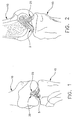
- Figs. 1 and 2 show a natural ACL 5 extending between the bottom end of a femur 10 and the top end of a tibia 15, with the body of ACL 5 passing through the femur's intercondylar notch 20.
- a natural PCL 25 extending between the bottom end of femur 10 and the top end of tibia 15.
- Fig. 3 which shows ACL 5 moving across a 10° arc as the I:nee joint is flexed through a 140° motion.
- a damaged ACL is to be replaced by a graft ACL
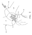
- the damaged ACL is first cleared away and then bone tunnels 30 and 35 are formed in the tibia and femur, respectively. The precise locations of these bone tunnels 30 and 35 are dictated by the isometric relationships of the knee.
- bone tunnels 30 and 35 are formed using a surgical drill guide which is keyed to certain parts of the patient's anatomy, e.g., to the patient's tibial plateau.
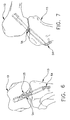
- the graft ACL may be installed in ways well known in the art. See, for example, Figs. 6 and 7, which show a graft ACL 5A having one end mounted to femur 10 and the other end mounted to tibia 15.
- proper isometric placement of bone tunnels 30 and 35 may cause anatomical conflicts within the knee when the graft ACL is installed in the patient.
- proper isometric placement of bone tunnels 30 and 35 may result in portions of the femur impinging upon the graft ACL as the knee is moved through its full range of natural motions. See, for example, Fig. 8, which shows one of the femur's condyles 40 impinging upon a graft ACL 5A extending through the femur's intercondylar notch 20; and Fig. 9, which shows the roof the femur's intercondylar notch impinging on the graft ACL 5A in the vicinity of arrow 12.
- Impingement can occur for a variety of reasons. For one thing, the intercondylar notch of many patients (particularly those who are susceptible to rupture of the ACL) is frequently small to begin with. For another thing, the graft ACL (i.e., the synthetic or harvested graft ligament which is being installed in place of the damaged natural ACL) is generally fairly large.
- the surgeon when performing an ACL reconstruction procedure, the surgeon generally tries to ensure that there is sufficient room within the patient's intercondylar notch to receive the graft ligament. This is generally done by performing notchplasty, i.e., by surgically removing any impinging bone from the sides and/or roof of the intercondylar notch. At the same time, of course, it is also important that the surgeon remove no more bone than is absolutely necessary, so as to minimize trauma to the patient.
- the surgeon typically performs the ACL reconstruction procedure in a relatively static context, i.e., with the knee being relatively stationary at any given moment during the reconstruction procedure.
- the knee must perform (and impingement must be avoided) in a relatively dynamic context, i.e., as the knee is moved throughout a full range of natural motions. This complicates the surgeon's task of eliminating impingement.
- US-A-5 383 884 describes a surgical instrument including a substantially rigid cannula shaft terminating in a cutting window at the distal end of the cannula shaft.
- the proximal end of the cannula shaft is supported by a handle having an axial bore extending therethrough.
- a flexible drive shaft connected at one end to an external drive mechanism, extends through the handle an the cannula shaft.
- a cutting head is mounted on the distal end of the drive and positioned for cooperative cutting action with the cutting window of the cannula shaft.
- a nonrotating idler shaft is journaled about the drive shaft. Severed tissue is removed or evacuated from the surgical site through an annular passage formed by the cannula and idler shafts.
- WO-A-9 612 453 describes a surgical tool of a surgical instrument which is configured to have a plurality of tissue-cutting edges circumferentially spaced by flutes disposed on an exterior surface of the tool.
- Each flute includes an aperture that intersects an interior chamber of the tool for conveying tissue fragments cut by the edges into the chamber.
- the chamber communicates with an interior passage of a rotating tube on which the tool is mounted. During operation, the tissue fragments cut by the rotating surgical tool are conveyed into the flutes and through the apertures into the chamber for removal from the surgical site through the interior passage of the tube, while the instrument remains in situ for further cutting.
- one object of the present invention is to provide improved apparatus for reconstructing a ligament.
- Another object of the present invention is to provide improved apparatus for reconstructing an anterior cruciate ligament (ACL).
- ACL anterior cruciate ligament
- Another object of the present invention is to provide improved: apparatus for quickly, easily and reliably eliminating impingement problems when reconstructing an anterior cruciate ligament.
- Still another object of the present invention is to provide improved apparatus for quickly, easily and reliably removing any anatomical structures (e.g., bone) which will conflict with the location of a graft ACL at the completion of an ACL reconstruction procedure.
- anatomical structures e.g., bone
- Yet another object of the present invention is to provide improved apparatus for quickly, easily and reliably removing any anatomical structures (e.g., bone) which will conflict with the location of a graft ACL as the knee is moved through a full range of natural motions.
- anatomical structures e.g., bone
- Yet another object of the present invention is to provide an improved method for quickly, easily and reliably removing any anatomical structures (e.g., bone) which will conflict with the location of a graft ACL as the knee is moved through a full range of natural motions.
- any anatomical structures e.g., bone
- the novel apparatus comprises a guidewire and a router assembly.
- the guidewire is similar to other guidewires of the sort well known in the art, except that it is preferably formed out of a pseudoelastic material, i.e., a "shape memory alloy (SMA)/stress induced martensite (SIM)" material such as Nitinol.
- a pseudoelastic material i.e., a "shape memory alloy (SMA)/stress induced martensite (SIM)" material such as Nitinol.
- SMA shape memory alloy
- SIM stress induced martensite
- the router assembly comprises a cannulated router device and a shield assembly.
- the cannulated router device comprises a cannulated cutting head which is attached to a cannulated shaft.
- the shield assembly comprises a body and a hood.
- the body includes a hole therein.
- the hood extends about one end of the body.
- the router assembly is assembled so that the router device has its cutting head disposed at one end of the shield assembly's body and the router device has its shaft extending through the hole in the shield assembly's body.
- the shield assembly's hood covers a first portion of the router device's cutting head while leaving a second portion of the cutting head exposed.
- the guidewire is deployed in the body so that it extends along the length where the graft ACL will reside.
- the router assembly is mounted on the guidewire by passing the guidewire through the router device's shaft and cutting head, such that the router assembly is movable along the guidewire.
- the router device's shaft is rotatable in the shield assembly such that the cutting head can be turned so as to remove bone while the router assembly is riding on the guidewire.
- Portions of the router assembly engaging the guidewire are formed so as to be flexible.
- the router assembly can be used to remove impinging bone as the knee is flexed through a full range of natural motions.
- the alternative apparatus comprising a guidewire and a cannulated router device.
- the guidewire is preferably formed out of a pseudoelastic material.
- the cannulated router device comprises a cannulated cutting head which is attached to a cannulated shalt.
- the cutting head is devoid of cutting means on a first portion of the periphery thereof and is provided with cutting means on a second portion of the periphery thereof. The second portion of the cutting head is engageable with the impinging bone portions which are to be removed.
- the guidewire is deployed in the body so that it extends along the length where the graft ACL will reside.
- the router device is mounted on the guidewire by passing the guidewire through the router device's shaft and cutting head, such that the router device is movable on the guidewire.
- the router device is rotatably movable in an oscillating fashion such that the cutting head's second portion moves in alternating opposite directions across the impinging bone to remove portions thereof.
- the first portion of the cutting head is smooth and non-destructive with respect to any anatomical structures which the first portion may come into contact with.
- Portions of the router device engaging the guidewire are formed so as to be flexible. On account of the fact that both the guidewire and portions of the router device are formed so as to be flexible, the router device can be used to remove impinging bone as the knee is flexed through a full range of natural motions.
- the alternative apparatus comprising a guidewire and a cannulated router device.
- the guidewire is preferably formed out of a pseudoelastic material.
- the cannulated router device comprises a cannulated cutting head which is attached to a cannulated shaft.
- the cutting head is adapted to cut bone which comes into contact with the cutting head, but to leave unharmed soft tissue which comes into contact with the cutting head.
- the guidewire is deployed in the body so that it extends along the length where the ACL graft will reside.
- the router device is mounted on the guidewire by passing the guidewire through the router device's shaft and cutting head, such that the router device is movable on the guidewire.
- the router device is rotatably movable on the guidewire so as to cut away impinging bone.
- portions of the router device engaging the guidewire are formed so as to be flexible.
- the router device can be used to remove impinging bone as the knee is flexed through a full range of natural motions.
- apparatus for marking portions of impinging bone which are to be thereafter removed, the apparatus comprising a guidewire and a cannulated marking device.
- the guidewire is preferably formed out of a pseudoelastic material.
- the cannulated marking device comprises a cannulated marker head attached to a cannulated shaft.
- the guidewire is deployed in the body so that it extends along the length where the graft ACL will reside.
- the marking device is mounted on the guidewire by passing the guidewire through the marking device's shaft and marking head, such that the marking head is movable on the guidewire.
- the marking head is adapted to hold a dye and to release that dye upon contact with bone, whereby to mark the impinging portions of the bone proximate to the guidewire as the marking head moves on the guidewire.
- Portions of the marking device engaging the guidewire are formed so as to be flexible.
- the marking device can be used to mark impinging bone as the knee is flexed through a full range of natural motions.
- the present invention provides apparatus for removing bone structures from the femoral notch so as to prevent those bone structures from impinging upon a graft ACL installed as part of an ACL reconstruction procedure.
- the apparatus of the present invention are intended to be utilized in an ACL reconstruction procedure after the damaged ACL has been removed from the knee and after bone tunnel 30 has been formed in tibia 15, but before bone tunnel 35 has been formed in femur 10 and the graft ACL has been positioned in the joint.
- the apparatus of the present invention comprises a guidewire 50 (Figs. 10 and 11) and a router assembly 55 (Figs. 11-16).
- Guidewire 50 is generally of the sort well known in the art for guiding cannulated elements to a target structure.
- guidewire 50 includes a sharp point GO (Fig. 10) on its distal end, whereby the guidewire can be drilled or tapped into a target structure (e.g., femur 10, as will hereinafter be described in further detail).
- a target structure e.g., femur 10
- guidewire 50 is preferably formed out of a highly elastic yet firm material.
- guidewire 50 is formed out of a so-called pseudoelastic material, i.e., a "shape memory alloy (SMA)/stress induced martensite (SIM)" material such as Nitinol. 13y forming guidewire 50 out of such a highly elastic yet firm material, the guidewire has the rigidity needed to penetrate into bone, yet has the high elasticity needed to undergo substantial clastic deformation during joint flexure, as will hereinafter be described in further detail.
- SMA shape memory alloy
- SIM stress induced martensite
- router assembly 55 comprises a cannulated router device 65 (Figs. 11-13 and 16) which comprises a cannulated cutting head 67 attached to a cannulated shaft 70.
- a cannulated router device 65 (Figs. 11-13 and 16) which comprises a cannulated cutting head 67 attached to a cannulated shaft 70.
- At least the distal portion 70' (Figs. 12, 13 and 16) of cannulated shaft 70 is flexible; the proximal portion 70" of cannulated shaft 70 may or may not be flexible, as desired.
- cannulated router device 65 can ride on guidewire 50 as rotary cutting motion is imparted to cutting head 67 by means of shaft 70.
- router device 65 can ride on guidewire 50 and rotate even as guidewire 50 is subjected to substantial bending during knee joint flexure, as will hereinafter be discussed in further detail.
- Router assembly 55 also comprises a shield assembly 75 (Figs. 11 and 14-16).
- Shield assembly 75 comprises a body assembly 00 and a hood 05.
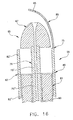
- Body assembly 00 comprises a hollow outer tube 02 (Figs. 14 and 16) and an inner collar 03 (Figs. 15 and 16). At least the distal portion 02' (Figs. 14 and 16) of hollow outer tube 02 is flexible; the proximal portion 02" of hollow outer tube 82 may or may not be flexible, as desired. Collar 03 is sized and positioned so as to terminate at the juncture of the hollow tube's distal portion 82' and its proximal portion 82" (Fig. 16). Collar 03 includes a hole 90 (Figs. 15 and 16) for receiving shaft 70 of router device 65. Hole 90 is preferably centered within body 80, whereby the router device's cutting head 67 will be centered within shield assembly 75.
- Hood 85 is attached to body 00 and includes a hole 95 (Figs. 14 and 16) for receiving guidewire 50.
- Hood 05 surrounds a portion of the router device's cutting head G7 but leaves another portion of the cutting head (i.e., the portion extending outboard of hood 85) exposed for routing operations.
- hood 05 might cover approximately 2/3 of the circumferential region surrounding cutting head 67 and leave approximately 1/3 of the circumferential region surrounding cutting head 67 exposed for cutting purposes.
- Shield 85 may be formed flexible or rigid, as desired.
- router assembly 55 can ride on guidewire 50 as a unit, with shaft 70 rotating cutting head 67 so as to cut away any material (e.g., impinging bone) exposed to the cutting head, even as hood 85 shields a substantial portion of the cutting head from inadvertently cutting other material (e.g., the patient's PCL).
- hood 85 shields a substantial portion of the cutting head from inadvertently cutting other material (e.g., the patient's PCL).
- router assembly 55 is able to ride on guidewire 50 even as guidewire 50 is subjected to substantial deformation during knee joint flexure.
- guidewire 50 and router assembly 55 are intended to be used as follows.
- femur 10 and tibia 15 are set at approximately a 90° angle and tibial bone tunnel 30 is formed in tibia 15.
- guidewire 50 is passed through tibial bone tunnel 30 and into femur 10 until the sharp distal end 60 of the guidewire is embedded in the femur, e.g., by drilling or tapping in ways well known in the art (see Figs. 17 and 18).
- a cannulated guide of the sort well known in the art may be disposed about guidewire 50 to help stabilize it as it is embedded into femur 10.
- Guidewire 50 is positioned in the patient so that it will extend along the length where the graft ACL will reside.
- router assembly 55 is loaded onto the proximal end of guidewire 50 and moved down into the interior of the knee joint so that the router assembly's cutting head 67 is in the vicinity of femoral notch 20 (see Figs. 19 and 20). Then body 80 of router assembly 55 is turned so that the router assembly's cutting head 67 is directed toward the impinging portions of the femur which are to be removed, and so that the router assembly's protective hood 05 is placed between the cutting head and the PCL so as to protect the PCL from the cutting head. Then shaft 70 is rotated, e.g., with a power driver (not shown) of the sort well known in the art, so as to rotate cutting head 67 and thereby cut away any anatomical structures it comes into contact with.
- a power driver not shown
- cutting head 67 can be used to enlarge femoral notch 20 while keeping the cutting head from engaging (and thereby cutting) the PCL and/or other sensitive anatomical structures.
- lateral notch structures can be removed.
- roof notch structures can be removed.
- the impinging bone can be removed quickly, easily and safely, without direct visualization of the anatomical structures being trimmed away, due to the use of guidewire 50 and the guidewire-following router assembly 55.
- guidewire 50 is preferably formed out of a highly elastic material, and since the router assembly's shaft portion 70' and body portion 02' are formed so as to be flexible, it is possible to use router assembly 55 to remove impinging bone in a dynamic sense, i.e., to use the router assembly to cut away impinging bone even as the knee is flexed through a full range of natural motions. See, for example, Figs. 19 and 20, where router assembly 55 is shown enlarging the femoral notch while the patient's leg is bent at approximately a 90° angle; Figs. 21 and 22, where router assembly 55 is shown enlarging the femoral notch while the patient's knee is substantially straight; and Fig.
- router assembly 55 is shown enlarging the femoral notch while the patient's knee is bent at approximately a 140° angle. It should be noted in Figs. 21 and 22, and again in Fig. 23, how guidewire 50 and router assembly 55 are capable of undergoing substantial elastic deformation during such knee flexing even as bone-trimming operations are under way.
- the apparatus of the present invention comprises guidewire 50 and a router assembly 55A.
- Router assembly 55A is substantially the same as router assembly 55 described above, except as is shown in the drawings and/or hereinafter described.
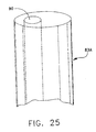
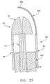
- router assembly 55A utilizes a collar 83A (Figs. 25 and 26) rather than the collar 83 described above.
- Collar 83A has its hole 90 disposed off-center within the collar, whereby the router device's cutting head 67 will be clocked to one side relative to the body's hollow outer tube 02 (see Fig. 26).
- collar 83A is arranged so that the router device's cutting head 67 is clocked outboard relative to the central axis of hollow outer tube 82. This permits the router device to engage impinging bone more readily.
- the router assembly's shield 85A has its hole 95A shifted laterally as well, in the manner shown in Fig. 26.
- router assembly 55A is intended to be used in substantially the same way is router assembly 55.
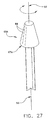
- the apparatus of the present invention comprises guidewire 50 and a cannulated router device 65A.
- Router device 65A is generally similar to the router device 65 discussed above, except that with router device 65A, its cutting teeth 09 are disposed about only a portion of the periphery of its cutting head 67A, with the remainder of the cutting head being smooth and non-abrasive.
- cannulated router device 65A on guidewire 50 so as to oscillate the router device through only a fraction of a complete revolution, bone can be removed adjacent to the cutting teeth 89 while the remainder (i.e., the non-cutting portion) of the cutting head 67A safely opposes any delicate structures which are to be safeguarded (e.g., the PCL).
- impinging bone may be safely removed without providing a shield assembly (e.g., such as the shield assembly 75 described above) for the router device.
- the cannulated router device 65A of Fig. 27 could be replaced with a cannulated router device of the sort adapted to remove hard bone while leaving soft tissue unharmed.
- the cannulated router device 65A of Fig. 27 might be replaced by the cannulated router device 65B shown in Fig. 20.
- router device 65B includes a cutting head 67B having an outer configuration similar to that disclosed in U.S. Patent No. 4,445,509 issued May 1, 1981 to David C. Auth for METHOD AND APPARATUS FOR REMOVAL OF ENCLOSED ABNORMAL DEPOSITS, which patent is hereby specifically incorporated herein by reference.
- cutting head 67B could have some other configuration of the sort well known in the art which permits cutting of hard bone without harming soft tissue.
- a cannulated router device 65B having such a configuration could then be safely rotated completely about guidewire 50 so as to remove impinging bone without risking damage to delicate soft tissue.
- impinging bone can be safely removed without providing a shield assembly (such as the shield assembly 75 described above) for the router device.
- the foregoing apparatus may be used in an ACL reconstruction procedure as follows. First, the patient's knee is extended at an angle of approximately 90°. Then, a bone tunnel 30 is formed in the tibia in ways well known in the art. Next, guidewire 50 is passed through bone tunnel 30 and up into the femur. Then a cannulated router device (in the form of either router assembly 55, or router assembly 55A, or router device 65A, or router device 65B) is loaded onto guidewire 50 and used to perform the desired notchplasty in the manner previously described. Next, the cannulated router device is dismounted from guidewire 50. Then bone tunnel 35 is formed in femur 10 in ways well known in the art. Then guidewire 50 is removed from femur 10. Finally, a graft ACL 5A is installed in femoral bone tunnel 35 and tibial bone tunnel 30 in ways well known in the art.
- the apparatus of the present invention comprises guidewire 50 and a marking device 100.
- Marking device 100 preferably comprises a resilient cannulated head 105 and a flexible cannulated shaft 110 connected to head 105.
- Cannulated head 105 is formed so that it can hold and release a dye without cutting bone.
- Marking device 100 is used by moving the device up and down guidewire 50, with or without rotation, whereby the marking head 105 will contact any bone in its way.
- marking device 100 By sizing marking device 100 properly relative to the size of the graft ACL which is to be installed, movement of marking device 100 along guidewire 50 while the knee is moved through a range of natural motions will cause the marking element to leave its dye on any portions of the femur which might impinge upon the graft ACL which will thereafter be installed in the knee. Thereafter, marking device 100 and guidewire 50 are removed from the surgical site and the surgeon may utilize a conventional cutting element to remove the marked bone. Then the graft ACL may be installed in the knee without fear of impingement.
- guidewire 50 is preferably formed out of a pseudoelastic material so as to provide the desired characteristics of firmness and flexibility.
- a guidewire made out of a non-pseudoelastic material can also be utilized in connection with the present invention.
- limitations in wire flexibility can inhibit the range of knee movements performed with the guidewire in place.
- the distal end of the guidewire in a fixture by means of a universal joint.
- This fixture can then be attached to the bottom surface of the femur or, more advantageously, it can be disposed in a bore formed in the bottom of the femur.
- this bore is the femoral bone tunnel 35 used for the ACL reconstruction procedure.
- the distal end of a non-pseudoelastic guidewire 50A can be mounted in a fixture 115 by a universal joint 120 whereby the proximal end of the guidewire can move about relative to fixture 115.
- universal joint 120 will help guidewire 50A to accommodate the degree of deformation required as the knee is moved through a full range of natural motions.
- the femoral bone tunnel 35 must be formed before the notchplasty procedure is performed, since fixture 115 is intended to be received in bone tunnel 35.
- the present invention has been described in the context of reconstructing an ACL, it should also be appreciated that the present invention has application to the reconstruction of other ligaments as well, where similar impingement problems can occur.
- the present invention might be used in connection with reconstructing the posterior cruciate ligament (PCL).
- the present invention can also be used to clear away impinging structures in other anatomical and non-anatomical settings.
- the present invention provides improved apparatus for reconstructing a ligament.
- the present invention provides improved apparatus for reconstructing an anterior cruciate ligament (ACL).
- ACL anterior cruciate ligament
- the present invention provides improved apparatus for quickly, easily and reliably eliminating impingement problems when reconstructing an anterior cruciate ligament.
- the present invention provides improved apparatus for quickly, easily and reliably removing any anatomical structures (e.g., bone) which will conflict with the location of a graft ACL at the completion of an ACI, reconstruction procedure.
- anatomical structures e.g., bone
- the present invention also provides improved apparatus for quickly, easily and reliably removing any anatomical structures (e.g., bone) which will conflict with the location of a graft ACL as the knee is moved through a full range of natural motions.
- anatomical structures e.g., bone
Landscapes
- Health & Medical Sciences (AREA)
- Surgery (AREA)
- Life Sciences & Earth Sciences (AREA)
- Orthopedic Medicine & Surgery (AREA)
- Heart & Thoracic Surgery (AREA)
- Medical Informatics (AREA)
- Oral & Maxillofacial Surgery (AREA)
- Dentistry (AREA)
- Engineering & Computer Science (AREA)
- Biomedical Technology (AREA)
- Veterinary Medicine (AREA)
- Nuclear Medicine, Radiotherapy & Molecular Imaging (AREA)
- Molecular Biology (AREA)
- Animal Behavior & Ethology (AREA)
- General Health & Medical Sciences (AREA)
- Public Health (AREA)
- Rheumatology (AREA)
- Surgical Instruments (AREA)
- Prostheses (AREA)
- Apparatus For Radiation Diagnosis (AREA)
Claims (13)
- Apparatur zum Entfernen von Teilen eines Knochens, wobei die Apparatur Folgendes aufweist:eine Fräsvorrichtung (55; 55A), die Folgendes aufweist, nämlicheinen Schaft (70);einen Fräskopf (67; 67A; 67B), der fest an den Schaft (70) angebracht ist; undeine einen Körperabschnitt aufweisende Abschirmvorrichtung (75), die ein äußeres Rohr (82) und einen Haubenabschnitt aufweist, wobei der Körperabschnitt eine durch diesen hindurchreichende Öffnung (90) zur Aufnahme des Schaftes (70) aufweist, wobei der Haubenabschnitt sich von einem Ende des Körperabschnittes weg erstreckt und eine Konkavität umgrenzt, in der teilweise der Fräskopf (67; 67A; 67B) aufnehmbar ist, dadurch gekennzeichnet, dass zumindest der distale Abschnitt (82') des hohlen äußeren Rohres (82) des Körperabschnittes und zumindest der distale Endabschnitt (70') des Schaftes (70) flexibel sind.
- Apparatur nach Anspruch 1, dadurch gekennzeichnet, dass der Fräskopf (67; 67A; 67B) und der Schaft (70) mit untereinander in Ausrichtung stehenden Bohrungen versehen sind, und die dazu vorgesehen sind, darin einen Führungsdraht (50) aufzunehmen.
- Apparatur nach Anspruch 2, dadurch gekennzeichnet, dass der Haubenabschnitt mit einer Öffnung versehen ist, die mit der Bohrung im Fräskopf ausrichtbar ist und die dazu vorgesehen ist, um den Führungsdraht (50) aufzunehmen.
- Apparatur nach Anspruch 3, dadurch gekennzeichnet, dass der Körperabschnitt zylindrisch ausgeformt ist und dass die Öffnung im Körperabschnitt sich in Längsrichtung des zylindrisch geformten Körperabschnittes erstreckt und in einer mittigen Achse des Körperabschnittes ausgespart ist.
- Apparatur nach Anspruch 4, dadurch gekennzeichnet, dass der Haubenabschnitt einen ersten Abschnitt des Fräskopfes (67; 67A; 67B) umschließt, und dass sich ein zweiter Abschnitt des Fräskopfes (67; 67A; 67B) außerhalb des Haubenabschnittes erstreckt.
- Apparatur nach Anspruch 5, dadurch gekennzeichnet, dass ein Teil des Randes des zweiten Abschnittes des Fräskopfes (67; 67A; 67B) im Wesentlichen mit einem Teil des Randes des Körperabschnittes in Ausrichtung steht.
- Apparatur nach Anspruch 5, dadurch gekennzeichnet, dass der erste Abschnitt des Fräskopfes (67; 67A; 67B) eine Mehrheit des Umfanges des Fräskopfes (67; 67A; 67B) beinhaltet.
- Apparatur nach Anspruch 3, dadurch gekennzeichnet, dass die Apparatur ferner Folgendes aufweist:einen Führungsdraht (50), wobei sich der Führungsdraht (50) durch den Schaft, durch den Fräskopf (67; 67A; 67B) und die Öffnung im Haubenabschnitt erstreckt, wobei der Schaft, der Fräskopf (67; 67A; 67B) und die Abschirmvorrichtung längs des Führungsdrahtes (50) dazu bewegbar sind, um die Fräsvorrichtung (55; 55A) längs des Führungsdrahtes vorzuschieben.
- Apparatur nach Anspruch 5, dadurch gekennzeichnet, dass der Körperabschnitt der Abschirmvorrichtung einen Kragen (83; 83A) in einer Hülse aufweist, wobei die Öffnung des Körperabschnittes sich durch den Kragen (83; 83A) hindurch erstreckt.
- Apparatur nach Anspruch 1, dadurch gekennzeichnet, dass zumindest ein Abschnitt der Abschirmvorrichtung (75) flexibel ist.
- Apparatur nach Anspruch 1, dadurch gekennzeichnet, dass die Apparatur ferner Folgendes aufweist,einen Führungsdraht (50), wobei der Führungsdraht aus einem pseudoelastischen Material gebildet ist.
- Apparatur nach Anspruch 1, ferner gekennzeichnet durch:einen Führungsdraht (50), wobei der Fräskopf (67; 67A; 67B) drehbar in der Öffnung und in dem Haubenabschnitt des Körperabschnittes angeordnet ist, der den ersten Abschnitt des Fräskopfes (67; 67A; 67B) bedeckt, wohingegen ein zweiter Abschnitt des Fräskopfes (67; 67A; 67B) freiliegend bleibt;wobei der Führungsdraht durch eine Bohrung in dem Schaft (70), eine Bohrung im Fräskopf (67; 67A; 67B) und eine Öffnung in dem Haubenabschnitt der Abschirmvorrichtung sich erstreckt, wodurch die Fräsvorrichtung (55; 55A) längs des Führungsdrahtes (50) beweglich ist, und wobei der Schaft (70) in dem Körperabschnitt der Haubenvorrichtung drehbar ist, so dass der zweite Abschnitt des Fräskopfes (67; 67A; 67B) mit einem Knochen in Eingriff treten kann und zum Entfernen von Teilen des Knochens betätigbar ist.
- Apparatur nach Anspruch 1, gekennzeichnet durch einen Führungsdraht (50), der durch eine im Schaft (70) sich erstreckende Bohrung hindurcherstreckbar ist, wobei der Fräskopf (67; 67A; 67B) in einem ersten Abschnitt seines Umfanges keine Fräsmittel aufweist, und der in einem zweiten Abschnitt seines Umfanges Fräsmittel aufweist, wobei der zweite Abschnitt des Fräskopfes (67; 67A; 67B) mit den zu entfernenden Knochenbereichen in Eingriff bringbar ist, wobei der Schaft (70) und der Fräskopf (67; 67A; 67B) in einer oszillierenden Art und Weise derart drehbewegbar sind, dass sich der zweite Abschnitt des Fräskopfes in alternierend entgegengesetzten Richtungen über die zu entfernenden Bereiche des Knochens bewegt, wobei der erste Abschnitt glatt und nicht abtragend bezüglich der anatomischen Strukturen ist, mit denen der erste Abschnitt in Kontakt tritt, und wobei zumindest der distale Abschnitt des Körperabschnittes, des Führungsdrahtes und des Schaftes flexibel sind.
Applications Claiming Priority (3)
| Application Number | Priority Date | Filing Date | Title |
|---|---|---|---|
| US08/658,003 US5755718A (en) | 1996-06-04 | 1996-06-04 | Apparatus and method for reconstructing ligaments |
| US658003 | 1996-06-04 | ||
| PCT/US1997/009431 WO1997046162A1 (en) | 1996-06-04 | 1997-06-03 | Apparatus and method for reconstructing ligaments |
Publications (3)
| Publication Number | Publication Date |
|---|---|
| EP0910291A1 EP0910291A1 (de) | 1999-04-28 |
| EP0910291A4 EP0910291A4 (de) | 2004-12-22 |
| EP0910291B1 true EP0910291B1 (de) | 2007-07-25 |
Family
ID=24639512
Family Applications (1)
| Application Number | Title | Priority Date | Filing Date |
|---|---|---|---|
| EP97926859A Expired - Lifetime EP0910291B1 (de) | 1996-06-04 | 1997-06-03 | Vorrichtung zur rekonstruktion von sehnen |
Country Status (7)
| Country | Link |
|---|---|
| US (5) | US5755718A (de) |
| EP (1) | EP0910291B1 (de) |
| JP (1) | JP2000512171A (de) |
| AU (1) | AU739665B2 (de) |
| CA (1) | CA2257398C (de) |
| DE (1) | DE69737948T2 (de) |
| WO (1) | WO1997046162A1 (de) |
Families Citing this family (74)
| Publication number | Priority date | Publication date | Assignee | Title |
|---|---|---|---|---|
| US5755718A (en) * | 1996-06-04 | 1998-05-26 | Sklar; Joseph H. | Apparatus and method for reconstructing ligaments |
| US5954716A (en) | 1997-02-19 | 1999-09-21 | Oratec Interventions, Inc | Method for modifying the length of a ligament |
| US6280472B1 (en) * | 1997-07-23 | 2001-08-28 | Arthrotek, Inc. | Apparatus and method for tibial fixation of soft tissue |
| US6149654A (en) * | 1998-05-21 | 2000-11-21 | Johnson; Lanny L. | Intra-articular drill |
| US6214009B1 (en) * | 1998-09-09 | 2001-04-10 | Xomed Surgical Products, Inc. | Rhinoplasty bur |
| US6280447B1 (en) * | 1998-12-23 | 2001-08-28 | Nuvasive, Inc. | Bony tissue resector |
| US6579298B1 (en) * | 2000-02-29 | 2003-06-17 | Scimed Life Systems, Inc. | Method and apparatus for treating vein graft lesions |
| US6325804B1 (en) * | 2000-06-28 | 2001-12-04 | Ethicon, Inc. | Method for fixing a graft in a bone tunnel |
| US20040153153A1 (en) * | 2001-05-31 | 2004-08-05 | Elson Robert J. | Anterior cruciate ligament reconstruction system and method of implementing same |
| US20050065533A1 (en) * | 2001-05-31 | 2005-03-24 | Magen Hugh E. | Apparatus for assembling anterior cruciate ligament reconstruction system |
| USD549344S1 (en) * | 2003-01-16 | 2007-08-21 | Concept Matrix, Llc | Diskectomy tool with convex head |
| US8070750B2 (en) * | 2004-03-05 | 2011-12-06 | Depuy Mitek, Inc. | Tunnel notcher and guidewire delivery device |
| US7857813B2 (en) | 2006-08-29 | 2010-12-28 | Baxano, Inc. | Tissue access guidewire system and method |
| US8062300B2 (en) | 2006-05-04 | 2011-11-22 | Baxano, Inc. | Tissue removal with at least partially flexible devices |
| US7738969B2 (en) | 2004-10-15 | 2010-06-15 | Baxano, Inc. | Devices and methods for selective surgical removal of tissue |
| US8048080B2 (en) | 2004-10-15 | 2011-11-01 | Baxano, Inc. | Flexible tissue rasp |
| US8221397B2 (en) | 2004-10-15 | 2012-07-17 | Baxano, Inc. | Devices and methods for tissue modification |
| US8430881B2 (en) | 2004-10-15 | 2013-04-30 | Baxano, Inc. | Mechanical tissue modification devices and methods |
| US7578819B2 (en) | 2005-05-16 | 2009-08-25 | Baxano, Inc. | Spinal access and neural localization |
| US7738968B2 (en) | 2004-10-15 | 2010-06-15 | Baxano, Inc. | Devices and methods for selective surgical removal of tissue |
| US8617163B2 (en) | 2004-10-15 | 2013-12-31 | Baxano Surgical, Inc. | Methods, systems and devices for carpal tunnel release |
| US7887538B2 (en) | 2005-10-15 | 2011-02-15 | Baxano, Inc. | Methods and apparatus for tissue modification |
| AU2005295589B2 (en) | 2004-10-15 | 2009-12-03 | Baxano, Inc. | Devices and methods for tissue removal |
| US8257356B2 (en) | 2004-10-15 | 2012-09-04 | Baxano, Inc. | Guidewire exchange systems to treat spinal stenosis |
| US20110190772A1 (en) | 2004-10-15 | 2011-08-04 | Vahid Saadat | Powered tissue modification devices and methods |
| US7938830B2 (en) | 2004-10-15 | 2011-05-10 | Baxano, Inc. | Powered tissue modification devices and methods |
| US7959577B2 (en) | 2007-09-06 | 2011-06-14 | Baxano, Inc. | Method, system, and apparatus for neural localization |
| US9101386B2 (en) | 2004-10-15 | 2015-08-11 | Amendia, Inc. | Devices and methods for treating tissue |
| US20100331883A1 (en) | 2004-10-15 | 2010-12-30 | Schmitz Gregory P | Access and tissue modification systems and methods |
| US9247952B2 (en) | 2004-10-15 | 2016-02-02 | Amendia, Inc. | Devices and methods for tissue access |
| US20060142775A1 (en) * | 2004-12-29 | 2006-06-29 | Depuy Mitek, Inc. | Surgical tool with cannulated rotary tip |
| US8366712B2 (en) | 2005-10-15 | 2013-02-05 | Baxano, Inc. | Multiple pathways for spinal nerve root decompression from a single access point |
| US8062298B2 (en) | 2005-10-15 | 2011-11-22 | Baxano, Inc. | Flexible tissue removal devices and methods |
| US8092456B2 (en) | 2005-10-15 | 2012-01-10 | Baxano, Inc. | Multiple pathways for spinal nerve root decompression from a single access point |
| US7371260B2 (en) * | 2005-10-26 | 2008-05-13 | Biomet Sports Medicine, Inc. | Method and instrumentation for the preparation and transplantation of osteochondral allografts |
| US7837717B2 (en) | 2006-03-24 | 2010-11-23 | Depuy Products, Inc. | Fastening system for internal fixation |
| US8109958B1 (en) * | 2006-06-01 | 2012-02-07 | Neville Alleyne | Method and apparatus for spinal osteoligamentous resection |
| US7749226B2 (en) * | 2006-09-22 | 2010-07-06 | Biomet Sports Medicine, Llc | Method for forming a tunnel in a bone |
| GB2443795B (en) * | 2006-10-06 | 2011-04-13 | Dalmatic As | Leads for use in orthopaedic surgery |
| US7942914B2 (en) * | 2006-10-17 | 2011-05-17 | Arthroscopic Innovations Llc | Method and apparatus for surgical repair |
| US8303592B2 (en) * | 2007-10-05 | 2012-11-06 | Biomet Manufacturing Corp. | System for forming a tendon-bone graft |
| US8322256B2 (en) * | 2007-10-05 | 2012-12-04 | Biomet Manufacturing Corp. | System for forming a tendon-bone graft |
| US8192436B2 (en) | 2007-12-07 | 2012-06-05 | Baxano, Inc. | Tissue modification devices |
| US8771273B2 (en) * | 2007-12-17 | 2014-07-08 | Karl Storz Gmbh & Co. Kg | Surgical drill for providing holes at an angle |
| US8437938B2 (en) * | 2008-01-15 | 2013-05-07 | GM Global Technology Operations LLC | Axle torque based cruise control |
| US20090281581A1 (en) | 2008-05-06 | 2009-11-12 | Berg Jeffery H | Method and device for securing sutures to bones |
| WO2010009093A2 (en) | 2008-07-14 | 2010-01-21 | Baxano, Inc | Tissue modification devices |
| US8398641B2 (en) | 2008-07-01 | 2013-03-19 | Baxano, Inc. | Tissue modification devices and methods |
| US8409206B2 (en) | 2008-07-01 | 2013-04-02 | Baxano, Inc. | Tissue modification devices and methods |
| US9314253B2 (en) | 2008-07-01 | 2016-04-19 | Amendia, Inc. | Tissue modification devices and methods |
| CN102231968A (zh) * | 2008-10-14 | 2011-11-02 | 脊柱建筑师公司 | 重建脊柱 |
| EP2405823A4 (de) | 2009-03-13 | 2012-07-04 | Baxano Inc | Vorrichtungen und verfahren für flexible nervenortung |
| AU2010236136B2 (en) | 2009-04-17 | 2014-07-10 | Shane Barwood | Tenodesis system |
| US8491585B2 (en) * | 2009-05-06 | 2013-07-23 | Kambiz Hannani | Methods and systems for minimally invasive lateral decompression |
| US8394102B2 (en) | 2009-06-25 | 2013-03-12 | Baxano, Inc. | Surgical tools for treatment of spinal stenosis |
| US8911474B2 (en) | 2009-07-16 | 2014-12-16 | Howmedica Osteonics Corp. | Suture anchor implantation instrumentation system |
| CA2812775C (en) | 2009-08-20 | 2015-09-29 | Howmedica Osteonics Corp. | Flexible acl instrumentation, kit and method |
| JP5859009B2 (ja) * | 2010-09-23 | 2016-02-10 | アルファテック スパイン, インコーポレイテッド | クランプ棘間スペーサ装置及び使用方法 |
| CN101940490B (zh) * | 2010-09-30 | 2012-05-23 | 重庆润泽医疗器械有限公司 | 一种手术用铣刀托架 |
| US9795398B2 (en) | 2011-04-13 | 2017-10-24 | Howmedica Osteonics Corp. | Flexible ACL instrumentation, kit and method |
| US9333069B2 (en) | 2011-10-14 | 2016-05-10 | Biomet Sports Medicine, Llc | Method and apparatus for attaching soft tissue to bone |
| US9445803B2 (en) | 2011-11-23 | 2016-09-20 | Howmedica Osteonics Corp. | Filamentary suture anchor |
| US9808242B2 (en) | 2012-04-06 | 2017-11-07 | Howmedica Osteonics Corp. | Knotless filament anchor for soft tissue repair |
| US8821494B2 (en) | 2012-08-03 | 2014-09-02 | Howmedica Osteonics Corp. | Surgical instruments and methods of use |
| US9011443B2 (en) * | 2012-09-20 | 2015-04-21 | Depuy Mitek, Llc | Low profile reamers and methods of use |
| US9078740B2 (en) | 2013-01-21 | 2015-07-14 | Howmedica Osteonics Corp. | Instrumentation and method for positioning and securing a graft |
| US9402620B2 (en) | 2013-03-04 | 2016-08-02 | Howmedica Osteonics Corp. | Knotless filamentary fixation devices, assemblies and systems and methods of assembly and use |
| WO2014176270A1 (en) | 2013-04-22 | 2014-10-30 | Pivot Medical, Inc. | Method and apparatus for attaching tissue to bone |
| EP3030168B1 (de) * | 2013-08-07 | 2021-01-20 | Arthrex, Inc. | Meniskussondenschneider |
| US9986992B2 (en) | 2014-10-28 | 2018-06-05 | Stryker Corporation | Suture anchor and associated methods of use |
| DE102015208646A1 (de) * | 2015-05-08 | 2016-11-10 | Frank Zastrow | Chirurgisches Handgerät sowie eine Schutzeinrichtung |
| EP3115004B1 (de) | 2015-07-09 | 2022-11-02 | Carevature Medical Ltd. | Chirurgisches trennschleifinstrument |
| US11554197B2 (en) * | 2018-11-20 | 2023-01-17 | BioMark, LLC | Device with an open cell element |
| US20250099114A1 (en) * | 2023-09-27 | 2025-03-27 | Michael Smith | Eccentrically rotating cutting tool |
Family Cites Families (29)
| Publication number | Priority date | Publication date | Assignee | Title |
|---|---|---|---|---|
| US2429356A (en) * | 1947-01-10 | 1947-10-21 | Richard J Hicks | Surgical cutter guard |
| DE1029528B (de) * | 1954-01-30 | 1958-05-08 | Med H C Ernst Pohl Dr | Vorrichtung zum Markieren eines anzulegenden Bohrloches besonders fuer Knochennaegelund Knochenschrauben |
| US4445509A (en) * | 1982-02-04 | 1984-05-01 | Auth David C | Method and apparatus for removal of enclosed abnormal deposits |
| US4760844A (en) * | 1986-03-21 | 1988-08-02 | Ace Medical Company | Cannulated screw dye injector |
| US5195526A (en) * | 1988-03-11 | 1993-03-23 | Michelson Gary K | Spinal marker needle |
| US4909250A (en) * | 1988-11-14 | 1990-03-20 | Smith Joseph R | Implant system for animal identification |
| FR2649604B1 (fr) * | 1989-07-11 | 1995-05-19 | Laboureau Jacques Philippe | Instrument ancillaire chirurgical de reperage de l'entree et de la direction du tunnel d'insertion femorale d'un neo-ligament dans des conditions d'isometrie totale |
| JP2876415B2 (ja) * | 1990-01-30 | 1999-03-31 | 株式会社スズキエンジニアリング | 医療用ドリルと内視鏡付きドリル装置 |
| US5139520A (en) * | 1990-01-31 | 1992-08-18 | American Cyanamid Company | Method for acl reconstruction |
| US5122134A (en) * | 1990-02-02 | 1992-06-16 | Pfizer Hospital Products Group, Inc. | Surgical reamer |
| US5242460A (en) * | 1990-10-25 | 1993-09-07 | Devices For Vascular Intervention, Inc. | Atherectomy catheter having axially-disposed cutting edge |
| US5320115A (en) * | 1991-01-16 | 1994-06-14 | Applied Biological Concepts | Method and apparatus for arthroscopic knee surgery |
| US5112337A (en) * | 1991-02-05 | 1992-05-12 | Depuy Du Pont Orthopaedics | Variable angle, selective length tibial drill guide |
| US5464407A (en) * | 1991-02-19 | 1995-11-07 | Mcguire; David A. | Flexible surgical screwdriver and methods of arthroscopic ligament reconstruction |
| US5234435A (en) * | 1991-03-08 | 1993-08-10 | Seagrave Jr Richard A | Surgical method and apparatus |
| US5562669A (en) * | 1994-01-13 | 1996-10-08 | Mcguire; David A. | Cruciate ligament reconstruction with tibial drill guide |
| US5269786A (en) * | 1992-02-20 | 1993-12-14 | Arthrex Inc. | PCL oriented placement tibial guide method |
| US5437288A (en) * | 1992-09-04 | 1995-08-01 | Mayo Foundation For Medical Education And Research | Flexible catheter guidewire |
| US5360432A (en) * | 1992-10-16 | 1994-11-01 | Shturman Cardiology Systems, Inc. | Abrasive drive shaft device for directional rotational atherectomy |
| US5383884A (en) * | 1992-12-04 | 1995-01-24 | American Biomed, Inc. | Spinal disc surgical instrument |
| US5350380A (en) * | 1993-01-15 | 1994-09-27 | Depuy Inc. | Method for securing a ligament replacement in a bone |
| US5593416A (en) * | 1993-01-26 | 1997-01-14 | Donahue; John R. | Method of using flexible surgical instrument |
| US5706809A (en) * | 1993-01-29 | 1998-01-13 | Cardima, Inc. | Method and system for using multiple intravascular sensing devices to detect electrical activity |
| US5372599A (en) * | 1993-03-12 | 1994-12-13 | Mitek Surgical Products, Inc. | Surgical anchor and method for deploying the same |
| US5456689A (en) * | 1993-10-13 | 1995-10-10 | Arnold J. Kresch | Method and device for tissue resection |
| US5458602A (en) * | 1994-01-11 | 1995-10-17 | Mitek Surgical Products, Inc. | Surgical drill guide |
| AU701424B2 (en) * | 1994-10-24 | 1999-01-28 | Smith & Nephew, Inc. | Hollow surgical cutter with apertured flutes |
| US5601561A (en) * | 1995-01-17 | 1997-02-11 | W. L. Gore & Associates, Inc. | Guided bone rasp |
| US5755718A (en) * | 1996-06-04 | 1998-05-26 | Sklar; Joseph H. | Apparatus and method for reconstructing ligaments |
-
1996
- 1996-06-04 US US08/658,003 patent/US5755718A/en not_active Expired - Lifetime
-
1997
- 1997-06-03 DE DE69737948T patent/DE69737948T2/de not_active Expired - Lifetime
- 1997-06-03 EP EP97926859A patent/EP0910291B1/de not_active Expired - Lifetime
- 1997-06-03 JP JP10500738A patent/JP2000512171A/ja active Pending
- 1997-06-03 WO PCT/US1997/009431 patent/WO1997046162A1/en not_active Ceased
- 1997-06-03 AU AU31520/97A patent/AU739665B2/en not_active Ceased
- 1997-06-03 CA CA002257398A patent/CA2257398C/en not_active Expired - Fee Related
-
1998
- 1998-05-22 US US09/083,889 patent/US5941883A/en not_active Expired - Lifetime
-
1999
- 1999-08-24 US US09/379,997 patent/US6364886B1/en not_active Expired - Fee Related
-
2002
- 2002-04-02 US US10/114,659 patent/US6685709B2/en not_active Expired - Fee Related
-
2004
- 2004-02-03 US US10/770,848 patent/US20040220576A1/en not_active Abandoned
Non-Patent Citations (1)
| Title |
|---|
| None * |
Also Published As
| Publication number | Publication date |
|---|---|
| CA2257398C (en) | 2008-05-06 |
| US5941883A (en) | 1999-08-24 |
| US20020173795A1 (en) | 2002-11-21 |
| DE69737948D1 (de) | 2007-09-06 |
| US6364886B1 (en) | 2002-04-02 |
| CA2257398A1 (en) | 1997-12-11 |
| DE69737948T2 (de) | 2008-04-03 |
| AU3152097A (en) | 1998-01-05 |
| AU739665B2 (en) | 2001-10-18 |
| US5755718A (en) | 1998-05-26 |
| EP0910291A4 (de) | 2004-12-22 |
| US20040220576A1 (en) | 2004-11-04 |
| WO1997046162A1 (en) | 1997-12-11 |
| EP0910291A1 (de) | 1999-04-28 |
| JP2000512171A (ja) | 2000-09-19 |
| US6685709B2 (en) | 2004-02-03 |
Similar Documents
| Publication | Publication Date | Title |
|---|---|---|
| EP0910291B1 (de) | Vorrichtung zur rekonstruktion von sehnen | |
| WO1997046162A9 (en) | Apparatus and method for reconstructing ligaments | |
| EP2092901B1 (de) | Führungselement zur Schaffung eines femoralen Tunnels während der ACL-Rekonstruktion | |
| EP1941841B1 (de) | Tunnelkerbgerät und Leitdrahtabgabevorrichtung | |
| EP2236100B1 (de) | Mikrobruchinstrument | |
| US8323289B2 (en) | Tibial guide for ACL repair having left/right docking configuration | |
| US10390846B2 (en) | Apparatus for and method of providing a hip replacement | |
| US5624447A (en) | Surgical tool guide and entry hole positioner | |
| EP2072015B1 (de) | Chirurgischer Bohrer zur Bereitstellung von Löchern in einem Winkel | |
| EP2510886B1 (de) | Flexible Kreuzbandinstrumentierung | |
| US20090216236A1 (en) | Device for orienting the tibial tunnel position during an acl reconstruction | |
| KR20160118392A (ko) | 수술용 조준 장치 | |
| US20110034933A1 (en) | Ligament reconstruction guide assembly and methods of use | |
| JP2005046625A (ja) | 最小の侵略的な遠位大腿骨切除のための方法および装置 | |
| WO2011031518A2 (en) | Femoral guide for acl repair having reduced profile for left/right knee configurations | |
| US20250275775A1 (en) | Guidance tools, systems, and methods | |
| Windsor et al. | Exposure in revision total knee arthroplasty: the femoral peel | |
| WO2011025741A1 (en) | Tibial guide for acl repair having off-axis guide wire arrangement | |
| EP4082454B1 (de) | Schnurloses führungssystem | |
| Frumberg et al. | Retrograde Intramedullary Femur Lengthening with Fitbone™ Lengthening System: Tips and Tricks | |
| EP3435897B1 (de) | Führungs- und schutzelement für ein instrument zum abtragen von knochengewebe und ein instrument zum abtragen von knochengewebe mit einem solchen element |
Legal Events
| Date | Code | Title | Description |
|---|---|---|---|
| PUAI | Public reference made under article 153(3) epc to a published international application that has entered the european phase |
Free format text: ORIGINAL CODE: 0009012 |
|
| 17P | Request for examination filed |
Effective date: 19990104 |
|
| AK | Designated contracting states |
Kind code of ref document: A1 Designated state(s): DE FR GB IT |
|
| RIC1 | Information provided on ipc code assigned before grant |
Ipc: 7A 61B 17/32 B Ipc: 7A 61B 17/17 B Ipc: 7A 61B 17/16 A |
|
| RIC1 | Information provided on ipc code assigned before grant |
Ipc: 7A 61B 19/00 B Ipc: 7A 61B 17/32 B Ipc: 7A 61B 17/17 B Ipc: 7A 61B 17/16 A |
|
| A4 | Supplementary search report drawn up and despatched |
Effective date: 20041103 |
|
| 17Q | First examination report despatched |
Effective date: 20050126 |
|
| RTI1 | Title (correction) |
Free format text: APPARATUS FOR RECONSTRUCTING LIGAMENTS |
|
| GRAP | Despatch of communication of intention to grant a patent |
Free format text: ORIGINAL CODE: EPIDOSNIGR1 |
|
| GRAS | Grant fee paid |
Free format text: ORIGINAL CODE: EPIDOSNIGR3 |
|
| GRAA | (expected) grant |
Free format text: ORIGINAL CODE: 0009210 |
|
| AK | Designated contracting states |
Kind code of ref document: B1 Designated state(s): DE FR GB IT |
|
| REG | Reference to a national code |
Ref country code: GB Ref legal event code: FG4D |
|
| REF | Corresponds to: |
Ref document number: 69737948 Country of ref document: DE Date of ref document: 20070906 Kind code of ref document: P |
|
| ET | Fr: translation filed | ||
| PLBE | No opposition filed within time limit |
Free format text: ORIGINAL CODE: 0009261 |
|
| STAA | Information on the status of an ep patent application or granted ep patent |
Free format text: STATUS: NO OPPOSITION FILED WITHIN TIME LIMIT |
|
| 26N | No opposition filed |
Effective date: 20080428 |
|
| PGFP | Annual fee paid to national office [announced via postgrant information from national office to epo] |
Ref country code: FR Payment date: 20120705 Year of fee payment: 16 Ref country code: GB Payment date: 20120525 Year of fee payment: 16 |
|
| PGFP | Annual fee paid to national office [announced via postgrant information from national office to epo] |
Ref country code: IT Payment date: 20120526 Year of fee payment: 16 |
|
| GBPC | Gb: european patent ceased through non-payment of renewal fee |
Effective date: 20130603 |
|
| REG | Reference to a national code |
Ref country code: FR Ref legal event code: ST Effective date: 20140228 |
|
| PG25 | Lapsed in a contracting state [announced via postgrant information from national office to epo] |
Ref country code: GB Free format text: LAPSE BECAUSE OF NON-PAYMENT OF DUE FEES Effective date: 20130603 |
|
| PG25 | Lapsed in a contracting state [announced via postgrant information from national office to epo] |
Ref country code: IT Free format text: LAPSE BECAUSE OF NON-PAYMENT OF DUE FEES Effective date: 20130603 Ref country code: FR Free format text: LAPSE BECAUSE OF NON-PAYMENT OF DUE FEES Effective date: 20130701 |
|
| PGFP | Annual fee paid to national office [announced via postgrant information from national office to epo] |
Ref country code: DE Payment date: 20140523 Year of fee payment: 18 |
|
| REG | Reference to a national code |
Ref country code: DE Ref legal event code: R119 Ref document number: 69737948 Country of ref document: DE |
|
| PG25 | Lapsed in a contracting state [announced via postgrant information from national office to epo] |
Ref country code: DE Free format text: LAPSE BECAUSE OF NON-PAYMENT OF DUE FEES Effective date: 20160101 |