EP3435897B1 - Führungs- und schutzelement für ein instrument zum abtragen von knochengewebe und ein instrument zum abtragen von knochengewebe mit einem solchen element - Google Patents
Führungs- und schutzelement für ein instrument zum abtragen von knochengewebe und ein instrument zum abtragen von knochengewebe mit einem solchen element Download PDFInfo
- Publication number
- EP3435897B1 EP3435897B1 EP17718415.7A EP17718415A EP3435897B1 EP 3435897 B1 EP3435897 B1 EP 3435897B1 EP 17718415 A EP17718415 A EP 17718415A EP 3435897 B1 EP3435897 B1 EP 3435897B1
- Authority
- EP
- European Patent Office
- Prior art keywords
- guide
- protection element
- bone removal
- bone
- removal instrument
- Prior art date
- Legal status (The legal status is an assumption and is not a legal conclusion. Google has not performed a legal analysis and makes no representation as to the accuracy of the status listed.)
- Active
Links
Images


Classifications
-
- A—HUMAN NECESSITIES
- A61—MEDICAL OR VETERINARY SCIENCE; HYGIENE
- A61B—DIAGNOSIS; SURGERY; IDENTIFICATION
- A61B17/00—Surgical instruments, devices or methods
- A61B17/32—Surgical cutting instruments
- A61B17/320016—Endoscopic cutting instruments, e.g. arthroscopes, resectoscopes
- A61B17/32002—Endoscopic cutting instruments, e.g. arthroscopes, resectoscopes with continuously rotating, oscillating or reciprocating cutting instruments
-
- A—HUMAN NECESSITIES
- A61—MEDICAL OR VETERINARY SCIENCE; HYGIENE
- A61B—DIAGNOSIS; SURGERY; IDENTIFICATION
- A61B90/00—Instruments, implements or accessories specially adapted for surgery or diagnosis and not covered by any of the groups A61B1/00 - A61B50/00, e.g. for luxation treatment or for protecting wound edges
- A61B90/08—Accessories or related features not otherwise provided for
-
- A—HUMAN NECESSITIES
- A61—MEDICAL OR VETERINARY SCIENCE; HYGIENE
- A61B—DIAGNOSIS; SURGERY; IDENTIFICATION
- A61B90/00—Instruments, implements or accessories specially adapted for surgery or diagnosis and not covered by any of the groups A61B1/00 - A61B50/00, e.g. for luxation treatment or for protecting wound edges
- A61B90/08—Accessories or related features not otherwise provided for
- A61B2090/0801—Prevention of accidental cutting or pricking
- A61B2090/08021—Prevention of accidental cutting or pricking of the patient or his organs
-
- A—HUMAN NECESSITIES
- A61—MEDICAL OR VETERINARY SCIENCE; HYGIENE
- A61B—DIAGNOSIS; SURGERY; IDENTIFICATION
- A61B2217/00—General characteristics of surgical instruments
- A61B2217/002—Auxiliary appliance
- A61B2217/005—Auxiliary appliance with suction drainage system
Definitions
- the present invention relates to a guide and protection element for a bone removal instrument.
- the present invention also relates to a bone removal instrument comprising said guide and protection element.
- Both objects of the present invention are of particular use in bone surgery, in particular in arthroscopic or open surgery, where the excision of osteophytes, bony protrusions or bone scar tissue is required.
- the anatomical parts most prone to this pathology are, for example, the hip, the shoulder and the ankle, i.e., those parts of the body that are most easily injured.
- the neck of the femur is a cylindrical structure that may, at times, have pathological bone spurs which need to be removed and could lead to femoral acetabular impingement.
- Femoral acetabular impingement is caused by a series of congenital or acquired hip pathologies, the main pathogenic factor being abnormal contact between the two parts of the hip joint (the acetabulum and the proximal part of the femur).
- Acquired impingement typically occurs as a result of bony outgrowths produced through trauma: it is a condition that affects athletes in particular.
- This type of pathology can also affect other parts of the body, such as the shoulder, for example: in this case it is known as subacromial impingement.
- the pain in the shoulder is usually due to a problem at the level of the rotator cuff tendons.
- Tendons are fibrous structures that attach the muscles to the bone.
- the rotator cuff tendons are located between two bones within the shoulder. Repeated microtrauma, a single contusion or even ordinary wear over the years contribute to a thickening of the tendons which gives rise to rubbing or impingement of the two bones.
- the ankle is also prone to sprains, repeated microtrauma or fractures which can give rise to what is known as fibrous impingement.
- the osteophyte or scar tissue must be removed surgically.
- the surgical operation is performed using an arthroscopic procedure, which involves inserting the arthroscope and special instruments to excise the inflammatory or scar tissue and bony spurs.
- a small motorised instrument generally a small cutter, is inserted to cut and draw out the excess portion of tissue.
- An example of such an instrument is described in document US 5 084 052 .
- the cutter is only used under visual control, therefore the surgeon has no reference for determining the amount of bone that is removed. Incorrect assessment of the amount of bone that is removed could increase the duration of the surgical procedure or, on the contrary, entail the risk of making the remaining bone too thin.
- one purpose of the present invention is to provide a guide and protection element that allows the bone removal instrument to be used in safety.
- Another purpose of the present invention is to provide a guide and protection element for a bone removal instrument that protects the surrounding soft tissue which must not be damaged.
- a further purpose of the present invention is to provide a guide and protection element for a bone removal instrument that provides a visual reference for the surgeon during the surgical procedure.
- a purpose of the present invention is to implement a bone removal instrument which allows the surgeon to perform the operation quickly and in safety, without any risk of injury to the patient.
- the present invention discloses a guide and protection element for a bone removal instrument, the characteristic of which is set forth in Claim 1.
- a further object of the present invention is a bone removal instrument, as disclosed in one of the appended claims.
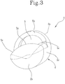
- reference numeral 1 generally indicates a guide and protection element for bone removal instruments.
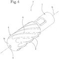
- Said guide and protection element 1 comprises a cylindrical body 2 suitable to be fitted over a bone removal instrument 3 of the type illustrated in Figure 4 .
- the cylindrical body 2 has a first end 2a that is completely open, through which the bone removal instrument 3 is inserted, and a second end 2b that is at least partially closed, upon which the instrument abuts when it is fully inserted in the guide and protection element 1.
- a pin 4 that protrudes axially from the second end 2b and projects towards the first end 2a.
- the pin 4 is aligned with a longitudinal axis 1a of the cylindrical body 2 and engages axially with the bone removal instrument 3.
- the bone removal instrument 3 rotates with respect to the guide and protection element 1, which remains stationary while the former is being operated.
- the cylindrical body 2 is provided, on one lateral surface 2c, with at least one window 5 interposed between the first end 2a and the second end 2b.
- the bone removal instrument 3 faces outwards through this window 5, at least partially, in particular a part of a cutting head 6 of the instrument, so that the cutting head 6 can operate on a bone to be treated in a controlled and guided manner.
- the cutting head 6 is no longer completely exposed: only a part of it can interact with the bone.
- the window 5 is delimited by an upper edge 5a, a lower edge 5b and two lateral edges 5c, which define abutment elements upon which the anatomical parts surrounding the part of bone to be removed rest, in addition to defining a visual reference for the surgeon.
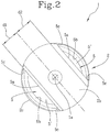
- the cylindrical body 2 is provided with at least two windows 5' and 5" on the lateral surface 2c, which are preferably arranged opposite to one another with respect to the axis 1a of the guide element 1.
- the two windows 5' and 5" differ from one another in size, in terms of their width and/or depth on the lateral surface 2c.
- each window may be of a different size to the other in terms of their overall dimensions between the first 2a and the second 2b end of the cylindrical body.
- transverse dimensions may also be different and cover a greater or lesser circular sector on the lateral surface 2c.
- the windows are also at a different depth from the lateral surface 2c towards the axis of the cylindrical body 1a.
- the plan view from above, from the second end 2b to the first end 2a, of one window 5' is different from the same plan view of the other window 5".
- the second end 2b may be asymmetrical with respect to the axis 1a of the cylindrical body 2.
- the distance d1 between the longitudinal axis 1a of the cylindrical body 2 and the upper edge 5a delimiting one window 5' is different from the corresponding distance d2 between the longitudinal axis 1a and the upper edge 5a delimiting the other window 5".
- the windows may both have the same dimensions.
- the cylindrical body 2 has a circular cross section.
- the bone removal instrument 3 is, preferably, a motorised rotary cutter.
- This instrument comprising a spindle 7 and a cylindrical cutting head 6 with circular cross section, having axially elongated blades 8 extending in a helical manner along the axial length of the cutting head 6.
- the cutting head 6 is provided with a seat 9 for inserting the pin 4 of the cylindrical body 2.
- the bone removal instrument 3 further comprises an integrated suction system for the removal of unwanted bone tissue.
- the guide and protection element 1 described above is fitted over the bone removal instrument 3 to protect the cutting head 6 and leave only a part thereof exposed. In particular, only the portion that interacts with the part of bone to be removed is exposed.
- each window 5' and 5" serve as an abutment element, beyond which the blade cannot cut.
- the window 5 thus provides the surgeon with an accurate reference of the amount of bone that must be removed, thus avoiding excessive bone removal.
- the guide and protection element 1 covers the part of blade that is not involved in the cutting, so as to protect surrounding anatomical parts, such as tendons, neurovascular structures or other soft tissue, which must not be cut.
- the guide and protection element implements a visual reference for the surgeon, facilitating the phases of the surgical procedure.
- the guide and protection element protects the area around the bone, eliminating the risk of accidental damage.
- the bone removal instrument equipped with this guide and protection element is more manageable and allows the surgeon to operate in greater safety.
Landscapes
- Health & Medical Sciences (AREA)
- Surgery (AREA)
- Life Sciences & Earth Sciences (AREA)
- Heart & Thoracic Surgery (AREA)
- Molecular Biology (AREA)
- Veterinary Medicine (AREA)
- Engineering & Computer Science (AREA)
- Biomedical Technology (AREA)
- Nuclear Medicine, Radiotherapy & Molecular Imaging (AREA)
- Medical Informatics (AREA)
- Public Health (AREA)
- Animal Behavior & Ethology (AREA)
- General Health & Medical Sciences (AREA)
- Orthopedic Medicine & Surgery (AREA)
- Pathology (AREA)
- Oral & Maxillofacial Surgery (AREA)
- Surgical Instruments (AREA)
Claims (10)
- Führungs- und Schutzelement für Instrumente zum Abtragen von Knochengewebe, umfassend:- einen zylindrischen Körper (2),- der geeignet ist, über einem Instrument zum Abtragen von Knochengewebe (3) mit einem ersten Ende (2a), das vollkommen geöffnet und einem zweiten Ende (2b), das mindestens teilweise geschlossen ist, angebracht zu werden, wobei der genannte zylindrische Körper (2) mit mindestens einem Fenster (5) auf seiner Seitenfläche ausgestattet ist, um es dem Instrument zum Abtragen von Knochengewebe zu gestatten, auf einem zu behandelnden Knochen zu arbeiten, dadurch gekennzeichnet, dass es an dem zweiten Ende (2b) einen zu dem genannten ersten Ende (2a) gerichteten inneren Stift (4) umfasst, der mit einer Längsachse (1a) des genannten Körper (2) ausgerichtet ist; wobei der genannte Stift (4) darauf ausgelegt ist, an der Oberseite (3b) eines Instruments zum Abtrage von Knochengewebe (3) einzurasten, um das genannte Element an dem genannten Instrument (3) zu befestigen und zu verhindern, dass sich das Instrument dreht, so dass die gegenseitige axiale Ausrichtung erhalten bleibt.
- Führungs- und Schutzelement nach dem vorangegangenen Anspruch, dadurch gekennzeichnet, dass es mit mindestens zwei Fenstern (5', 5") ausgestattet ist.
- Führungs- und Schutzelement nach dem vorangegangenen Anspruch, dadurch gekennzeichnet, dass die genannten mindestens zwei Fenster (5', 5") sich voneinander in ihre Breite und ihren anderen Abmessungen unterscheiden.
- Führungs- und Schutzelement nach dem vorangegangenen Anspruch, dadurch gekennzeichnet, dass der Abstand (d1) zwischen einer Längsachse (1 a) des genannten zylindrischen Körpers (2) und des ein Fenster (5') begrenzenden oberen Rands (5a) von dem Abstand (d2) zwischen der genannten Längsachse (1 a) und dem das andere Fenster (5") begrenzenden oberen Rand (5a) verschieden ist.
- Führungs- und Schutzelement nach Anspruch 1 oder Anspruch 2, dadurch gekennzeichnet, dass die genannten Fenster beide die gleichen Abmessungen aufweisen.
- Führungs- und Schutzelement nach einem der vorangegangenen Ansprüche, dadurch gekennzeichnet, dass der genannte zylindrische Körper (2) einen kreisförmigen Querschnitt aufweist.
- Führungs- und Schutzelement nach einem der vorangegangenen Ansprüche, dadurch gekennzeichnet, dass der genannte zylindrische Körper (2) einen elliptischen Querschnitt aufweist.
- Instrument zum Abtragen von Knochengewebe, umfassend eine Spindel (7) und einen Schneidkopf (6), dadurch gekennzeichnet, dass es das Führungs- und Schutzelement nach einem der Ansprüche 1 bis 7 umfasst.
- Instrument zum Abtragen von Knochengewebe nach dem vorangegangenen Anspruch, dadurch gekennzeichnet, dass der genannte Schneidkopf (6) ein Rotationsschneider mit Motorantrieb ist.
- Instrument zum Abtragen von Knochengewebe nach Anspruch 8 oder 9, dadurch gekennzeichnet, dass es ein Absaugsystem zum Entfernen von unerwünschtem Knochengewebe umfasst.
Applications Claiming Priority (2)
| Application Number | Priority Date | Filing Date | Title |
|---|---|---|---|
| ITUA2016A002135A ITUA20162135A1 (it) | 2016-03-31 | 2016-03-31 | Elemento di guida e di protezione per strumenti di rimozione ossea e strumento di rimozione ossea comprendente tale elemento |
| PCT/IB2017/051350 WO2017168273A1 (en) | 2016-03-31 | 2017-03-08 | Guide and protection element for bone removal instruments and a bone removal instrument comprising said element |
Publications (2)
| Publication Number | Publication Date |
|---|---|
| EP3435897A1 EP3435897A1 (de) | 2019-02-06 |
| EP3435897B1 true EP3435897B1 (de) | 2020-04-15 |
Family
ID=56235932
Family Applications (1)
| Application Number | Title | Priority Date | Filing Date |
|---|---|---|---|
| EP17718415.7A Active EP3435897B1 (de) | 2016-03-31 | 2017-03-08 | Führungs- und schutzelement für ein instrument zum abtragen von knochengewebe und ein instrument zum abtragen von knochengewebe mit einem solchen element |
Country Status (7)
| Country | Link |
|---|---|
| US (1) | US10828055B2 (de) |
| EP (1) | EP3435897B1 (de) |
| JP (1) | JP6646762B2 (de) |
| AU (1) | AU2017243610B2 (de) |
| ES (1) | ES2785668T3 (de) |
| IT (1) | ITUA20162135A1 (de) |
| WO (1) | WO2017168273A1 (de) |
Family Cites Families (9)
| Publication number | Priority date | Publication date | Assignee | Title |
|---|---|---|---|---|
| US4167944A (en) * | 1977-06-27 | 1979-09-18 | Surgical Design Corp. | Rotatable surgical cutting instrument with improved cutter blade wear |
| US4834729A (en) * | 1986-12-30 | 1989-05-30 | Dyonics, Inc. | Arthroscopic surgical instrument |
| JPH01145053A (ja) * | 1987-12-01 | 1989-06-07 | Olympus Optical Co Ltd | 外科用切除器具 |
| US5529580A (en) | 1987-10-30 | 1996-06-25 | Olympus Optical Co., Ltd. | Surgical resecting tool |
| US5084052A (en) * | 1989-02-09 | 1992-01-28 | Baxter International Inc. | Surgical cutting instrument with plurality of openings |
| US5569284A (en) * | 1994-09-23 | 1996-10-29 | United States Surgical Corporation | Morcellator |
| JPH1145053A (ja) | 1997-07-24 | 1999-02-16 | Toyota Motor Corp | 表示セル及び表示セルの製造方法 |
| US7959608B2 (en) * | 2004-04-27 | 2011-06-14 | The Spectranetics Corporation | Thrombectomy and soft debris removal device |
| US9737362B2 (en) * | 2011-07-06 | 2017-08-22 | Boston Scientific Scimed, Inc. | Tissue cutting systems and methods |
-
2016
- 2016-03-31 IT ITUA2016A002135A patent/ITUA20162135A1/it unknown
-
2017
- 2017-03-08 JP JP2018551363A patent/JP6646762B2/ja active Active
- 2017-03-08 US US16/089,341 patent/US10828055B2/en active Active
- 2017-03-08 EP EP17718415.7A patent/EP3435897B1/de active Active
- 2017-03-08 AU AU2017243610A patent/AU2017243610B2/en active Active
- 2017-03-08 ES ES17718415T patent/ES2785668T3/es active Active
- 2017-03-08 WO PCT/IB2017/051350 patent/WO2017168273A1/en not_active Ceased
Non-Patent Citations (1)
| Title |
|---|
| None * |
Also Published As
| Publication number | Publication date |
|---|---|
| ITUA20162135A1 (it) | 2017-10-01 |
| EP3435897A1 (de) | 2019-02-06 |
| AU2017243610B2 (en) | 2019-05-16 |
| AU2017243610A1 (en) | 2018-09-20 |
| WO2017168273A1 (en) | 2017-10-05 |
| JP2019512353A (ja) | 2019-05-16 |
| ES2785668T3 (es) | 2020-10-07 |
| US20190125392A1 (en) | 2019-05-02 |
| JP6646762B2 (ja) | 2020-02-14 |
| US10828055B2 (en) | 2020-11-10 |
Similar Documents
| Publication | Publication Date | Title |
|---|---|---|
| US11382647B2 (en) | Devices and methods for treating tissue | |
| EP0910291B1 (de) | Vorrichtung zur rekonstruktion von sehnen | |
| US7803159B2 (en) | Disc space preparation device for spinal surgery | |
| US7429264B2 (en) | Minimally invasive deployable cutting instrument | |
| US10575867B2 (en) | Shield for endoscopic surgical blade and method of use | |
| US10617440B2 (en) | Systems and methods for performing endoscopic release procedures | |
| KR20150003710A (ko) | 외과용 수술 도구 장치 | |
| JP2015524711A (ja) | 手術中に調整可能な切断ガイド | |
| US20150119893A1 (en) | Method And Apparatus For Preparing An Implantation Site | |
| WO2012044633A1 (en) | Device and methods for use during arthroscopic surgery | |
| US20180256188A1 (en) | Multi-tine cutting device | |
| EP3435897B1 (de) | Führungs- und schutzelement für ein instrument zum abtragen von knochengewebe und ein instrument zum abtragen von knochengewebe mit einem solchen element | |
| US20160310161A1 (en) | Retractable device to dissect and evacuate ligamentum flavum in lumber spinal stenosis | |
| US10874414B2 (en) | Tissue release instrument and methods of use | |
| WO2017087000A1 (en) | Shield for endoscopic surgical blade and method of use | |
| EP3530222B1 (de) | Schützende angewinkelte stahlplatt vom flügeltyp und skelettfixierungssystem | |
| EP2977015B1 (de) | Medizinisches instrument zum entfernen von gelenkknorpel | |
| CA2411554A1 (en) | Ligamentum teres femoris cutter | |
| WO2007075152A1 (en) | Minimally invasive instruments and methods for preparing vertebral endplates | |
| CN118319562B (zh) | 一种用于股骨远端髓腔开口封堵的远端塞假体 | |
| EP3562412B1 (de) | Führung für flexiblen knochenbohrer und instrument für knochenresektion | |
| RU2496441C1 (ru) | Устройство для введения интрамедуллярного стержня |
Legal Events
| Date | Code | Title | Description |
|---|---|---|---|
| STAA | Information on the status of an ep patent application or granted ep patent |
Free format text: STATUS: UNKNOWN |
|
| STAA | Information on the status of an ep patent application or granted ep patent |
Free format text: STATUS: THE INTERNATIONAL PUBLICATION HAS BEEN MADE |
|
| PUAI | Public reference made under article 153(3) epc to a published international application that has entered the european phase |
Free format text: ORIGINAL CODE: 0009012 |
|
| STAA | Information on the status of an ep patent application or granted ep patent |
Free format text: STATUS: REQUEST FOR EXAMINATION WAS MADE |
|
| 17P | Request for examination filed |
Effective date: 20180823 |
|
| AK | Designated contracting states |
Kind code of ref document: A1 Designated state(s): AL AT BE BG CH CY CZ DE DK EE ES FI FR GB GR HR HU IE IS IT LI LT LU LV MC MK MT NL NO PL PT RO RS SE SI SK SM TR |
|
| AX | Request for extension of the european patent |
Extension state: BA ME |
|
| DAV | Request for validation of the european patent (deleted) | ||
| DAX | Request for extension of the european patent (deleted) | ||
| GRAP | Despatch of communication of intention to grant a patent |
Free format text: ORIGINAL CODE: EPIDOSNIGR1 |
|
| STAA | Information on the status of an ep patent application or granted ep patent |
Free format text: STATUS: GRANT OF PATENT IS INTENDED |
|
| GRAS | Grant fee paid |
Free format text: ORIGINAL CODE: EPIDOSNIGR3 |
|
| INTG | Intention to grant announced |
Effective date: 20200116 |
|
| GRAA | (expected) grant |
Free format text: ORIGINAL CODE: 0009210 |
|
| STAA | Information on the status of an ep patent application or granted ep patent |
Free format text: STATUS: THE PATENT HAS BEEN GRANTED |
|
| AK | Designated contracting states |
Kind code of ref document: B1 Designated state(s): AL AT BE BG CH CY CZ DE DK EE ES FI FR GB GR HR HU IE IS IT LI LT LU LV MC MK MT NL NO PL PT RO RS SE SI SK SM TR |
|
| REG | Reference to a national code |
Ref country code: CH Ref legal event code: EP |
|
| REG | Reference to a national code |
Ref country code: CH Ref legal event code: NV Representative=s name: BUGNION S.A., CH |
|
| REG | Reference to a national code |
Ref country code: DE Ref legal event code: R096 Ref document number: 602017014808 Country of ref document: DE |
|
| REG | Reference to a national code |
Ref country code: IE Ref legal event code: FG4D |
|
| REG | Reference to a national code |
Ref country code: AT Ref legal event code: REF Ref document number: 1256383 Country of ref document: AT Kind code of ref document: T Effective date: 20200515 |
|
| REG | Reference to a national code |
Ref country code: NL Ref legal event code: MP Effective date: 20200415 |
|
| REG | Reference to a national code |
Ref country code: LT Ref legal event code: MG4D |
|
| REG | Reference to a national code |
Ref country code: ES Ref legal event code: FG2A Ref document number: 2785668 Country of ref document: ES Kind code of ref document: T3 Effective date: 20201007 |
|
| PG25 | Lapsed in a contracting state [announced via postgrant information from national office to epo] |
Ref country code: GR Free format text: LAPSE BECAUSE OF FAILURE TO SUBMIT A TRANSLATION OF THE DESCRIPTION OR TO PAY THE FEE WITHIN THE PRESCRIBED TIME-LIMIT Effective date: 20200716 Ref country code: NO Free format text: LAPSE BECAUSE OF FAILURE TO SUBMIT A TRANSLATION OF THE DESCRIPTION OR TO PAY THE FEE WITHIN THE PRESCRIBED TIME-LIMIT Effective date: 20200715 Ref country code: FI Free format text: LAPSE BECAUSE OF FAILURE TO SUBMIT A TRANSLATION OF THE DESCRIPTION OR TO PAY THE FEE WITHIN THE PRESCRIBED TIME-LIMIT Effective date: 20200415 Ref country code: IS Free format text: LAPSE BECAUSE OF FAILURE TO SUBMIT A TRANSLATION OF THE DESCRIPTION OR TO PAY THE FEE WITHIN THE PRESCRIBED TIME-LIMIT Effective date: 20200815 Ref country code: SE Free format text: LAPSE BECAUSE OF FAILURE TO SUBMIT A TRANSLATION OF THE DESCRIPTION OR TO PAY THE FEE WITHIN THE PRESCRIBED TIME-LIMIT Effective date: 20200415 Ref country code: LT Free format text: LAPSE BECAUSE OF FAILURE TO SUBMIT A TRANSLATION OF THE DESCRIPTION OR TO PAY THE FEE WITHIN THE PRESCRIBED TIME-LIMIT Effective date: 20200415 Ref country code: PT Free format text: LAPSE BECAUSE OF FAILURE TO SUBMIT A TRANSLATION OF THE DESCRIPTION OR TO PAY THE FEE WITHIN THE PRESCRIBED TIME-LIMIT Effective date: 20200817 Ref country code: NL Free format text: LAPSE BECAUSE OF FAILURE TO SUBMIT A TRANSLATION OF THE DESCRIPTION OR TO PAY THE FEE WITHIN THE PRESCRIBED TIME-LIMIT Effective date: 20200415 |
|
| REG | Reference to a national code |
Ref country code: AT Ref legal event code: MK05 Ref document number: 1256383 Country of ref document: AT Kind code of ref document: T Effective date: 20200415 |
|
| PG25 | Lapsed in a contracting state [announced via postgrant information from national office to epo] |
Ref country code: BG Free format text: LAPSE BECAUSE OF FAILURE TO SUBMIT A TRANSLATION OF THE DESCRIPTION OR TO PAY THE FEE WITHIN THE PRESCRIBED TIME-LIMIT Effective date: 20200715 Ref country code: HR Free format text: LAPSE BECAUSE OF FAILURE TO SUBMIT A TRANSLATION OF THE DESCRIPTION OR TO PAY THE FEE WITHIN THE PRESCRIBED TIME-LIMIT Effective date: 20200415 Ref country code: RS Free format text: LAPSE BECAUSE OF FAILURE TO SUBMIT A TRANSLATION OF THE DESCRIPTION OR TO PAY THE FEE WITHIN THE PRESCRIBED TIME-LIMIT Effective date: 20200415 Ref country code: LV Free format text: LAPSE BECAUSE OF FAILURE TO SUBMIT A TRANSLATION OF THE DESCRIPTION OR TO PAY THE FEE WITHIN THE PRESCRIBED TIME-LIMIT Effective date: 20200415 |
|
| PG25 | Lapsed in a contracting state [announced via postgrant information from national office to epo] |
Ref country code: AL Free format text: LAPSE BECAUSE OF FAILURE TO SUBMIT A TRANSLATION OF THE DESCRIPTION OR TO PAY THE FEE WITHIN THE PRESCRIBED TIME-LIMIT Effective date: 20200415 |
|
| REG | Reference to a national code |
Ref country code: DE Ref legal event code: R097 Ref document number: 602017014808 Country of ref document: DE |
|
| PG25 | Lapsed in a contracting state [announced via postgrant information from national office to epo] |
Ref country code: AT Free format text: LAPSE BECAUSE OF FAILURE TO SUBMIT A TRANSLATION OF THE DESCRIPTION OR TO PAY THE FEE WITHIN THE PRESCRIBED TIME-LIMIT Effective date: 20200415 Ref country code: EE Free format text: LAPSE BECAUSE OF FAILURE TO SUBMIT A TRANSLATION OF THE DESCRIPTION OR TO PAY THE FEE WITHIN THE PRESCRIBED TIME-LIMIT Effective date: 20200415 Ref country code: SM Free format text: LAPSE BECAUSE OF FAILURE TO SUBMIT A TRANSLATION OF THE DESCRIPTION OR TO PAY THE FEE WITHIN THE PRESCRIBED TIME-LIMIT Effective date: 20200415 Ref country code: DK Free format text: LAPSE BECAUSE OF FAILURE TO SUBMIT A TRANSLATION OF THE DESCRIPTION OR TO PAY THE FEE WITHIN THE PRESCRIBED TIME-LIMIT Effective date: 20200415 Ref country code: RO Free format text: LAPSE BECAUSE OF FAILURE TO SUBMIT A TRANSLATION OF THE DESCRIPTION OR TO PAY THE FEE WITHIN THE PRESCRIBED TIME-LIMIT Effective date: 20200415 Ref country code: CZ Free format text: LAPSE BECAUSE OF FAILURE TO SUBMIT A TRANSLATION OF THE DESCRIPTION OR TO PAY THE FEE WITHIN THE PRESCRIBED TIME-LIMIT Effective date: 20200415 |
|
| PLBE | No opposition filed within time limit |
Free format text: ORIGINAL CODE: 0009261 |
|
| STAA | Information on the status of an ep patent application or granted ep patent |
Free format text: STATUS: NO OPPOSITION FILED WITHIN TIME LIMIT |
|
| PG25 | Lapsed in a contracting state [announced via postgrant information from national office to epo] |
Ref country code: PL Free format text: LAPSE BECAUSE OF FAILURE TO SUBMIT A TRANSLATION OF THE DESCRIPTION OR TO PAY THE FEE WITHIN THE PRESCRIBED TIME-LIMIT Effective date: 20200415 Ref country code: SK Free format text: LAPSE BECAUSE OF FAILURE TO SUBMIT A TRANSLATION OF THE DESCRIPTION OR TO PAY THE FEE WITHIN THE PRESCRIBED TIME-LIMIT Effective date: 20200415 |
|
| 26N | No opposition filed |
Effective date: 20210118 |
|
| PG25 | Lapsed in a contracting state [announced via postgrant information from national office to epo] |
Ref country code: SI Free format text: LAPSE BECAUSE OF FAILURE TO SUBMIT A TRANSLATION OF THE DESCRIPTION OR TO PAY THE FEE WITHIN THE PRESCRIBED TIME-LIMIT Effective date: 20200415 |
|
| PG25 | Lapsed in a contracting state [announced via postgrant information from national office to epo] |
Ref country code: MC Free format text: LAPSE BECAUSE OF FAILURE TO SUBMIT A TRANSLATION OF THE DESCRIPTION OR TO PAY THE FEE WITHIN THE PRESCRIBED TIME-LIMIT Effective date: 20200415 |
|
| REG | Reference to a national code |
Ref country code: BE Ref legal event code: MM Effective date: 20210331 |
|
| PG25 | Lapsed in a contracting state [announced via postgrant information from national office to epo] |
Ref country code: IE Free format text: LAPSE BECAUSE OF NON-PAYMENT OF DUE FEES Effective date: 20210308 Ref country code: LU Free format text: LAPSE BECAUSE OF NON-PAYMENT OF DUE FEES Effective date: 20210308 |
|
| PG25 | Lapsed in a contracting state [announced via postgrant information from national office to epo] |
Ref country code: BE Free format text: LAPSE BECAUSE OF NON-PAYMENT OF DUE FEES Effective date: 20210331 |
|
| PG25 | Lapsed in a contracting state [announced via postgrant information from national office to epo] |
Ref country code: CY Free format text: LAPSE BECAUSE OF FAILURE TO SUBMIT A TRANSLATION OF THE DESCRIPTION OR TO PAY THE FEE WITHIN THE PRESCRIBED TIME-LIMIT Effective date: 20200415 |
|
| PG25 | Lapsed in a contracting state [announced via postgrant information from national office to epo] |
Ref country code: HU Free format text: LAPSE BECAUSE OF FAILURE TO SUBMIT A TRANSLATION OF THE DESCRIPTION OR TO PAY THE FEE WITHIN THE PRESCRIBED TIME-LIMIT; INVALID AB INITIO Effective date: 20170308 |
|
| P01 | Opt-out of the competence of the unified patent court (upc) registered |
Effective date: 20230628 |
|
| PG25 | Lapsed in a contracting state [announced via postgrant information from national office to epo] |
Ref country code: MK Free format text: LAPSE BECAUSE OF FAILURE TO SUBMIT A TRANSLATION OF THE DESCRIPTION OR TO PAY THE FEE WITHIN THE PRESCRIBED TIME-LIMIT Effective date: 20200415 |
|
| PG25 | Lapsed in a contracting state [announced via postgrant information from national office to epo] |
Ref country code: TR Free format text: LAPSE BECAUSE OF FAILURE TO SUBMIT A TRANSLATION OF THE DESCRIPTION OR TO PAY THE FEE WITHIN THE PRESCRIBED TIME-LIMIT Effective date: 20200415 |
|
| PG25 | Lapsed in a contracting state [announced via postgrant information from national office to epo] |
Ref country code: MT Free format text: LAPSE BECAUSE OF FAILURE TO SUBMIT A TRANSLATION OF THE DESCRIPTION OR TO PAY THE FEE WITHIN THE PRESCRIBED TIME-LIMIT Effective date: 20200415 |
|
| PGFP | Annual fee paid to national office [announced via postgrant information from national office to epo] |
Ref country code: ES Payment date: 20250417 Year of fee payment: 9 |
|
| PGFP | Annual fee paid to national office [announced via postgrant information from national office to epo] |
Ref country code: IT Payment date: 20250327 Year of fee payment: 9 |
|
| PGFP | Annual fee paid to national office [announced via postgrant information from national office to epo] |
Ref country code: CH Payment date: 20250401 Year of fee payment: 9 |
|
| REG | Reference to a national code |
Ref country code: CH Ref legal event code: U11 Free format text: ST27 STATUS EVENT CODE: U-0-0-U10-U11 (AS PROVIDED BY THE NATIONAL OFFICE) Effective date: 20260401 |
|
| PGFP | Annual fee paid to national office [announced via postgrant information from national office to epo] |
Ref country code: GB Payment date: 20260304 Year of fee payment: 10 |
|
| PGFP | Annual fee paid to national office [announced via postgrant information from national office to epo] |
Ref country code: DE Payment date: 20260320 Year of fee payment: 10 |
|
| PGFP | Annual fee paid to national office [announced via postgrant information from national office to epo] |
Ref country code: FR Payment date: 20260323 Year of fee payment: 10 |