EP0911119A2 - Verfahren zum Feststellen des Drehmoments in einer mittels drehschlagverschraubten erzeugten Schraubverbindung und Drehschlag-Werkzeug zum Erzeugen einer Schraubverbindung mit vorgegebenem Drehmoment - Google Patents
Verfahren zum Feststellen des Drehmoments in einer mittels drehschlagverschraubten erzeugten Schraubverbindung und Drehschlag-Werkzeug zum Erzeugen einer Schraubverbindung mit vorgegebenem Drehmoment Download PDFInfo
- Publication number
- EP0911119A2 EP0911119A2 EP98850165A EP98850165A EP0911119A2 EP 0911119 A2 EP0911119 A2 EP 0911119A2 EP 98850165 A EP98850165 A EP 98850165A EP 98850165 A EP98850165 A EP 98850165A EP 0911119 A2 EP0911119 A2 EP 0911119A2
- Authority
- EP
- European Patent Office
- Prior art keywords
- torque
- screw joint
- impulse
- rotational movement
- value
- Prior art date
- Legal status (The legal status is an assumption and is not a legal conclusion. Google has not performed a legal analysis and makes no representation as to the accuracy of the status listed.)
- Granted
Links
Images


Classifications
-
- B—PERFORMING OPERATIONS; TRANSPORTING
- B25—HAND TOOLS; PORTABLE POWER-DRIVEN TOOLS; MANIPULATORS
- B25B—TOOLS OR BENCH DEVICES NOT OTHERWISE PROVIDED FOR, FOR FASTENING, CONNECTING, DISENGAGING, OR HOLDING
- B25B23/00—Details of, or accessories for, spanners, wrenches, screwdrivers
- B25B23/14—Arrangement of torque limiters or torque indicators in wrenches or screwdrivers
- B25B23/145—Arrangement of torque limiters or torque indicators in wrenches or screwdrivers specially adapted for fluid operated wrenches or screwdrivers
- B25B23/1453—Arrangement of torque limiters or torque indicators in wrenches or screwdrivers specially adapted for fluid operated wrenches or screwdrivers for impact wrenches or screwdrivers
-
- B—PERFORMING OPERATIONS; TRANSPORTING
- B25—HAND TOOLS; PORTABLE POWER-DRIVEN TOOLS; MANIPULATORS
- B25B—TOOLS OR BENCH DEVICES NOT OTHERWISE PROVIDED FOR, FOR FASTENING, CONNECTING, DISENGAGING, OR HOLDING
- B25B23/00—Details of, or accessories for, spanners, wrenches, screwdrivers
- B25B23/14—Arrangement of torque limiters or torque indicators in wrenches or screwdrivers
- B25B23/1405—Arrangement of torque limiters or torque indicators in wrenches or screwdrivers for impact wrenches or screwdrivers
Definitions
- the invention relates to a method and a device for tightening screw joints by the application of a number of succeeding torque impulses.
- the invention concerns a method which is intended for controlling and quality checking of impulse tightening processes and which is based on the determination of the installed torque in the screw joint at each one of the applied torque impulses.
- a problem concerned with prior art technique in this field is the difficulty to obtain an accurate measurement of the installed torque and, hence, an accurate final tightening level in the screw joint based on such measurement.
- One of the reasons behind this problem used to be the lack of reliable torque transducers suitable for torque impulse tools.
- the transducer problem nowadays has been solved, the accuracy problem as regards the installed torque measurement still exists.
- the torque delivered by the tightening tool is used for determining the pretension level in the screw joint.
- the actual torque level during the tightening process has always been determined by measuring the peak values of the delivered torque impulses, and the tightening process has been controlled by comparison of the per impulse increasing peak value with a predetermined value corresponding to a desired tension level in the screw joint.
- the above mentioned study showed that the screw joint is tightened over a further angular distance after the torque peak has occurred, and that the actual screw tension in a vast majority of cases corresponds to a considerably lower torque level than the indicated peak level.
- the indicated peak torque level is not the same as the installed torque and does not truly reflect the tension in the screw joint. Accordingly, it is not useful as a process control measurement.
- the primary object of the invention is to improve the accuracy of impulse tightening of screw joints by obtaining a more accurate measurement of the installed torque in the screw joint.
- Another object of the invention is to accomplish an improved method for controlling a screw joint tightening process by using the new improved method for measuring the installed torque in the screw joint.
- a still further object of the invention is accomplish an improved method for quality checking the end result of a screw joint tightening process by using the installed torque measurement in accordance with the new method as well as a measurement of the total angular movement of the joint.
- the torque impulse tool shown in Fig. 1 comprises a housing 10 with a pistol type handle 11, a pneumatic rotation motor (not shown) located in the housing 10, a hydraulic impulse generator 12 connected to the motor, and an output shaft 13 connected to the impulse generator 12.
- the output shaft 13 is provided with an outer square end 14 for attachment of a nut socket or the like.
- the handle 11 includes in a common way air inlet and outlet passages (not shown) and is provided with a throttle valve 16 as well as a pressure air conduit connection 17 and an exhaust air deflector 18.
- the output shaft 13 is made of a magneto-strictive material and has two circumferential arrays of recesses 20 and 21 which together with a coil assembly 22 form a torque sensing unit 23.
- This type of torque sensing unit is previously known per se, for instance through the above mentioned US Patent No. 5,366,026, and does not form any part of the invention.
- the tool is provided with a rotation detecting device 24 of the magnetic sensor type which comprises a ring element 26 secured to the output shaft 13 and a sensing unit 27 mounted in the front section 25 of the housing 10.
- the ring element 26 has a circumferential row of radial teeth 28 disposed at a constant pitch.
- the sensing unit 27 is located right opposite the ring element 26 and comprises two sensing elements 30,31 which are arranged to generate electric signals in response to their relative positions visavi the teeth 28.
- the rotation detecting device 24 it is also possible to obtain information of the amount of angular displacement ⁇ of the output shaft 13. This is useful for performing a quality check of the end result of the tightening process. Thereby, limit values for the final torque and the total angle of rotation are checked against the actual installed torque and angular displacement measured at the end of the tightening process.
- the sensing elements 30,31 are integrated in a printed circuit board 29 and are disposed side by side at a distance equal to 5/4 of the pitch of the teeth 28.
- the purpose of such a spacing of the sensing elements 30,31 is to obtain a 90 0 phase displacement of the signals reflecting the angular displacement of the output shaft 13. This makes it easier to safely determine the rotational movement of the shaft 13.
- the sensing elements 30,31 may be spaced 1/4 or 3/4 , 5/4, 7/4 etc. of the tooth pitch.
- the rotation detecting device 24 is previously known per se and does not form any part of the invention. This type of devices is commercially available and is marketed by companies like Siemens AG.
- the torque sensing unit 23 as well as the rotation detecting device 24 are both connected to a process control unit 33 via a multi-core cable 34 which is connected to the tool via a connection unit 32.
- the control unit 33 comprises means for setting a desired target value for the installed torque in the screw joint as well as limit values for the final torque and the total angle of rotation.
- the control unit 33 also contains a comparating circuit for comparing the actual torque value with the set target value, and a circuit for initiating shut-off of the motor power as the actual torque equals the set target value.
- the process control unit 33 is connected to a power supply unit 35 which is incorporated in a pressure air conduit 36 connected to the impulse tool and arranged to control the air supply to the motor of the tool.
- the power supply unit 35 is connected to a pressure air source S.
- control unit 33 The electronic components and circuitry of the control unit 33 are not described in detail, because they are of a type commonly used for power tool control purposes. For a person skilled in the power tool control technique, there would not be required any inventive activity to build a control unit once the desired specific functional features are defined.
- the invention defines those functional features as a method for determining the installed torque in a screw joint being tightened by repeated torque impulses as well as application methods for controlling and monitoring a torque impulse tightening process.
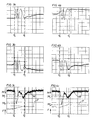
- the functional features of the methods according to the invention and the operation order of the impulse tool during a tightening process including a number of successive torque impulses delivered to a screw joint are illustrated by the diagrams 3 a-c to 6a-c. These diagrams are plotted from measurements made during a real tightening process. The diagrams show signals representing the rotational movement of the screw joint as well as measurements representing the torque delivered to the joint and the clamping force or tension magnitude obtained in the joint during four different impulses representing four different tightening stages of the same tightening process.
- Figs.3a-c The first one of the described impulses delivered to the joint is illustrated in Figs.3a-c.
- Fig. 3a there is shown the rotation related signal delivered by one of the sensing elements 30,31
- Fig. 3b show the rotation related signal delivered by the other one of the sensing elements 30,31.
- the diagrams show the rotation signal in relation to time, and the wave formed curves reflect the magnetic influence of a succession of teeth 28 passing by the sensing elements 30,31 at rotational movement of the output shaft 13.
- the screw joint position at the end of the accomplished rotational increment is marked with ⁇ I and has a corresponding location in all three diagrams 3a-c.
- a signal representing the torque M delivered to the screw joint and a signal representing the obtained clamping force or tension F in the joint.
- the clamping force F is obtained from a sensor mounted directly on the screw joint. This arrangement is used for experimental purposes only, because if you always have access to the actual clamping force in the joint during tightening the new method for obtaining a more accurate measurement of the installed torque would be meaningless. Accordingly, the clamping force sensor is used just for obtaining a diagrammatical illustration of the tension increase during each impulse, particularly when illustrated in a direct comparison with the torque/time curve.
- Fig. 3c there is also illustrated the growth of the clamping force F during a torque impulse delivered to the joint.
- the clamping force F starts increasing as the joint starts rotating and continues to increase until the joint stops rotating, as illustrated by the point ⁇ I .
- the slight wave form of the torque/time curve i.e. the occurrence of a second lower peak, is due to dynamic forces and elasticity in the power train of the tightening tool.
- Figs. 4a-c, 5a-c and 6a-c there are shown curves reflecting the rotational movement of the screw joint as well as the detected torque and clamping force magnitudes during three later torque pulses delivered to the joint during the same tightening process. It is clearly shown that the pulses are successively shorter as the joint is further tightened, and that the secondary torque peak tends to merge with the main torque peak as the tightening process approaches the final pretension condition. See Fig. 6c.
- the four different torque pulses illustrated in Figs. 3a-c, 4a-c, 5a-c and 6a-c, respectively, show clearly by way of examples that the main torque peak value previously used for determining the tightening state of the screw joint does not represent the torque magnitude that corresponds to the obtained clamping force in the joint. Even though at a later tightening stage the rotation stop point ⁇ I of each impulse is closer to the torque peak point, there is still a substantial difference between the peak level M P and the installed torque M I . See Fig. 6c.
- the per impulse increasing installed torque M I which is detected at the point where the screw joint rotation ceases at each impulse, is used for determining when the joint is tightened to the predetermined torque target level.
Landscapes
- Engineering & Computer Science (AREA)
- Mechanical Engineering (AREA)
- Details Of Spanners, Wrenches, And Screw Drivers And Accessories (AREA)
- Force Measurement Appropriate To Specific Purposes (AREA)
Applications Claiming Priority (2)
| Application Number | Priority Date | Filing Date | Title |
|---|---|---|---|
| SE9703896A SE511336C2 (sv) | 1997-10-27 | 1997-10-27 | Metod för fastställande av det installerade momentet i ett skruvförband vid impulsåtdragning, metod för styrning av en åtdragningsprocess, metod för kvalitetsövervakning och ett momentimpulsverktyg för åtdragning av skruvförband |
| SE9703896 | 1997-10-27 |
Publications (3)
| Publication Number | Publication Date |
|---|---|
| EP0911119A2 true EP0911119A2 (de) | 1999-04-28 |
| EP0911119A3 EP0911119A3 (de) | 2000-03-29 |
| EP0911119B1 EP0911119B1 (de) | 2002-06-19 |
Family
ID=20408741
Family Applications (1)
| Application Number | Title | Priority Date | Filing Date |
|---|---|---|---|
| EP98850165A Expired - Lifetime EP0911119B1 (de) | 1997-10-27 | 1998-10-22 | Verfahren zum Feststellen des Drehmoments in einer mittels drehschlagverschraubten erzeugten Schraubverbindung und Drehschlag-Werkzeug zum Erzeugen einer Schraubverbindung mit vorgegebenem Drehmoment |
Country Status (5)
| Country | Link |
|---|---|
| US (2) | US6134973A (de) |
| EP (1) | EP0911119B1 (de) |
| JP (1) | JP4564604B2 (de) |
| DE (1) | DE69806113T2 (de) |
| SE (1) | SE511336C2 (de) |
Cited By (13)
| Publication number | Priority date | Publication date | Assignee | Title |
|---|---|---|---|---|
| EP1000710A1 (de) * | 1998-11-16 | 2000-05-17 | Renault | Verfahren zum Messen und/oder Ansteuern bei einer Schraubvorrichtung mit einem hydropneumatischen Impulsschrauber |
| WO2001047669A1 (en) * | 1999-12-23 | 2001-07-05 | Abb Ab | Method, device and system for determining torque |
| EP1059145A3 (de) * | 1999-06-11 | 2003-07-16 | Matsushita Electric Works, Ltd. | Schlag-angetriebene, drehende Vorrichtung |
| EP1257034A3 (de) * | 2001-05-09 | 2004-04-14 | Makita Corporation | Kraftwerkzeuge |
| WO2004018153A3 (en) * | 2002-08-23 | 2004-04-29 | Fast Technology Ag | Torque sensor adaptor |
| EP1250580A4 (de) * | 1999-12-16 | 2006-03-15 | Magna Lastic Devices Inc | VERFAHREN UND APPARAT ZUR STENORUNG EINES SCHLAGWERKEZEUGS UND DEREN VERWENDUNG IN EINEM SCHLAGGERäT |
| US10052733B2 (en) | 2015-06-05 | 2018-08-21 | Ingersoll-Rand Company | Lighting systems for power tools |
| US10418879B2 (en) | 2015-06-05 | 2019-09-17 | Ingersoll-Rand Company | Power tool user interfaces |
| US10615670B2 (en) | 2015-06-05 | 2020-04-07 | Ingersoll-Rand Industrial U.S., Inc. | Power tool user interfaces |
| US10668614B2 (en) | 2015-06-05 | 2020-06-02 | Ingersoll-Rand Industrial U.S., Inc. | Impact tools with ring gear alignment features |
| EP3632625A4 (de) * | 2017-05-30 | 2020-06-03 | Panasonic Intellectual Property Management Co., Ltd. | Elektrowerkzeug |
| US11260517B2 (en) | 2015-06-05 | 2022-03-01 | Ingersoll-Rand Industrial U.S., Inc. | Power tool housings |
| US11491616B2 (en) | 2015-06-05 | 2022-11-08 | Ingersoll-Rand Industrial U.S., Inc. | Power tools with user-selectable operational modes |
Families Citing this family (33)
| Publication number | Priority date | Publication date | Assignee | Title |
|---|---|---|---|---|
| SE511336C2 (sv) * | 1997-10-27 | 1999-09-13 | Atlas Copco Tools Ab | Metod för fastställande av det installerade momentet i ett skruvförband vid impulsåtdragning, metod för styrning av en åtdragningsprocess, metod för kvalitetsövervakning och ett momentimpulsverktyg för åtdragning av skruvförband |
| US6581696B2 (en) * | 1998-12-03 | 2003-06-24 | Chicago Pneumatic Tool Company | Processes of determining torque output and controlling power impact tools using a torque transducer |
| US6158528A (en) * | 2000-01-27 | 2000-12-12 | S.P. Air Kabusiki Kaisha | Hand-held pneumatic rotary drive device |
| JP4721535B2 (ja) * | 2001-02-28 | 2011-07-13 | 勝行 戸津 | 電動回転工具 |
| SE519292C2 (sv) * | 2001-04-17 | 2003-02-11 | Atlas Copco Tools Ab | Metod och verktyg innefattande bestämning av överfört moment som funktion av retardation och tröghetsmoment |
| JP2003200363A (ja) * | 2001-12-26 | 2003-07-15 | Makita Corp | バッテリ式電動工具 |
| EP1439035A1 (de) * | 2002-12-16 | 2004-07-21 | Fast Technology AG | Signalverarbeitungs- und Steuerungsvorrichtung für ein Drehmomentwerkzeug |
| US7062979B2 (en) * | 2003-03-19 | 2006-06-20 | The Boeing Company | Tool and associated methods for controllably applying torque to a fastener |
| US7162320B2 (en) * | 2003-03-31 | 2007-01-09 | Honda Motor Co., Ltd. | Assembly line quality control |
| SE525666C2 (sv) * | 2003-07-07 | 2005-03-29 | Atlas Copco Tools Ab | Metod för kvalitetssäkring av skruvförbandsåtdragning |
| US6871153B1 (en) * | 2003-11-20 | 2005-03-22 | C.E. Electronics, Inc. | Dynamic calibration qualifier |
| SE526964C2 (sv) * | 2003-12-29 | 2005-11-29 | Atlas Copco Tools Ab | Metod för funktionsstyrning av en pneumatisk impulsmutterdragare samt ett kraftskruvdragarsystem |
| DE102004003202B4 (de) * | 2004-01-22 | 2022-05-25 | Robert Bosch Gmbh | Handgriff mit Erfassungseinrichtung |
| SE527512C2 (sv) * | 2004-04-01 | 2006-03-28 | Atlas Copco Tools Ab | Metod för bestämning av vinkelrörelsen hos den utgående axeln hos en impulsmutterdragare vid åtdragning av skruvförband |
| SE528114C2 (sv) * | 2004-09-20 | 2006-09-05 | Atlas Copco Tools Ab | Metod för kvalitetskontroll av ett skruvåtdragningsförlopp genomfört medelst en impulsmutterdragare |
| US7089080B1 (en) * | 2005-08-02 | 2006-08-08 | C.E. Electronics | Pulse tool controller |
| DE102006017193A1 (de) * | 2006-04-12 | 2007-10-25 | Robert Bosch Gmbh | Verfahren zum Anziehen einer Schraubverbindung und Schraubwerkzeug |
| DE102007045695A1 (de) * | 2007-09-24 | 2009-04-02 | Hs-Technik Gmbh | Hydropneumatischer Impulsschrauber und Verfahren zur Steuerung eines hydropneumatischen Impulsschraubers |
| DE102007057082A1 (de) * | 2007-11-21 | 2009-05-28 | Newfrey Llc, Newark | Kontaktiereinheit, Befestigungsverfahren und Schraubwerkzeug zur Durchführung des Verfahrens |
| SE531828C2 (sv) * | 2007-12-05 | 2009-08-18 | Atlas Copco Tools Ab | Ett kraftverktyg och en metod för användning av kraftverktyget |
| CN102015216B (zh) * | 2008-03-17 | 2013-10-23 | 史丹利百得有限公司 | 不连续的驱动工具组件以及检测其转动角的方法 |
| TW200950306A (en) * | 2008-06-10 | 2009-12-01 | Mobiletron Electronics Co Ltd | Electric motor resistance torque control and battery discharging protection circuit |
| DE102009046789A1 (de) * | 2009-11-17 | 2011-05-19 | Robert Bosch Gmbh | Handwerkzeugmaschinenvorrichtung |
| SE535392C2 (sv) * | 2010-09-30 | 2012-07-24 | Atlas Copco Tools Ab | Metod för bestämning av kvaliteten vid åtdragning av ett skruvförband |
| DE102011075859B4 (de) * | 2011-05-16 | 2022-07-07 | Bayerische Motoren Werke Aktiengesellschaft | Prüfvorrichtung für Impulsschrauber mit einem Testschraubbolzen |
| EP2535139B1 (de) * | 2011-06-17 | 2016-04-06 | Dino Paoli S.r.l. | Schlagwerkzeug |
| DE202011110326U1 (de) * | 2011-09-01 | 2013-07-01 | Hwa Ag | Anlage zum Montieren von Fahrzeugrädern |
| US9701000B2 (en) * | 2013-07-19 | 2017-07-11 | Panasonic Intellectual Property Management Co., Ltd. | Impact rotation tool and impact rotation tool attachment |
| KR200490007Y1 (ko) | 2015-04-28 | 2019-11-04 | 밀워키 일렉트릭 툴 코포레이션 | 정밀 토크 스크류드라이버 |
| US10357871B2 (en) | 2015-04-28 | 2019-07-23 | Milwaukee Electric Tool Corporation | Precision torque screwdriver |
| JP6906196B2 (ja) * | 2017-05-30 | 2021-07-21 | パナソニックIpマネジメント株式会社 | 電動工具 |
| JP7592844B2 (ja) | 2020-08-10 | 2024-12-02 | ミルウォーキー エレクトリック ツール コーポレイション | クラッチ設定センサを備える電動ドライバ |
| CN113324862B (zh) * | 2021-07-13 | 2022-05-06 | 广东省医疗器械质量监督检验所 | 腹膜透析外接管的模拟临床耐疲劳测试方法及装置 |
Family Cites Families (18)
| Publication number | Priority date | Publication date | Assignee | Title |
|---|---|---|---|---|
| US4185701A (en) * | 1975-05-19 | 1980-01-29 | Sps Technologies, Inc. | Tightening apparatus |
| BR7707762A (pt) * | 1976-11-22 | 1978-06-20 | Atlas Copco Ab | Aperfeicoamento em processo e em aparelho para protender uma junta roscada a predeterminada carga axial |
| US4142591A (en) * | 1977-06-29 | 1979-03-06 | S. Himmelstein And Company | Torque-yield control system |
| US4361945A (en) * | 1978-06-02 | 1982-12-07 | Rockwell International Corporation | Tension control of fasteners |
| US4316512A (en) * | 1979-04-04 | 1982-02-23 | Sps Technologies, Inc. | Impact wrench |
| JPS58132426A (ja) * | 1982-02-02 | 1983-08-06 | Nitto Seiko Co Ltd | 自動ねじ締め機 |
| SE459327B (sv) * | 1984-12-21 | 1989-06-26 | Atlas Copco Ab | Hydrauliskt momentimpulsverk |
| SE446070B (sv) * | 1984-12-21 | 1986-08-11 | Atlas Copco Ab | Hydrauliskt momentimpulsverk for vridmomentalstrande verktyg |
| US5094301A (en) * | 1990-01-05 | 1992-03-10 | Dresser Industries, Inc. | Programmable pulsed torque recovery system |
| US5366026A (en) * | 1992-08-28 | 1994-11-22 | Nissan Motor Company, Ltd. | Impact type clamping apparatus |
| JP2953211B2 (ja) * | 1992-09-07 | 1999-09-27 | 日産自動車株式会社 | インパクト式ねじ締め装置 |
| DE4243069C2 (de) * | 1992-12-18 | 2001-09-27 | Gardner Denver Gmbh | Impulswerkzeug, insbesondere Impulsschrauber |
| DE4336465A1 (de) * | 1993-10-26 | 1995-04-27 | Bosch Gmbh Robert | Schlag- oder Impulsschraubverfahren |
| SE506118C2 (sv) * | 1993-09-02 | 1997-11-10 | Atlas Copco Tools Ab | Metod för åtdragning av gängade förband till en önskad förspänningsnivå med hjälp av en manuellt manövrerad kraftmutterdragare innefattande en nedgängningsfas och en förspänningsfas, avkänning av momentmotståndet i förbandet samt avbrytande av rotationen vid uppnådd önskad förspänningsnivå |
| JPH07308865A (ja) * | 1994-05-13 | 1995-11-28 | Nissan Motor Co Ltd | インパクト式ねじ締め装置 |
| DE4429282A1 (de) * | 1994-08-18 | 1996-02-22 | Cooper Ind Inc | Hydro-Impulsschrauber insbesondere zum Anziehen von Schraubverbindungen |
| JPH1071576A (ja) * | 1996-06-20 | 1998-03-17 | Nissan Motor Co Ltd | インパクト式ねじ締め方法と装置 |
| SE511336C2 (sv) * | 1997-10-27 | 1999-09-13 | Atlas Copco Tools Ab | Metod för fastställande av det installerade momentet i ett skruvförband vid impulsåtdragning, metod för styrning av en åtdragningsprocess, metod för kvalitetsövervakning och ett momentimpulsverktyg för åtdragning av skruvförband |
-
1997
- 1997-10-27 SE SE9703896A patent/SE511336C2/sv unknown
-
1998
- 1998-10-22 DE DE69806113T patent/DE69806113T2/de not_active Expired - Lifetime
- 1998-10-22 EP EP98850165A patent/EP0911119B1/de not_active Expired - Lifetime
- 1998-10-26 US US09/178,999 patent/US6134973A/en not_active Expired - Lifetime
- 1998-10-27 JP JP30605698A patent/JP4564604B2/ja not_active Expired - Lifetime
-
2000
- 2000-08-15 US US09/639,002 patent/US6341533B1/en not_active Expired - Lifetime
Cited By (19)
| Publication number | Priority date | Publication date | Assignee | Title |
|---|---|---|---|---|
| FR2785986A1 (fr) * | 1998-11-16 | 2000-05-19 | Renault | Procede de mesure et/ou de commande d'un equipement de vissage comprenant une visseuse hydropneumatique a martelement |
| EP1000710A1 (de) * | 1998-11-16 | 2000-05-17 | Renault | Verfahren zum Messen und/oder Ansteuern bei einer Schraubvorrichtung mit einem hydropneumatischen Impulsschrauber |
| EP1059145A3 (de) * | 1999-06-11 | 2003-07-16 | Matsushita Electric Works, Ltd. | Schlag-angetriebene, drehende Vorrichtung |
| EP1250580A4 (de) * | 1999-12-16 | 2006-03-15 | Magna Lastic Devices Inc | VERFAHREN UND APPARAT ZUR STENORUNG EINES SCHLAGWERKEZEUGS UND DEREN VERWENDUNG IN EINEM SCHLAGGERäT |
| WO2001047669A1 (en) * | 1999-12-23 | 2001-07-05 | Abb Ab | Method, device and system for determining torque |
| EP2256899A1 (de) * | 2001-05-09 | 2010-12-01 | Makita Corporation | Kraftwerkzeuge |
| US7109675B2 (en) | 2001-05-09 | 2006-09-19 | Makita Corporation | Power tools |
| EP1257034A3 (de) * | 2001-05-09 | 2004-04-14 | Makita Corporation | Kraftwerkzeuge |
| WO2004018153A3 (en) * | 2002-08-23 | 2004-04-29 | Fast Technology Ag | Torque sensor adaptor |
| US10668614B2 (en) | 2015-06-05 | 2020-06-02 | Ingersoll-Rand Industrial U.S., Inc. | Impact tools with ring gear alignment features |
| US10418879B2 (en) | 2015-06-05 | 2019-09-17 | Ingersoll-Rand Company | Power tool user interfaces |
| US10615670B2 (en) | 2015-06-05 | 2020-04-07 | Ingersoll-Rand Industrial U.S., Inc. | Power tool user interfaces |
| US10052733B2 (en) | 2015-06-05 | 2018-08-21 | Ingersoll-Rand Company | Lighting systems for power tools |
| US11260517B2 (en) | 2015-06-05 | 2022-03-01 | Ingersoll-Rand Industrial U.S., Inc. | Power tool housings |
| US11491616B2 (en) | 2015-06-05 | 2022-11-08 | Ingersoll-Rand Industrial U.S., Inc. | Power tools with user-selectable operational modes |
| US11602832B2 (en) | 2015-06-05 | 2023-03-14 | Ingersoll-Rand Industrial U.S., Inc. | Impact tools with ring gear alignment features |
| US11707831B2 (en) | 2015-06-05 | 2023-07-25 | Ingersoll-Rand Industrial U.S., Inc. | Power tool housings |
| US11784538B2 (en) | 2015-06-05 | 2023-10-10 | Ingersoll-Rand Industrial U.S., Inc. | Power tool user interfaces |
| EP3632625A4 (de) * | 2017-05-30 | 2020-06-03 | Panasonic Intellectual Property Management Co., Ltd. | Elektrowerkzeug |
Also Published As
| Publication number | Publication date |
|---|---|
| SE9703896L (sv) | 1999-04-28 |
| JPH11254340A (ja) | 1999-09-21 |
| SE511336C2 (sv) | 1999-09-13 |
| US6134973A (en) | 2000-10-24 |
| JP4564604B2 (ja) | 2010-10-20 |
| DE69806113D1 (de) | 2002-07-25 |
| US6341533B1 (en) | 2002-01-29 |
| EP0911119B1 (de) | 2002-06-19 |
| EP0911119A3 (de) | 2000-03-29 |
| SE9703896D0 (sv) | 1997-10-27 |
| DE69806113T2 (de) | 2003-01-23 |
Similar Documents
| Publication | Publication Date | Title |
|---|---|---|
| US6134973A (en) | Method for determining the installed torque in a screw joint at impulse tightening and a torque impulse tool for tightening a screw joint to a predetermined torque level | |
| US4110829A (en) | Apparatus for and method of determining rotational and linear stiffness | |
| US3982419A (en) | Apparatus for and method of determining rotational and linear stiffness | |
| US4344216A (en) | Apparatus and method for tightening an assembly | |
| US9021896B2 (en) | Method for determining the quality of a screw joint tightening process performed by an impulse wrench | |
| US3973434A (en) | Tightening system with quality control apparatus | |
| EP1379361B1 (de) | Verfahren und vorrichtung zum bestimmen des an ein befestigungselement angelegten drehmoments als eine funktion der verzögerung und des trägheitsmoments | |
| US7467669B2 (en) | Method for governing the operation of a pneumatic impulse wrench and a power screw joint tightening tool system | |
| GB2048494A (en) | Impact wrench | |
| GB1592984A (en) | Method and apparatus for tightening screwthreaded joints | |
| JP2005279865A (ja) | 衝撃式締付工具 | |
| JPH08267368A (ja) | トルク制御式パルスツール | |
| US7958611B2 (en) | Method for quality checking a screw joint tightening process performed by a torque impulse wrench | |
| EP3389928B1 (de) | Impulsschrauberrotationsdetektion | |
| CN214793575U (zh) | 螺栓锁固作业用的螺栓夹紧力传感器 | |
| WO2026068125A1 (en) | Pulse tool for tightening joints | |
| JP2005125425A (ja) | 衝撃式締付工具 | |
| CA1054826A (en) | Apparatus for and method of determining rotational or linear stiffness | |
| JPS597568A (ja) | 動力工具 |
Legal Events
| Date | Code | Title | Description |
|---|---|---|---|
| PUAI | Public reference made under article 153(3) epc to a published international application that has entered the european phase |
Free format text: ORIGINAL CODE: 0009012 |
|
| AK | Designated contracting states |
Kind code of ref document: A2 Designated state(s): DE FR GB IT |
|
| AX | Request for extension of the european patent |
Free format text: AL;LT;LV;MK;RO;SI |
|
| PUAL | Search report despatched |
Free format text: ORIGINAL CODE: 0009013 |
|
| AK | Designated contracting states |
Kind code of ref document: A3 Designated state(s): AT BE CH CY DE DK ES FI FR GB GR IE IT LI LU MC NL PT SE |
|
| AX | Request for extension of the european patent |
Free format text: AL;LT;LV;MK;RO;SI |
|
| RIC1 | Information provided on ipc code assigned before grant |
Free format text: 7B 25B 23/14 A, 7B 25B 23/145 B, 7B 23P 19/06 B |
|
| 17P | Request for examination filed |
Effective date: 20000826 |
|
| AKX | Designation fees paid |
Free format text: DE FR GB IT |
|
| GRAG | Despatch of communication of intention to grant |
Free format text: ORIGINAL CODE: EPIDOS AGRA |
|
| 17Q | First examination report despatched |
Effective date: 20010319 |
|
| GRAG | Despatch of communication of intention to grant |
Free format text: ORIGINAL CODE: EPIDOS AGRA |
|
| GRAH | Despatch of communication of intention to grant a patent |
Free format text: ORIGINAL CODE: EPIDOS IGRA |
|
| GRAH | Despatch of communication of intention to grant a patent |
Free format text: ORIGINAL CODE: EPIDOS IGRA |
|
| GRAA | (expected) grant |
Free format text: ORIGINAL CODE: 0009210 |
|
| AK | Designated contracting states |
Kind code of ref document: B1 Designated state(s): DE FR GB IT |
|
| REG | Reference to a national code |
Ref country code: GB Ref legal event code: FG4D |
|
| REF | Corresponds to: |
Ref document number: 69806113 Country of ref document: DE Date of ref document: 20020725 |
|
| ET | Fr: translation filed | ||
| PLBE | No opposition filed within time limit |
Free format text: ORIGINAL CODE: 0009261 |
|
| STAA | Information on the status of an ep patent application or granted ep patent |
Free format text: STATUS: NO OPPOSITION FILED WITHIN TIME LIMIT |
|
| 26N | No opposition filed |
Effective date: 20030320 |
|
| REG | Reference to a national code |
Ref country code: FR Ref legal event code: PLFP Year of fee payment: 18 |
|
| REG | Reference to a national code |
Ref country code: DE Ref legal event code: R082 Ref document number: 69806113 Country of ref document: DE Representative=s name: PATENTANWAELTE OLBRICHT, BUCHHOLD, KEULERTZ PA, DE |
|
| REG | Reference to a national code |
Ref country code: FR Ref legal event code: PLFP Year of fee payment: 19 |
|
| REG | Reference to a national code |
Ref country code: FR Ref legal event code: PLFP Year of fee payment: 20 |
|
| PGFP | Annual fee paid to national office [announced via postgrant information from national office to epo] |
Ref country code: FR Payment date: 20171025 Year of fee payment: 20 Ref country code: DE Payment date: 20171027 Year of fee payment: 20 |
|
| PGFP | Annual fee paid to national office [announced via postgrant information from national office to epo] |
Ref country code: GB Payment date: 20171027 Year of fee payment: 20 Ref country code: IT Payment date: 20171024 Year of fee payment: 20 |
|
| REG | Reference to a national code |
Ref country code: DE Ref legal event code: R071 Ref document number: 69806113 Country of ref document: DE |
|
| REG | Reference to a national code |
Ref country code: GB Ref legal event code: PE20 Expiry date: 20181021 |
|
| PG25 | Lapsed in a contracting state [announced via postgrant information from national office to epo] |
Ref country code: GB Free format text: LAPSE BECAUSE OF EXPIRATION OF PROTECTION Effective date: 20181021 |