EP0911221A2 - Système de communication multiplexé monté sur véhicule - Google Patents
Système de communication multiplexé monté sur véhicule Download PDFInfo
- Publication number
- EP0911221A2 EP0911221A2 EP98120021A EP98120021A EP0911221A2 EP 0911221 A2 EP0911221 A2 EP 0911221A2 EP 98120021 A EP98120021 A EP 98120021A EP 98120021 A EP98120021 A EP 98120021A EP 0911221 A2 EP0911221 A2 EP 0911221A2
- Authority
- EP
- European Patent Office
- Prior art keywords
- multiplex communication
- communication apparatus
- circuit
- multiplex
- various kinds
- Prior art date
- Legal status (The legal status is an assumption and is not a legal conclusion. Google has not performed a legal analysis and makes no representation as to the accuracy of the status listed.)
- Ceased
Links
- 238000004891 communication Methods 0.000 title claims abstract description 154
- 238000001514 detection method Methods 0.000 description 16
- 230000005856 abnormality Effects 0.000 description 14
- 238000010420 art technique Methods 0.000 description 11
- 238000000034 method Methods 0.000 description 11
- 238000010586 diagram Methods 0.000 description 6
- 230000002159 abnormal effect Effects 0.000 description 2
- 230000005540 biological transmission Effects 0.000 description 2
- 230000008859 change Effects 0.000 description 2
- 239000000470 constituent Substances 0.000 description 2
- 230000008901 benefit Effects 0.000 description 1
- 230000003247 decreasing effect Effects 0.000 description 1
- 238000005516 engineering process Methods 0.000 description 1
- 230000007613 environmental effect Effects 0.000 description 1
- 239000000284 extract Substances 0.000 description 1
- 238000012905 input function Methods 0.000 description 1
- 230000010354 integration Effects 0.000 description 1
- 238000004519 manufacturing process Methods 0.000 description 1
- 230000009467 reduction Effects 0.000 description 1
- 230000008439 repair process Effects 0.000 description 1
- 239000011347 resin Substances 0.000 description 1
- 229920005989 resin Polymers 0.000 description 1
- 230000007480 spreading Effects 0.000 description 1
- 239000002699 waste material Substances 0.000 description 1
Images
Classifications
-
- B—PERFORMING OPERATIONS; TRANSPORTING
- B60—VEHICLES IN GENERAL
- B60R—VEHICLES, VEHICLE FITTINGS, OR VEHICLE PARTS, NOT OTHERWISE PROVIDED FOR
- B60R16/00—Electric or fluid circuits specially adapted for vehicles and not otherwise provided for; Arrangement of elements of electric or fluid circuits specially adapted for vehicles and not otherwise provided for
- B60R16/02—Electric or fluid circuits specially adapted for vehicles and not otherwise provided for; Arrangement of elements of electric or fluid circuits specially adapted for vehicles and not otherwise provided for electric constitutive elements
- B60R16/03—Electric or fluid circuits specially adapted for vehicles and not otherwise provided for; Arrangement of elements of electric or fluid circuits specially adapted for vehicles and not otherwise provided for electric constitutive elements for supply of electrical power to vehicle subsystems or for
- B60R16/0315—Electric or fluid circuits specially adapted for vehicles and not otherwise provided for; Arrangement of elements of electric or fluid circuits specially adapted for vehicles and not otherwise provided for electric constitutive elements for supply of electrical power to vehicle subsystems or for using multiplexing techniques
Definitions
- the present invention relates to a vehicle mounted multiplex communication system in which a plurality of multiplex communication apparatuses are connected to communication lines so as to be able to communicate mutually and at least one of the plurality of multiplex communication apparatuses is housed within a joint box integrally therewith.
- On and off signals or the like from such a plurality of operation switches are transmitted to the driving systems of the respective portions of an automobile.
- the detection signals from sensors disposed in the vicinity of the driving systems are transmitted to a central control portion disposed at the rear side of the install panel. Further, it is reported to an originator as to whether or not the transmitted signal has been surely received at a destination.
- an originator as to whether or not the transmitted signal has been surely received at a destination.
- the vehicle mounted multiplex communication system has been employed as one of communication methods for preventing such interference or crosstalk.
- the frequency division multiplex method for changing communication frequency in accordance with the kinds of signal there have been employed the frequency division multiplex method for changing communication frequency in accordance with the kinds of signal, the time division multiplex method in which simultaneous transmission of different kinds of signals is avoided by finely allocating signals to transmission time frames in accordance with a predetermined procedure, and the code division multiplex method for transmitting signals by differentiating the PN series used for signal spreading at every kind of signals.
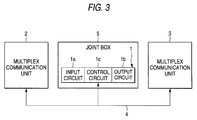
- a plurality of multiplex communication apparatuses 1 to 3 are connected to one or more communication medium (wiring path) 4 so that data is transmitted and received among these multiplex communication apparatuses 1 to 3.
- These multiplex communication apparatuses 1 to 3 are classified into two kinds of multiplex communication apparatuses, that is, a multiplex communication apparatus (reference numeral 1) operated in integration with a joint box 5, and multiplex communication apparatuses (reference numerals 2 and 3) operated individually.
- the former multiplex communication apparatus 1 is used, in many cases, in the vicinity of a central control portion since the joint box 5 can be connected easily and is made compact despite that it has a brunching function.
- the former multiplex communication apparatus 1 is formed by an input circuit 1a connected to signal input function parts such as operation switches etc., an output circuit 1b connected to signal output function parts such as lamps etc., and a control circuit 1c for controlling these circuits.
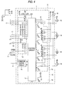
- Fig. 4 shows an example of the circuit arrangement of the multiplex communication apparatus 1 according to the aforesaid third prior art technique (3).
- the multiplex communication apparatus 1 includes an input circuit 1a connected to various kinds of switches etc. 11 such as an ignition switch, a small light switch, a door lock switch or the like and sensors etc. 12 such as a vehicle speed sensor or the like; an output circuit 1b connected to various kinds of loads, that is, lamps etc. 13 such as a room lamp, a foot lamp or the like and driving motor systems 14 such as a door lock motor, a power window motor or the like; an abnormality detection circuit 6 for detecting the abnormal state in the output circuit 1b at the time of the failure etc.
- switches etc. 11 such as an ignition switch, a small light switch, a door lock switch or the like and sensors etc. 12 such as a vehicle speed sensor or the like
- an output circuit 1b connected to various kinds of loads, that is, lamps etc. 13 such as a room lamp, a foot lamp or the like and driving motor systems 14
- any of the loads 13, 14 within the multiplex communication apparatus 1 operates abnormally.
- the control circuit 1c detects the abnormality of the current flowing through the various kinds of loads 13, 14 through the operation of the abnormality detection circuit 6, and controls the output circuit 1b suitably in accordance with the detection result thereby to cut off the current supplied to the various kinds of loads 13, 14.
- a buzzer 17b is sounded to notify a driver etc. of the occurrence of abnormality or that the operation has not been terminated.
- a reference numeral 15 in Fig. 4 depicts a communication circuit for converting signal into data format suitable for communication between the wiring path 4 connected to an external circuit and the control circuit 1c of the multiplex communication apparatus 1.
- a reference numeral 18 depicts a fuse provided for dealing with the case where an overcurrent is generated at the driving motor system 14. Even if such a fuse 18 is provided, for example, if an environmental wire is erroneously broken at the time of mounting or repairing the driving motor system 14, the fuse 18 may not be blown depending on the state of the short-circuit. As a consequence, various kinds of parts and circuits such as a relay within the output circuit 1b may be burn and broken. In such a case, the role of the abnormality detection circuit 6 was not negligible.
- portions liable to become failure in an automobile are the loads 13, 14 such as the room lamp, various kinds of driving motor systems or the like, as described above. Accordingly, a portion liable to become failure due to the burning of the element within the multiplex communication apparatus 1 is the output circuit 1b connected to the various kinds of the loads 13, 14. Further, in some case, the control circuit 1c may become failure due to the failire of the output circuit 1b.
- the input circuit 1a originally not necessary to be exchanged must also be exchanged for a new one. Thus, there arises a problem that the normal input circuit 1a is disposed.
- an object of the present invention is to provide a multiplex communication apparatus which is able to reduce the cost thereof by eliminating an abnormality detection circuit and to eliminate such a waste that an input circuit as well as an output circuit are exchanged for new ones at the time of the failure of the output circuit due to the failure of various kinds of loads.
- the vehicle mounted multiplex communication system for effecting multiplex communication through a communication line among a plurality of multiplex communication apparatuses mounted within a vehicle, comprises: at least one first multiplex communication apparatus, which is at least one of the plurality of multiplex communication apparatuses, housed within a joint box integrally therewith; and a second multiplex communication apparatus, which is another of said plurality of multiplex communication apparatuses, disposed separately from the joint box and effecting multiplex communication with the first multiplex communication apparatus through the communication line, wherein the first multiplex communication apparatus includes an input circuit connected to various kinds of signal input means including various kinds of operation switches and sensors or the like disposed at respective portions of the vehicle, a first control circuit for controlling the input circuit, and a first communication circuit for converting signal from the first control circuit into data format suitable for communication through the communication line, and wherein the second multiplex communication apparatus includes an output circuit for changing loads to be driven including various kinds of lamps etc. for display and various kinds of driving systems, a second control circuit
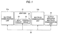
- Fig. 1 is a schematic diagram showing the entire arrangement of a vehicle mounted multiplex communication system according to the first embodiments of the present invention
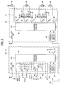
- Fig. 2 is a schematic circuit diagram showing the arrangement of a part of the vehicle mounted multiplex communication system.
- the multiplex communication system according to the first embodiment is arranged in the following manner. That is, as shown in Fig. 1, an output circuit (corresponding to the block 1b in Fig. 4) for changing loads to be driven which may be broken due to external reason is removed from a multiplex communication apparatus 22 (first multiplex communication apparatus) housed within a joint box 21, and the multiplex communication apparatus 22 is formed by an input circuit 23 and a control circuit 24. Further, the output circuit for changing loads to be driven is replaced by connecting an individual output-dedicated multiplex communication apparatus 25 (second multiplex communication apparatus) to a bus line, that is, a multiplex line (communication line) 26 separately from other multiplex communication apparatuses.
- an output circuit (corresponding to the block 1b in Fig. 4) for changing loads to be driven which
- the joint box 21 is a generally known casing having outer wall portions formed by insulative resin or the like and a connector chamber for connecting the multiplex line 26 at one end of the outer wall portion.
- the multiplex communication apparatus 22 has a package casing, for protecting internal circuits and various kinds of electronic parts contained therein, which is integrally formed with the outer wall portions of the joint box 21. Since the output circuit is removed from the multiplex communication apparatus 22, the possibility of the failure of the multiplex communication apparatus 22 becomes quite low and hence the necessity for replacing the multiplex communication apparatus 22 with a new one becomes also quite low. Accordingly, the multiplex communication apparatus 22 is arranged such that it can not be separated from the joint box 21 nor replaced with a new one in view of the easiness of manufacturing the system and the reduction of the number of parts thereof, or the like.
- the multiplex communication apparatus 22 includes an input circuit 23 connected to various kinds of switches etc. 31a, 31b such as an ignition switch, a small light switch, a door lock switch or the like and sensors etc. 32 such as a vehicle speed sensor or the like; a control circuit 24 for controlling the input circuit 23; a buzzer 33 being sounded upon operation of each of the various kinds of switches 31a, 31b; a sound change-over switch 34; and a communication circuit 35 for converting signal into data format suitable for, communication between the external multiplex line 26 and the control circuit 24.
- switches etc. 31a, 31b such as an ignition switch, a small light switch, a door lock switch or the like and sensors etc. 32 such as a vehicle speed sensor or the like
- a control circuit 24 for controlling the input circuit 23
- a buzzer 33 being sounded upon operation of each of the various kinds of switches 31a, 31b
- a sound change-over switch 34 and a communication circuit 35 for converting signal into data format suitable for, communication between the external multiplex line 26
- the input circuit 23 includes a plurality of signal lines which are wired from the various kinds of the switches etc. 31a, 31b and the sensors etc. 32 to the control circuit 24 independently and in parallel to one after another.
- the intermediate points of some of the respective signal lines are grounded through resistors R1 and the intermediate points of the remaining ones of the respective signal lines are connected to the battery of the automobile through resistors R2.
- the control circuit 24 detects the changes of the voltages at the respective signal lines caused by the operations of the various kinds of the switches etc. 31a, 31b and the sensors 32.
- the control circuit 24 detects the operation signals from the various kinds of the switches etc. 31a, 31b and the detection signals from the sensors etc. 32 obtained through the input circuit 23. Then, the control circuit synthesizes these signals from the input circuit in accordance with a predetermined communication method such as the frequency division multiplex method, time division multiplex method, code division multiplex method or the like so that these signals can be discriminated, thereby to output the synthesized signal to the communication circuit 35.
- a predetermined communication method such as the frequency division multiplex method, time division multiplex method, code division multiplex method or the like
- the communication circuit 35 outputs the synthesized signal transmitted from the control circuit 24 to the multiplex line 26 at suitable timings.
- the individual output-dedicated multiplex communication apparatus 25 includes an output circuit 41 which is removed from the multiplex communication apparatus 22, a control circuit 42 for controlling the output circuit 41, and a communication circuit 43 for outputting signals transmitting through the multiplex line 26 to the control circuit 42.
- the output circuit 41 is connected to various kinds of loads, that is, various kinds of lamps etc. 44 such as a room lamp, a foot lamp or the like and various kinds of driving motor systems 45 such as a door lock motor, a power window motor or the like, and selectively drives these loads.
- the output circuit includes lamp switching elements 46 which are turned on and off thereby to selectively supply driving currents to the various kinds of lamps etc. 44 in accordance with instruction signals from the control circuit 42, relays 47 which are selectively changed over thereby to selectively supply driving currents to the various kinds of the driving motor systems 45, and driving system switching elements 48 which are selectively turned on and off thereby to selectively close and open the relays 47 in accordance with instruction signals from the control circuit 42.
- the control circuit 42 has a function of separating or extracting the signals obtained from the multiplex line 26 through the communication circuit 43 in accordance with the predetermined communication method having been performed in the control circuit 24 of the multiplex communication apparatus 22 within the joint box 21, then selecting corresponding ones of the switching elements 46, 48 within the output circuit 41 in accordance with the separated or extracted signals thereby to output the drive instruction signals. Further, the control circuit has a function of returning a message that the control circuit has received the signals through the multiplex line 26 to the originator, that is, the multiplex communication apparatus 22 (or an individual multiplex communication apparatus 51a or 51b described later).
- Reference numerals 51a, 51b in Fig. 1 depict the individual multiplex communication apparatuses which correspond to the individual multiplex communication apparatuses 2, 3 in Fig. 3 and connected to the bus line, that is, the multiplex line 26 together with the multiplex communication apparatus 22 within the joint box 21 and the individual output-dedicated multiplex communication apparatus 25.
- a reference numeral 52 in Fig. 2 depicts a transformer for converting the output voltage of the battery (power supply).
- the various kinds of the switches etc. 31a, 31b connected to the input circuit 23 of the multiplex communication apparatus 22 are operated and the signals from the sensors etc. 32 depending on the circumferential condition are inputted into the input circuit 23.
- the voltages on the respective signal lines change.
- the control circuit 24 detects and determines such voltage changes in the signal lines, the control circuit synthesizes the signals from the input circuit in accordance with the predetermined communication method and supplies the synthesized signal to the multiplex line through the communication circuit 35.
- Such a synthesized signal is transmitted to the individual output-dedicated multiplex communication apparatus 25 and the individual multiplex communication apparatuses 51a, 51b.
- the control circuit 42 separates or extracts the signals obtained through the communication circuit 43 and selects corresponding ones of the switching elements 46, 48 within the output circuit 41 in accordance with the separated or extracted signals thereby to output the drive instruction signals.
- the switching elements 46, 48 within the output circuit 41 are turned on or closed thereby to turn on desired one(s) of the lamps etc. 44 or drive desired one(s) of the driving motor systems 45.
- the individual output-dedicated multiplex communication apparatus 25 does not include a circuit corresponding to the input circuit 23 provided in the multiplex communication apparatus 22 within the joint box 21, the cost for exchanging the individual output-dedicated multiplex communication apparatus for a new one can be made cheaper by the cost of the input circuit.
- portions which becomes failure due to the short-circuit are the portions of the output circuit 41 such as lamp driving control portion, a relay coil driving control or the like.
- the probability that the multiplex communication apparatus 22 within the joint box 21 having the input circuit 23 and the control circuit 24 as the main constituent elements becomes failure is quite low. Accordingly, unlike the aforesaid first to third prior art techniques, there scarcely arises any necessity of exchanging the multiplex communication apparatus 22 within the joint box 21 for a new one.
- an abnormality detection circuit (corresponding to the abnormality detection circuit 6 in Fig. 4) provided on the assumption of the failure due to the external reason is required to be provided in neither of the multiplex communication apparatus 22 within the joint box 21 nor the individual output-dedicated multiplex communication apparatus 25.
- the degree of freedom for designing the circuits within both the multiplex communication apparatuses 22, 25 can be improved.
- the multiplex communication apparatus 22 within the joint box 21 does not require the circuit (corresponding to the output circuit 1b in Fig. 4) corresponding to the output circuit 41 within the individual output-dedicated multiplex communication apparatus 25. Accordingly, the required space within the joint box 21 can be decreased.
- the various kinds of switches etc. 31a, 31b, sensors etc. 32, various kinds of the lamps etc. 44 and various kinds of the driving motor systems 45 are not limited to those described above, but other types thereof may be employed.
- the output circuit for changing load to be driven which is liable to become failure due to external reason
- the probability of the failure of the first multiplex communication apparatus can be reduced to a large extent.
- the circuit area for the first multiplex communication apparatus as well as the entire size of the joint box can be reduced to a large extent. Accordingly, the joint box becomes easy to handle.
Landscapes
- Engineering & Computer Science (AREA)
- Mechanical Engineering (AREA)
- Time-Division Multiplex Systems (AREA)
- Selective Calling Equipment (AREA)
- Small-Scale Networks (AREA)
Applications Claiming Priority (3)
| Application Number | Priority Date | Filing Date | Title |
|---|---|---|---|
| JP29417997 | 1997-10-27 | ||
| JP9294179A JPH11136222A (ja) | 1997-10-27 | 1997-10-27 | 車載多重通信システム |
| JP294179/97 | 1997-10-27 |
Publications (2)
| Publication Number | Publication Date |
|---|---|
| EP0911221A2 true EP0911221A2 (fr) | 1999-04-28 |
| EP0911221A3 EP0911221A3 (fr) | 2000-10-04 |
Family
ID=17804341
Family Applications (1)
| Application Number | Title | Priority Date | Filing Date |
|---|---|---|---|
| EP98120021A Ceased EP0911221A3 (fr) | 1997-10-27 | 1998-10-22 | Système de communication multiplexé monté sur véhicule |
Country Status (2)
| Country | Link |
|---|---|
| EP (1) | EP0911221A3 (fr) |
| JP (1) | JPH11136222A (fr) |
Cited By (1)
| Publication number | Priority date | Publication date | Assignee | Title |
|---|---|---|---|---|
| GB2549962A (en) * | 2016-05-04 | 2017-11-08 | Ford Global Tech Llc | A relay control box assembly |
Citations (3)
| Publication number | Priority date | Publication date | Assignee | Title |
|---|---|---|---|---|
| US4370561A (en) * | 1980-11-28 | 1983-01-25 | Rca Corporation | Vehicle multiplex system |
| DE19511755C1 (de) * | 1995-03-30 | 1996-08-22 | Framatome Connectors Int | Multiplex-Steuerung von Komponenten bzw. Untersystemen in Kraftfahrzeugen |
| WO1996026570A1 (fr) * | 1995-02-21 | 1996-08-29 | Hitachi, Ltd. | Appareil et procede de fourniture d'electricite a un vehicule, dispositif a circuits semiconducteurs a utiliser dans ledit appareil et dispositif de cablage commun pour une automobile ou un autre vehicule |
Family Cites Families (3)
| Publication number | Priority date | Publication date | Assignee | Title |
|---|---|---|---|---|
| US5307340A (en) * | 1991-04-02 | 1994-04-26 | The Furukawa Electric Co., Ltd. | Multipath transmission system with a troubleshooting arrangement for detecting failure |
| JP3303328B2 (ja) * | 1992-03-23 | 2002-07-22 | 日産自動車株式会社 | 車両用通信装置 |
| US5274636A (en) * | 1992-04-20 | 1993-12-28 | Chrysler Corporation | Automatic multiplex data link system, symbol encoder decoder therefor |
-
1997
- 1997-10-27 JP JP9294179A patent/JPH11136222A/ja active Pending
-
1998
- 1998-10-22 EP EP98120021A patent/EP0911221A3/fr not_active Ceased
Patent Citations (4)
| Publication number | Priority date | Publication date | Assignee | Title |
|---|---|---|---|---|
| US4370561A (en) * | 1980-11-28 | 1983-01-25 | Rca Corporation | Vehicle multiplex system |
| WO1996026570A1 (fr) * | 1995-02-21 | 1996-08-29 | Hitachi, Ltd. | Appareil et procede de fourniture d'electricite a un vehicule, dispositif a circuits semiconducteurs a utiliser dans ledit appareil et dispositif de cablage commun pour une automobile ou un autre vehicule |
| EP0812049A1 (fr) * | 1995-02-21 | 1997-12-10 | Hitachi, Ltd. | Appareil et procede de fourniture d'electricite a un vehicule, dispositif a circuits semiconducteurs a utiliser dans ledit appareil et dispositif de cablage commun pour une automobile ou un autre vehicule |
| DE19511755C1 (de) * | 1995-03-30 | 1996-08-22 | Framatome Connectors Int | Multiplex-Steuerung von Komponenten bzw. Untersystemen in Kraftfahrzeugen |
Non-Patent Citations (1)
| Title |
|---|
| VDO Querschnitt 1; Entwicklung, Konstruktion, Anwendung - "Signalbus" (p. 1-15); VDO Adolf Schindling AG, August 1978 * |
Cited By (1)
| Publication number | Priority date | Publication date | Assignee | Title |
|---|---|---|---|---|
| GB2549962A (en) * | 2016-05-04 | 2017-11-08 | Ford Global Tech Llc | A relay control box assembly |
Also Published As
| Publication number | Publication date |
|---|---|
| EP0911221A3 (fr) | 2000-10-04 |
| JPH11136222A (ja) | 1999-05-21 |
Similar Documents
| Publication | Publication Date | Title |
|---|---|---|
| EP0467512B1 (fr) | Système de communication pour véhicule | |
| US4575673A (en) | Solid state electronic switch for motor vehicles | |
| US5384765A (en) | Automobile multiplex data communication system including fail-safe function for LAN communication network | |
| US20020193889A1 (en) | System for controlling an electrical device | |
| EP0699563B1 (fr) | Système de distribution de courant électrique pour véhicules automobiles | |
| JP3373664B2 (ja) | 車両用電源供給装置 | |
| JPH06171438A (ja) | 車両用電源線配索構造 | |
| JPH08186880A (ja) | 車載多重伝送システム | |
| US7093050B2 (en) | Control arrangement | |
| US5811891A (en) | Switching unit provided with a switch discriminating function | |
| JPH10341524A (ja) | 車載用信号伝送装置と信号伝送方法及び車載用電力供給制御装置と電力制御方法及び車載ケーブル異常検出装置 | |
| EP0917991B1 (fr) | Système de communication multiplexé de vehicule et méthode de fabrication | |
| EP0911221A2 (fr) | Système de communication multiplexé monté sur véhicule | |
| EP0740843B1 (fr) | Module de commande integre a actionnement manuel et son procede de production | |
| US20070069695A1 (en) | Power controller for vehicle | |
| EP1356352B1 (fr) | Agencement de commande reposant sur une technologie bus can | |
| GB2039113A (en) | Multiplex wiring system for a vehicle | |
| EP4668679A1 (fr) | Système et procédé de commande de lampes de véhicule | |
| JPH05146080A (ja) | 車載用電源分配システム | |
| KR100312154B1 (ko) | 자동차용 능동형 퓨우즈 | |
| JPH09118182A (ja) | 自動車における電装品制御装置 | |
| KR20010052224A (ko) | 버스 시스템에서 디지털 전압 신호를 발생시키기 위한시그널링 출력단 | |
| KR100560121B1 (ko) | 자동차의 전자 제어 시스템 및 이 시스템의 제어 방법 | |
| KR200368541Y1 (ko) | 자동차의 전자 제어 시스템 | |
| JP3528573B2 (ja) | パワーウインドウシステム |
Legal Events
| Date | Code | Title | Description |
|---|---|---|---|
| PUAI | Public reference made under article 153(3) epc to a published international application that has entered the european phase |
Free format text: ORIGINAL CODE: 0009012 |
|
| AK | Designated contracting states |
Kind code of ref document: A2 Designated state(s): AT BE CH LI |
|
| AX | Request for extension of the european patent |
Free format text: AL;LT;LV;MK;RO;SI |
|
| PUAL | Search report despatched |
Free format text: ORIGINAL CODE: 0009013 |
|
| AK | Designated contracting states |
Kind code of ref document: A3 Designated state(s): AT BE CH CY DE DK ES FI FR GB GR IE IT LI LU MC NL PT SE |
|
| AX | Request for extension of the european patent |
Free format text: AL;LT;LV;MK;RO;SI |
|
| 17P | Request for examination filed |
Effective date: 20001124 |
|
| AKX | Designation fees paid |
Free format text: AT BE CH LI |
|
| RBV | Designated contracting states (corrected) |
Designated state(s): DE FR GB |
|
| REG | Reference to a national code |
Ref country code: DE Ref legal event code: 8566 |
|
| 17Q | First examination report despatched |
Effective date: 20010718 |
|
| REG | Reference to a national code |
Ref country code: DE Ref legal event code: 8570 |
|
| RAP1 | Party data changed (applicant data changed or rights of an application transferred) |
Owner name: SUMITOMO ELECTRIC INDUSTRIES, LTD. Owner name: SUMITOMO WIRING SYSTEMS, LTD. Owner name: AUTONETWORKS TECHNOLOGIES, LTD. |
|
| STAA | Information on the status of an ep patent application or granted ep patent |
Free format text: STATUS: THE APPLICATION HAS BEEN REFUSED |
|
| 18R | Application refused |
Effective date: 20040116 |