EP0911434A2 - Ringspinnspindel mit einem Trennmesser - Google Patents
Ringspinnspindel mit einem Trennmesser Download PDFInfo
- Publication number
- EP0911434A2 EP0911434A2 EP98119832A EP98119832A EP0911434A2 EP 0911434 A2 EP0911434 A2 EP 0911434A2 EP 98119832 A EP98119832 A EP 98119832A EP 98119832 A EP98119832 A EP 98119832A EP 0911434 A2 EP0911434 A2 EP 0911434A2
- Authority
- EP
- European Patent Office
- Prior art keywords
- ring spinning
- cams
- spinning spindle
- cutting edges
- separating device
- Prior art date
- Legal status (The legal status is an assumption and is not a legal conclusion. Google has not performed a legal analysis and makes no representation as to the accuracy of the status listed.)
- Granted
Links
Images
Classifications
-
- D—TEXTILES; PAPER
- D01—NATURAL OR MAN-MADE THREADS OR FIBRES; SPINNING
- D01H—SPINNING OR TWISTING
- D01H9/00—Arrangements for replacing or removing bobbins, cores, receptacles, or completed packages at paying-out or take-up stations ; Combination of spinning-winding machine
- D01H9/02—Arrangements for replacing or removing bobbins, cores, receptacles, or completed packages at paying-out or take-up stations ; Combination of spinning-winding machine for removing completed take-up packages and replacing by bobbins, cores, or receptacles at take-up stations; Transferring material between adjacent full and empty take-up elements
- D01H9/16—Yarn-severing arrangements, e.g. for cutting transfer tails; Separating of roving in flyer
Definitions
- the invention relates to a ring spinning spindle with a separating device to separate a spider thread when pulling off the cop the cutting and cams includes, the cams the Radially project sections in sections and also in Extend in the direction of the axis of the ring spinning spindle. This stretching the cam in the direction of the axis of the ring spinning spindle serves to protect against injury when touching the spindle in the area of the cutting knife and to prevent sliding of the piecing thread around the perimeter of the separator and adjusts essential feature of the same.
- Such separation devices are from DE 42 37 475 A1 and DE 40 15 707 C2 known. These separators are the Arranged cams on a separate part from the cutting knife, the is usually designed as a pressure or injection molded part. The devices therefore require the production of two parts and their Assembly. This training is expensive and caused because of it the cutting knife is a wearing part that sometimes must be replaced, not inconsiderable spare parts costs.
- the object of the invention was to provide a simpler structure and thus a more cost-effective production of such a separation device to reach.
- the sheet metal part forming the separating device in Is pulled towards the axis of the ring spinning spindle in it both in a plane and in a conical surface or cutting edges lying in a cylinder jacket as well as in Cams extending in the direction of the axis of the ring spinning spindle shape.
- the one-piece of the separating device has in addition cost-effective production has the further advantage that it Avoids gaps in common multi-part separators, Experience has shown that thread pieces can pull into them, which are difficult or impossible to remove are.
- the Separating device forming, stamped, preferably still flat Sheet metal part cutting introduced (e.g. ground, punched, embossed) and the teeth that remain between them in the direction the axis of the spindle and thus formed into cams.
- This Cams can then be given a certain contour, be rounded off, for example.
- This embodiment is particularly suitable for separators with one level To cut. However, it is also possible to cut in a beforehand Insert a pot-shaped sheet metal part.
- the cams are against the axis of the ring spinning spindle are inclined so that they are at their free ends have a greater distance from the spindle axis than at the connecting them with the ring spindle and their the Cutting facing inner surfaces moved away from these cutting edges are threads or pieces of thread, such as when pulling of the cop are pulled behind the cams through which Centrifugal force thrown off again while the ring spinning spindle was running.
- Cutting devices made of very thin sheet metal offer the Advantage, little machining to sharpen the Cutting or low forces for shaping the cutting edges and to require equally low forces for the forming process.
- Around sufficient strength even with such separators at least the cam, possibly also the entire separating device
- the cams can be reached by bending back the Rag from which they are formed against themselves (Flanging) to be doubled. This also as a forming process feasible doubling can extend over the area of the cams out into the area of the ring body of the separating device extend.
- a preferred embodiment of the invention for a Separating device the cutting of which in a conical or cylindrical Area is arranged by a crown cap marked not dissimilar fitting that the cams forming projections and recesses containing the cutting edges has, the recesses to be cut by scraping, for example are sharpened.
- a separation device has none Undercuts behind which threads can get caught.
- Such a separating device can also be made by so-called drums be deburred and rounded with emery stones without the recessed cutting edges reached by the emery bodies and could be made blunt.
- the separation device without cutting as in a molding process in a negative mold part of the desired spatial shape be.
- This can be a sintering of powder metal or a pressure or injection molding process. It has shown that with these manufacturing processes, the cutting can be achieved in the required sharpness and hardness.
- a such part has the advantage that it is in a single Manufacturing process is producible. At most they can Cutting in a preferably galvanic post-processing step subject to additional sharpening.
- a separator The essential components of a separator are Cut and the cams. If a separator above further components such as behind recesses in the upper part of the spindle snapping noses, guide bushes for functionally appropriate Holders of the separation devices and the like, understands it is that these other components when pulling the the separating device forming sheet metal part can be molded.
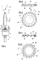
- FIG. 1 shows the essentials for understanding the invention Parts of a common ring spinning spindle 1. It comprises a rotatable spindle upper part 3 mounted in a lower spindle part 2, on which a sleeve 4 is attached.
- the upper spindle part 3 will by a spindle spindle 5, not shown in detail arranged drive, for example in the form of a tangential belt in Rotation offset.
- On the sleeve 4 is by means of a Spinning ring 6 rotating rotor 7 from a thread 8, the a drafting device, not shown, via a thread guide 9 runs, a winding 10 built.
- Sleeve 4 and winding 10 form a cop 11.
- the ring spinning spindle 1 is shown in a position in which after finishing a cop 11 of the spinning ring 6 down guided and in an underwind area 12 of the upper spindle part 3 a winding 13 has been formed. This runs from the winding of the cop 11 a spinning thread 14 for winding 13. This spinning thread 14 must be separated when pulling out a cop become. To facilitate this and pulling thread To prevent from underwinding 13 is between the underwinding area 12 and the cop 11 on the upper spindle part 3 Separating device 15 arranged with a separating knife, on the Cutting edge of the spinning thread 14 is present when the cop is pulled off pressed and cut in the process.
- the separating device 15 is an embodiment variant 2 and 3 of a flat steel disc from the outside edge by means of an in Fig. 3 indicated disc-shaped grinding wheel 16 one after the other sharp cutting edges 17 are ground between them these cutting-edge tabs 19 remain, of which two dashed lines are indicated on the side of the grinding wheel. These tabs 19 are then still in a pulling process bent over at the bottom so that they protrude the cutting edges 17 and one substantial extension in the direction of the axis of the ring spinning spindle Form 1 having cams 18. You pose this way both protection against touching the cutting edges as well Leading edges for the spinning thread.
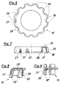
- FIG. 4 and 5 show an embodiment in which the outer edge the steel disc from which the separator 15 is made is, preferably by punching into differently shaped, lobes 19 and 20 indicated by dashed lines at one point is formed, from which on the one hand the cutting edges 17 and on the other hand the cams 18 are formed.
- the separating cut goes 21 between the tabs 19 and 20 up to an imaginary dash-dotted circle 22, from which the cams 18 the plane of the cutting edges 17 are to be bent out.
- the for the Cutting 17 provided tabs 19 are, for example, on the in Fig. 3 indicated way sharpened.
- the one for the cams 18 provided tabs 20 are pulled towards the axis of the ring spinning spindle in the one shown in FIG. 4 Curved up and down.
- the contour of the cams 18 can with this production method by appropriate punching dies can be designed arbitrarily.
- the cams 18 '' can be reached after another Proposal of the invention according to FIG. 8 by bending back their correspondingly longer flaps 20 doubled become. This deformation can also be caused by a pulling process in the direction of the axis of the ring spinning spindle.
- the two Layers of the tabs 20 forming the cams 18 ′′ can be with one another glued, soldered or otherwise firmly connected and to be additionally stiffened.
- the cutting edges 17 'as in FIGS. 6 and 7th together by scraping with a lifting movement Tool are manufactured.
- the cams 18 ′′ are through multiple bending of the tabs 20 formed. As can be seen bending the tabs 20 offers the possibility of the cams to train in various forms. Those lying on one level Cutting edges 17 'of FIG. 9 can also be angled as in FIG. 8 and then lie in the surface of a cone or a cylinder.
- the separating devices of FIGS. 6 to 8 have their inner diameter a collar 28 by means of which the separator is guided exactly on the upper part of the spindle.
- This covenant 28 can be molded on when pulling the separator.
- this collar 28 also have a nose 29 which behind a groove in Upper spindle part 2 occurs and the separating device on the Specifies the upper part of the spindle.
- a separator about a shape as shown in Fig. 6 and 7, can also be achieved by a non-cutting molding process can be achieved in a negative form.
- This can be a pressure or injection molding process or around sintering powder metal act in a corresponding divisible form.
- the Rule are one in this way in one step manufactured separator no further (post) operations required. In some cases it can be advantageous to sharpen the cutting edges 17, 17 '. This offers itself especially a galvanic operation.
Landscapes
- Engineering & Computer Science (AREA)
- Mechanical Engineering (AREA)
- Textile Engineering (AREA)
- Spinning Or Twisting Of Yarns (AREA)
Abstract
In einer weiteren Ausführungsform der Erfindung kann die Trennvorrichtung einschließlich ihrer Schneiden und Nocken als ein in einem spanlosen Fertigungsgang hergestelltes Teil ausgebildet sein.
Description
- Fig. 1
- die Ansicht einer Ringspinnspindel mit Trennvorrichtung;
- Fig. 2
- eine erste Ausbildungsvariante der Erfindung mit einer scheibenförmigen Trennvorrichtung teilweise in Ansicht, teilweise in Schnittdarstellung;
- Fig. 3
- die Draufsicht auf den Gegenstand der Fig. 2;
- Fig. 4 und 5
- eine weitere Ausbildungsvariante der Erfindung in Darstellung wie in den Fig. 2 und 3;
- Fig. 6 und 7
- eine Ausbildungsvariante der Erfindung in Topfform und in Darstellung wie in den Fig. 2 und 3;
- Fig. 8 und 9
- Ausgestaltungen der Erfindung in ausschnittsweiser Schnittdarstellung.
- 1
- Ringspinnspindel
- 2
- Spindelunterteil
- 3
- Spindeloberteil
- 4
- Hülse
- 5
- Spindelbank
- 6
- Spinnring
- 7
- Läufer
- 8
- Faden
- 9
- Fadenführer
- 10
- Wicklung
- 11
- Kops
- 12
- Unterwindebereich
- 13
- Unterwindung
- 14
- Abspinnfaden
- 14'
- Anspinnfaden
- 15, 15'
- Trennvorrichtung
- 16
- Schleifscheibe
- 17, 17'
- Schneiden
- 18, 18', 18''
- Nocken
- 19, 20
- Lappen
- 21
- Trennschnitt
- 22
- Kreis
- 23
- Abstand
- 24
- Vorsprünge
- 25
- Einziehungen
- 26
- Seitenflächen
- 27
- Abgeschabter Bereich
- 28
- Bund
- 29
- Nase
Claims (14)
- Ringspinnspindel mit einer Trennvorrichtung zum Trennen eines Abspinnfadens beim Abziehen eines Kopses, die Schneiden und Nocken umfaßt, wobei die Nocken die Schneiden abschnittsweise radial überragen und sich auch in Richtung der Achse der Ringspinnspindel erstrecken, dadurch gekennzeichnet, daß die Trennvorrichtung (15, 15) aus einem einzigen, zylindrischen oder schwach kegeligen, flach topfförmigen Teil besteht, dessen Rand abschnittweise zu vorkragenden, stumpfkantigen Nocken (18, 18', 18
 ) und zu zurückgesetzten, scharfkantigen Schneiden (17, 17') ausgeformt ist.
- Ringspinnspindel nach Anspruch 1, dadurch gekennzeichnet, daß die Trennvorrichtung (15, 15') ein gezogenes Blechteil ist.
- Ringspinnspindel nach Anspruch 2, dadurch gekennzeichnet, daß in die Außenkante des die Trennvorrichtung (15) bildenden Blechteils voneinander gesonderte Schneiden (17) eingearbeitet und mindestens die zwischen den Schneiden (17) stehen gebliebenen Zähne in Richtung der Achse der Ringspinnspindel (1) gezogen sind und die Nocken (18) bilden. (Fig. 2 und 3)
- Ringspinnspindel nach Anspruch 2, dadurch gekennzeichnet, daß die Außenkante des die Trennvorrichtung (15) bildenden Blechteils in eine Vielzahl von gesonderten Lappen (19, 20) ausgeformt ist, die abwechselnd als Schneiden (17, 17') und als die Schneiden überragende Nocken (18, 18', 18'') ausgebildet und daß mindestens die die Nocken (18) bildenden Lappen (20) in Richtung der Achse der Ringspinnspindel (1) gezogen sind. (Fig. 4 und 5)
- Ringspinnspindel nach Anspruch 3 oder 4, dadurch gekennzeichnet, daß die Nocken (18'') durch Zurückbiegen eines Teilabschnitts der Länge der sie formenden Zungen bzw. Lappen (20) aufgedoppelt sind. (Fig. 8 und 9)
- Ringspinnspindel nach Anspruch 5, dadurch gekennzeichnet, daß zwischen den Innenflächen der Nocken (18) und den Schneiden (17) ein Abstand (23) besteht (Fig. 4)
- Ringspinnspindel nach Anspruch 1, dadurch gekennzeichnet, daß die Nocken (18, 18, 18

- Ringspinnspindel nach Anspruch 1, dadurch gekennzeichnet, daß das die Trennvorrichtung (15') bildende Blechteil zu einem topfförmigen, zylindrischen oder schwach kegeligen Körper mit die Nocken (18') bildenden Vorsprüngen (24) und mit die Schneiden (17') enthaltenden Rücksprüngen (25) gezogen ist. (Fig. 6 und 7)
- Verfahren zum Herstellen der Trennvorrichtung gemäß Anspruch 8, dadurch gekennzeichnet, daß die Wand des topfförmigen Blechteils durch ein Ziehwerkzeug bearbeitet wird, das durch Materialabtragung beim Ziehvorgang in gesonderten Bereichen des Randes dieser Wand zurückgesetzte, scharfkantige Schneiden ausformt.
- Ringspinnspindel nach Anspruch 1, dadurch gekennzeichnet, daß die Trennvorrichtung (15, 15') ein in einem spanlosen Fertigungsgang hergestelltes Teil ist, bei dem mindestens sowohl die Nocken (18, 18', 18'') als auch die Schneiden (17, 17') ausgeformt werden.
- Verfahren zum Herstellen der Ringspinnspindel nach Anspruch 10, dadurch gekennzeichnet, daß der spanlose Fertigungsgang ein Pulvermetall-Sinter- Vorgang ist.
- Verfahren zum Herstellen der Ringspinnspindel nach Anspruch 10, dadurch gekennzeichnet, daß der spanlose Fertigungsgang ein Druck- oder Spritzgußvorgang ist.
- Verfahren zum Herstellen der Ringspinnspindel nach Anspruch 10, dadurch gekennzeichnet, daß die Trennvorrichtung (15, 15') nach dem spanlosen Fertigungsgang einer Nachbehandlung zum Schärfen der Schneiden (17, 17') unterzogen worden ist.
- Verfahren zum Herstellen der Ringspinnspindel nach Anspruch 13, dadurch gekennzeichnet, daß die Nachbehandlung der Trennvorrichtung (15, 15
Applications Claiming Priority (2)
| Application Number | Priority Date | Filing Date | Title |
|---|---|---|---|
| DE19746536 | 1997-10-22 | ||
| DE19746536A DE19746536C2 (de) | 1997-10-22 | 1997-10-22 | Ringspinnspindel mit einem Trennmesser |
Publications (3)
| Publication Number | Publication Date |
|---|---|
| EP0911434A2 true EP0911434A2 (de) | 1999-04-28 |
| EP0911434A3 EP0911434A3 (de) | 2000-07-19 |
| EP0911434B1 EP0911434B1 (de) | 2003-04-09 |
Family
ID=7846211
Family Applications (1)
| Application Number | Title | Priority Date | Filing Date |
|---|---|---|---|
| EP98119832A Expired - Lifetime EP0911434B1 (de) | 1997-10-22 | 1998-10-20 | Ringspinnspindel mit einem Trennmesser |
Country Status (4)
| Country | Link |
|---|---|
| US (1) | US6042045A (de) |
| EP (1) | EP0911434B1 (de) |
| JP (1) | JPH11189936A (de) |
| DE (2) | DE19746536C2 (de) |
Cited By (3)
| Publication number | Priority date | Publication date | Assignee | Title |
|---|---|---|---|---|
| CN102102250A (zh) * | 2009-12-22 | 2011-06-22 | 千田机电有限公司 | 一种细纱机用锭子切纱器 |
| CN103114357A (zh) * | 2013-03-08 | 2013-05-22 | 柳州华晟纺织有限公司 | 光杆锭子割纱器 |
| AT515349A1 (de) * | 2014-01-30 | 2015-08-15 | Electrovac Hacht & Huber Gmbh | Verfahren zur Herstellung eines Anzündersockels |
Families Citing this family (3)
| Publication number | Priority date | Publication date | Assignee | Title |
|---|---|---|---|---|
| CN102296392A (zh) * | 2011-07-25 | 2011-12-28 | 无锡集聚智能纺织机械有限公司 | 适用于机械拔纱的锭子的改进 |
| CH711691A1 (de) | 2015-10-28 | 2017-04-28 | Rieter Ag Maschf | Spindel für eine Arbeitsstelle einer Textilmaschine mit einer Trennvorrichtung. |
| CN116752255B (zh) * | 2023-06-21 | 2026-03-17 | 山西新环精密制造股份有限公司 | 一种纺织设备用夹纱器 |
Family Cites Families (15)
| Publication number | Priority date | Publication date | Assignee | Title |
|---|---|---|---|---|
| JPS5221782Y2 (de) * | 1971-03-29 | 1977-05-19 | ||
| US3731479A (en) * | 1971-10-27 | 1973-05-08 | Springs Mills Inc | Yarn handling apparatus for textile yarn processing machine |
| JPS5094242A (de) * | 1973-12-27 | 1975-07-26 | ||
| US4075919A (en) * | 1973-12-27 | 1978-02-28 | Kabushiki Kaisha Toyoda Jidoshokki Seisakusho | Cutting blade of a device for cutting a yarn in a textile machine |
| JPS5720613Y2 (de) * | 1973-12-27 | 1982-05-04 | ||
| DE7531710U (de) * | 1975-10-06 | 1977-03-31 | Saurer-Allma Gmbh, Allgaeuer Maschinenbau, 8960 Kempten | Spindel mit unterwindkrone fuer ringspinn- und ringzwirnmaschinen, insbesondere fuer cordzwirnmaschinen |
| FR2498637A1 (fr) * | 1981-01-29 | 1982-07-30 | Alsacienne Constr Meca | Procede et dispositif pour la coupe du fil au cours de la levee automatique des bobines sur une machine textile a broches |
| US4796422A (en) * | 1987-05-26 | 1989-01-10 | Odawara Industry Co., Ltd. | Apparatus for treating tail yarn in textile spindle assembly |
| DE4015707A1 (de) * | 1990-05-16 | 1991-11-21 | Zinser Textilmaschinen Gmbh | Fadentrenneinrichtung fuer eine spindel einer spinn- oder zwirnmaschine |
| DE4237475A1 (de) * | 1992-11-06 | 1994-05-11 | Stahlecker Fritz | Vorrichtung zum Durchtrennen eines Fadens bei einer Spinn- oder Zwirnspindel |
| DE4336359A1 (de) * | 1993-10-25 | 1995-04-27 | Zinser Textilmaschinen Gmbh | Fadentrennvorrichtung einer Ringspinn- oder -zwirnspindel |
| JPH08109528A (ja) * | 1994-10-05 | 1996-04-30 | Toyota Autom Loom Works Ltd | 紡機における尻糸切断装置 |
| DE4436790C2 (de) * | 1994-10-14 | 1999-07-29 | Rieter Ag Maschf | Spinnstelle |
| DE4444402A1 (de) * | 1994-12-14 | 1996-06-20 | Rieter Ag Maschf | Spinnstelle zum Herstellen eines Garnwickels |
| DE19537687A1 (de) * | 1995-10-11 | 1997-04-17 | Spindelfabrik Hartha Gmbh | Fadentrenneinrichtung für eine Spindel einer Spinn- oder Zwirnmaschine |
-
1997
- 1997-10-22 DE DE19746536A patent/DE19746536C2/de not_active Expired - Fee Related
-
1998
- 1998-10-20 EP EP98119832A patent/EP0911434B1/de not_active Expired - Lifetime
- 1998-10-20 JP JP10298739A patent/JPH11189936A/ja not_active Withdrawn
- 1998-10-20 DE DE59807834T patent/DE59807834D1/de not_active Expired - Fee Related
- 1998-10-21 US US09/176,165 patent/US6042045A/en not_active Expired - Fee Related
Cited By (6)
| Publication number | Priority date | Publication date | Assignee | Title |
|---|---|---|---|---|
| CN102102250A (zh) * | 2009-12-22 | 2011-06-22 | 千田机电有限公司 | 一种细纱机用锭子切纱器 |
| CN102102250B (zh) * | 2009-12-22 | 2013-09-25 | 千田机电有限公司 | 一种细纱机用锭子切纱器 |
| CN103114357A (zh) * | 2013-03-08 | 2013-05-22 | 柳州华晟纺织有限公司 | 光杆锭子割纱器 |
| CN103114357B (zh) * | 2013-03-08 | 2015-10-07 | 柳州华晟纺织有限公司 | 光杆锭子割纱器 |
| AT515349A1 (de) * | 2014-01-30 | 2015-08-15 | Electrovac Hacht & Huber Gmbh | Verfahren zur Herstellung eines Anzündersockels |
| AT515349B1 (de) * | 2014-01-30 | 2015-11-15 | Electrovac Hacht & Huber Gmbh | Verfahren zur Herstellung eines Anzündersockels |
Also Published As
| Publication number | Publication date |
|---|---|
| EP0911434A3 (de) | 2000-07-19 |
| DE19746536A1 (de) | 1999-04-29 |
| JPH11189936A (ja) | 1999-07-13 |
| US6042045A (en) | 2000-03-28 |
| DE19746536C2 (de) | 2002-08-01 |
| DE59807834D1 (de) | 2003-05-15 |
| EP0911434B1 (de) | 2003-04-09 |
Similar Documents
| Publication | Publication Date | Title |
|---|---|---|
| EP3113894B1 (de) | Werkzeugvorrichtung mit einem bauteil zur herstellung einer formschlüssigen nietverbindung | |
| EP1131012B1 (de) | Wurzelkanalinstrument und verfahren zu dessen herstellung | |
| DE102009018405A1 (de) | Verfahren und Vorrichtung zum Beseitigen eines Sekundärgrates an einem stirnverzahnten Werkstückrad | |
| DE102012201624A1 (de) | Sägeblatt | |
| DE3816963A1 (de) | Stanzwerkzeug | |
| EP3340771B1 (de) | Oszillationsgartengerät, getriebeelement eines oszillationsgartengeräts und verfahren mit einem oszillationsgartengerät | |
| DE102007049057B4 (de) | Einstückig ausgebildeter Messerkopf und Verfahren zum Nachschleifen eines solchen Messerkopfes | |
| DE2461621A1 (de) | Schneidvorrichtung fuer textilmaschinen | |
| DE2820220A1 (de) | Raspelmesser fuer reifen | |
| EP0911434B1 (de) | Ringspinnspindel mit einem Trennmesser | |
| CH676940A5 (de) | ||
| EP0099490B1 (de) | Spanlos geformter Offenend-Spinnrotor sowie Verfahren zur Herstellung eines solchen Offenend-Spinnrotors | |
| DE4122968C2 (de) | Matrizeneinheit | |
| DE379262C (de) | Maschine zum Schlitzen der Koepfe von Schrauben u. dgl. | |
| DE2939325A1 (de) | Aus einem grundkoerper und einem rotorkoerper bestehender offenend-spinnrotor | |
| DE202016102635U1 (de) | Schaftfräser | |
| DE202009005460U1 (de) | Fräswerkzeug zur Bearbeitung von Brillengläsern | |
| WO2018041436A1 (de) | Einschneidiges fräswerkzeug | |
| DE202017103021U1 (de) | Schaftfräser | |
| DE102016109130A1 (de) | Schaftfräser | |
| DE2947806A1 (de) | Verfahren zum herstellen von kolbennadeln fuer naehmaschinen | |
| DE8915215U1 (de) | Vorrichtung zum Herstellen von Profil-Werkstücken, insbesondere Zahnrädern | |
| DE102006021168B4 (de) | Fadentrennvorrichtung und Verfahren zur Herstellung einer Fadentrennvorrichtung | |
| EP1367155A2 (de) | Auflösewalzeneinheit eines Offenend-Spinnaggregats | |
| EP2186591A1 (de) | Messerkopf und Vefahren zum Herstellen eines Messerkopfes |
Legal Events
| Date | Code | Title | Description |
|---|---|---|---|
| PUAI | Public reference made under article 153(3) epc to a published international application that has entered the european phase |
Free format text: ORIGINAL CODE: 0009012 |
|
| AK | Designated contracting states |
Kind code of ref document: A2 Designated state(s): CH DE IT LI |
|
| AX | Request for extension of the european patent |
Free format text: AL;LT;LV;MK;RO;SI |
|
| PUAL | Search report despatched |
Free format text: ORIGINAL CODE: 0009013 |
|
| AK | Designated contracting states |
Kind code of ref document: A3 Designated state(s): AT BE CH CY DE DK ES FI FR GB GR IE IT LI LU MC NL PT SE |
|
| AX | Request for extension of the european patent |
Free format text: AL;LT;LV;MK;RO;SI |
|
| 17P | Request for examination filed |
Effective date: 20000802 |
|
| AKX | Designation fees paid |
Free format text: CH DE IT LI |
|
| GRAH | Despatch of communication of intention to grant a patent |
Free format text: ORIGINAL CODE: EPIDOS IGRA |
|
| GRAH | Despatch of communication of intention to grant a patent |
Free format text: ORIGINAL CODE: EPIDOS IGRA |
|
| GRAA | (expected) grant |
Free format text: ORIGINAL CODE: 0009210 |
|
| AK | Designated contracting states |
Designated state(s): CH DE IT LI |
|
| REG | Reference to a national code |
Ref country code: CH Ref legal event code: EP |
|
| PLBE | No opposition filed within time limit |
Free format text: ORIGINAL CODE: 0009261 |
|
| STAA | Information on the status of an ep patent application or granted ep patent |
Free format text: STATUS: NO OPPOSITION FILED WITHIN TIME LIMIT |
|
| 26N | No opposition filed |
Effective date: 20040112 |
|
| PGFP | Annual fee paid to national office [announced via postgrant information from national office to epo] |
Ref country code: DE Payment date: 20071212 Year of fee payment: 10 |
|
| PG25 | Lapsed in a contracting state [announced via postgrant information from national office to epo] |
Ref country code: DE Free format text: LAPSE BECAUSE OF NON-PAYMENT OF DUE FEES Effective date: 20090501 |
|
| REG | Reference to a national code |
Ref country code: CH Ref legal event code: PUE Owner name: ZHUOLANG TEXTILE MACHINERY CO. LTD., CN Free format text: FORMER OWNER: ZINSER TEXTILMASCHINEN GMBH, DE Ref country code: CH Ref legal event code: NV Representative=s name: SCHMAUDER AND PARTNER AG PATENT- UND MARKENANW, CH |
|
| PGFP | Annual fee paid to national office [announced via postgrant information from national office to epo] |
Ref country code: CH Payment date: 20141022 Year of fee payment: 17 |
|
| PGFP | Annual fee paid to national office [announced via postgrant information from national office to epo] |
Ref country code: IT Payment date: 20141022 Year of fee payment: 17 |
|
| REG | Reference to a national code |
Ref country code: CH Ref legal event code: PL |
|
| PG25 | Lapsed in a contracting state [announced via postgrant information from national office to epo] |
Ref country code: LI Free format text: LAPSE BECAUSE OF NON-PAYMENT OF DUE FEES Effective date: 20151031 Ref country code: IT Free format text: LAPSE BECAUSE OF NON-PAYMENT OF DUE FEES Effective date: 20151020 Ref country code: CH Free format text: LAPSE BECAUSE OF NON-PAYMENT OF DUE FEES Effective date: 20151031 |