EP0911461A1 - Store banne monobloc à toile protégée - Google Patents
Store banne monobloc à toile protégée Download PDFInfo
- Publication number
- EP0911461A1 EP0911461A1 EP98420191A EP98420191A EP0911461A1 EP 0911461 A1 EP0911461 A1 EP 0911461A1 EP 98420191 A EP98420191 A EP 98420191A EP 98420191 A EP98420191 A EP 98420191A EP 0911461 A1 EP0911461 A1 EP 0911461A1
- Authority
- EP
- European Patent Office
- Prior art keywords
- profile
- supports
- console
- monobloc
- arm
- Prior art date
- Legal status (The legal status is an assumption and is not a legal conclusion. Google has not performed a legal analysis and makes no representation as to the accuracy of the status listed.)
- Withdrawn
Links
Images




Classifications
-
- E—FIXED CONSTRUCTIONS
- E04—BUILDING
- E04F—FINISHING WORK ON BUILDINGS, e.g. STAIRS, FLOORS
- E04F10/00—Sunshades, e.g. Florentine blinds or jalousies; Outside screens; Awnings or baldachins
- E04F10/02—Sunshades, e.g. Florentine blinds or jalousies; Outside screens; Awnings or baldachins of flexible canopy materials, e.g. canvas ; Baldachins
- E04F10/06—Sunshades, e.g. Florentine blinds or jalousies; Outside screens; Awnings or baldachins of flexible canopy materials, e.g. canvas ; Baldachins comprising a roller-blind with means for holding the end away from a building
- E04F10/0637—Sunshades, e.g. Florentine blinds or jalousies; Outside screens; Awnings or baldachins of flexible canopy materials, e.g. canvas ; Baldachins comprising a roller-blind with means for holding the end away from a building with mechanisms for adjusting the inclination of the blind
-
- E—FIXED CONSTRUCTIONS
- E04—BUILDING
- E04F—FINISHING WORK ON BUILDINGS, e.g. STAIRS, FLOORS
- E04F10/00—Sunshades, e.g. Florentine blinds or jalousies; Outside screens; Awnings or baldachins
- E04F10/02—Sunshades, e.g. Florentine blinds or jalousies; Outside screens; Awnings or baldachins of flexible canopy materials, e.g. canvas ; Baldachins
- E04F10/06—Sunshades, e.g. Florentine blinds or jalousies; Outside screens; Awnings or baldachins of flexible canopy materials, e.g. canvas ; Baldachins comprising a roller-blind with means for holding the end away from a building
- E04F10/0611—Sunshades, e.g. Florentine blinds or jalousies; Outside screens; Awnings or baldachins of flexible canopy materials, e.g. canvas ; Baldachins comprising a roller-blind with means for holding the end away from a building with articulated arms supporting the movable end of the blind for deployment of the blind
- E04F10/0618—Sunshades, e.g. Florentine blinds or jalousies; Outside screens; Awnings or baldachins of flexible canopy materials, e.g. canvas ; Baldachins comprising a roller-blind with means for holding the end away from a building with articulated arms supporting the movable end of the blind for deployment of the blind whereby the pivot axis of the articulation is perpendicular to the roller
-
- E—FIXED CONSTRUCTIONS
- E04—BUILDING
- E04F—FINISHING WORK ON BUILDINGS, e.g. STAIRS, FLOORS
- E04F10/00—Sunshades, e.g. Florentine blinds or jalousies; Outside screens; Awnings or baldachins
- E04F10/02—Sunshades, e.g. Florentine blinds or jalousies; Outside screens; Awnings or baldachins of flexible canopy materials, e.g. canvas ; Baldachins
- E04F10/06—Sunshades, e.g. Florentine blinds or jalousies; Outside screens; Awnings or baldachins of flexible canopy materials, e.g. canvas ; Baldachins comprising a roller-blind with means for holding the end away from a building
- E04F10/0662—Sunshades, e.g. Florentine blinds or jalousies; Outside screens; Awnings or baldachins of flexible canopy materials, e.g. canvas ; Baldachins comprising a roller-blind with means for holding the end away from a building with arrangements for fastening the blind to the building
-
- E—FIXED CONSTRUCTIONS
- E04—BUILDING
- E04F—FINISHING WORK ON BUILDINGS, e.g. STAIRS, FLOORS
- E04F10/00—Sunshades, e.g. Florentine blinds or jalousies; Outside screens; Awnings or baldachins
- E04F10/02—Sunshades, e.g. Florentine blinds or jalousies; Outside screens; Awnings or baldachins of flexible canopy materials, e.g. canvas ; Baldachins
- E04F10/06—Sunshades, e.g. Florentine blinds or jalousies; Outside screens; Awnings or baldachins of flexible canopy materials, e.g. canvas ; Baldachins comprising a roller-blind with means for holding the end away from a building
- E04F10/0685—Covers or housings for the rolled-up blind
Definitions
- the present invention relates generally the blinds, and its purpose is, more in particular, a blind which belongs to the so-called type "monobloc awning", and also provides protection rolled up canvas.
- the commodity is currently made up of a bar carrier of square, rectangular or more profile section particular, steel or aluminum, on which are fixed the various supports of parts of the blind, especially the arms and roller supports.
- This bar also serves, via fixed consoles against a wall or under a ceiling, connecting element of the store in the building.
- the load-bearing bar must be strong enough to support all couples of bending and torsion generated by the stresses of the wind and bad weather on the awning.
- protective elements such as an awning intended to protect the rolled canvas from rain or snow, or a completely wrapped protective box the rolled up canvas and thus protecting it from all atmospheric pollution. It goes without saying that the addition such protective elements increases significant cost prices and selling prices of blinds concerned.
- Such a store includes an envelope generally made by aluminum profiles, inside which is housed and fixed the entire blind, that is to say, no only the canvas but also the complete frame. We thus obtains complete protection of the blind in position folded up.
- the envelope which serves as a carrying element for the blind, is itself hung on consoles attached to the building. It must be strong enough to bear all the stresses to which is subjected the blind, which means that the constituent profiles of the envelope must be thick and robust, therefore expensive. Cassette blinds made in this way are therefore themselves particularly expensive, and can only constitute high-end products.
- a more economical version of cassette store has a sectional envelope profile in general shape of "C", closed at its ends by two flanges serving to roller support, arm support and fixing bracket to the building.
- This conception in which arms are bound to the ends of the envelope, is limited in its application to blinds with a maximum width of approximately 5 meters, and which have only two arms.
- blind tolerates virtually no imprecision when tracing and laying of the anchors, and its installation can only be carried out by a qualified professional.
- the present invention aims to remedy this situation, by providing a one-piece awning new design allowing, practically without increase in its cost price, to add important additional functions, in particular a full protection of the fabric against bad weather and pollution when the blind is folded, while providing ease and economy of installation and adjustment, the proposed design is also not limited in its applications.
- the invention essentially has for object a monobloc awning, comprising a canvas, a canvas winding tube, load bar, at at least two articulated arms mounted on supports and linked to the load bar, and means for fixing the whole against a wall or under a ceiling
- this blind being characterized in that it also comprises a profile of section in general shape of "C", with slit longitudinal exit of the fabric, intended to wrap fully rolled up canvas, profile supporting the bearings used for the rotary mounting of the tube of winding inside this profile, and said profile being also rigidly linked, both in longitudinal direction that in rotation, to the supports arm, so that this profile constitutes an element for pre-assembly and pre-adjustment of the blind, the assembly being intended to be hung via supports arms to plates or consoles fixed to the wall or under the ceiling.
- the idea behind the invention is to use a profile, completely wrapping the canvas rolled up for full protection, as connecting element of the components of the blind that are bearings supporting the fabric winding tube, on the one hand, and the arms supports, on the other hand.
- the profile thus serves as a pre-assembly and pre-adjustment element awning in the workshop, in addition to its function of canvas protection. No resistance to pressure due to wind is not required from the profile since these pressures result in a bending force on each arm, effort which is taken up by the supports of arms and turntables or consoles; this profile can therefore be of light construction, with a small thickness of material, therefore economical.
- the arms articulated and their supports are positioned externally to the profile, the latter comprising at least a longitudinal groove opening towards the outside, such as a "T" profile groove, allowing a rigid connection of the profile with the arm supports at the by means of screws and nuts, the latter being positioned and immobilized in rotation in the groove.
- the profile also has at least two other grooves longitudinal opening inwards, and provided for fixing the bearings at both ends of the profile ensuring the maintenance of the canvas winding tube.
- each arm support is hung on the plate or corresponding console so that rotate relative to this turntable or console, means being provided for adjusting and fixing the angular position of the arm support relative to the turntable or console.
- the angular adjustment of supports provides tilt adjustment of the arms and awning fabric (in the deployed state), and it comes with a corresponding tilt adjustment of the profile.
- Each plate or console can here include a wing horizontal, projecting forward, the edge of which is planned for hanging, with possibility of pivoting about a horizontal axis, of the arm support corresponding, this support receiving at least one screw pressure pressing on part of the plate or console, a flange being provided at the base of the support arm for locking it on the plate or console in the inclination given by the screw (s) pressure.
- each console includes, between two lateral wings, a transverse rib of which the outer edge is provided for hanging, with possibility of pivoting around a horizontal axis, corresponding arm support, the console bearing in its lower part a screw for adjusting the inclination of the blind, fitted with a cooperating cylindrical flange with a ramp formed in the lower part of the support corresponding arm, this part itself carrying a locking screw with shaped flange cylindrical, which is intended to engage in a complementary recess dug in the rib transverse of the console, said rib having a notch opening on its outer edge, for passage of the locking screw.
- a spring helical is mounted and compressed around the screw adjustment and around the locking screw, under the flange corresponding.
- This latter embodiment turns out particularly advantageous because it allows pre-hanging easy and practically instantaneous of the whole pre-mounted awning, with possibility to adjust later tilt this set and lock everything device, using only two screws for each console.
- This embodiment is also advantageous, in comparison with the previous one, in the sense that it is particularly simple, especially since it is not no more need to bring back an extra piece such as flange for locking.
- each arm support is hooked non-pivotally on the plate or corresponding console, including a double hooking, so that the profile rigidly linked to arm supports is also fixed, means being provided for the tilt adjustment of each arm relative to its support.
- the tilt adjustment of the blind here is different, the profile remains fixed and only the arms being adjustable.
- the blind has a canvas 1, which is fixed at its upper part to a tube 2 with a horizontal axis around which it is wound, and at its lower part on a horizontal load bar 3.
- the fabric 1 is held in tension by two arms articulated 4, symmetrical to each other, each formed an anterior element 5 and a posterior element 6 connected by an intermediate joint 7.
- the end lower of the front arm element 5 is linked to the bar load 3 by an articulation along an axis 8, this articulated connection being made using a groove longitudinal 9 of the profile constituting the load bar 3 (see also Figure 2).
- the upper end of the element posterior arm 6 is linked, along an axis articulation 10, to a support 11 itself provided for hang on a plate or console 12 to fix against a wall 13.
- the blind also includes a horizontal profile in aluminum or other 14, generally in cross-section "C", which is fixed on the two arm supports 11.
- the winding tube 2 of the fabric 1 is rotatably mounted at the interior of the profile 14, by means of two bearings 15 provided at its ends and fixed to said profile 14.
- the winding tube 2 still receives at one end an operating winch 16.
- Two hubcaps 17 serve to close the assembly at the ends of the profile 14.
- the profile 14 has a longitudinal slot 18 limited by a rounded edge 19, for the exit of the canvas 1, and it has two grooves longitudinal "T" spaced 20 and 21 opening towards the interior of this profile 14, as well as a groove longitudinal "T” 22 opening towards the outside of this profile 14.
- the wall part of profile 14 defining externally the groove 20 has an extension 23 in beak shape, which further defines an open groove 24 outwards.
- Each bearing 15, intended for the rotary mounting of the winding tube 2 has three legs 25, 26 and 27 of radial branches, which are respectively hung or fixed in the rounded edge 19 and in the two grooves 20 and 21 of the profile 14, the fixing in these grooves being produced by means of screws 28 and nuts 29, the latter being positioned and immobilized in rotation in the grooves.
- Each arm support 11 has, seen from the side, a form comparable to that of the Greek letter " ⁇ " (tau).
- This profile 14 is fixed on the upper parts of the two supports 11, thus conformed, on the one hand to the level of the groove 22 by means of screws 30 and nuts 31, the latter being positioned and immobilized in rotation in the groove 22, and on the other hand by hooking in the groove 24 bounded by spout 23.
- Each plate 12, essentially vertical, here has a horizontal wing 32, projecting towards the front and limited by a front edge 33 facing the high, with rounded profile.
- the upper part of the support corresponding arm 11 is hung, thanks to a kind of beak 34, on the edge 33 of the wing 32 of the plate 12, the support 11 thus being suspended from the plate 12 of pivoting, following a "hinge" with a horizontal axis.
- each support 11 is drilled with two tapped holes, receiving respectively two pressure screws 36 and 37 which are supported on respective ribs 38 and 39 formed, one under the wing horizontal 32 of plate 12, and the other, at the base of the plate 12. It suffices to screw or unscrew the two pressure screws 36 and 37 to tilt more or minus each support 11, and therefore to orient the whole functional set of the blind, namely the two articulated arms 4, profile 14 and load bar 3 which, in the folded position, closes the slot 18 of the profile 14 (see figure 2).
- the assembly is locked with a lower flange 40 of angled shape, which is on the one hand engaged in a lower groove 41 of the plate 12, delimited by the rib 39, and on the other hand clamped under the support 11 by means of a locking screw 42, the flange 40 having an oblong hole authorizing the passage of the screw 42 in various relative positions, depending on the adjustment made.
- the pressure screws 36 and 37 and the locking screw 42 are socket head screws, similarly features, allowing you to perform all the adjustment and locking with a single key.
- the profile 14 allows pre-assembly of all elements of the blind, to constitute a complete and monobloc whole, preset in workshop if desired, it will suffice to hang on the two plates 12 when the latter will be fixed against the wall 13 by screws 43. It is note that the plates 12 are wider than the arm supports 11, so that the installer is not held to a great precision on the dimensions of lengthwise positioning of the plates 12.
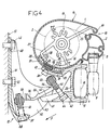
- FIGs 4 to 8 show another form of the monobloc awning object the invention.
- This comprises a profile 14 similar to that of the previous embodiment, still fixed on arm supports 11 which hang on consoles 12 themselves fixed against a wall 13.
- the figure 4 shows the pre-assembled assembly, in the process of hanging on consoles 12, and figure 5 shows this set definitively mounted, while Figures 7 and 8 more particularly illustrate the shapes of a support arms 11 and a console 12.
- Each console 12 comprises, on either side of its rear wall 51 applied against the wall 13, two parallel side wings 52 facing forward and interconnected by an oblique transverse rib 53, including the front edge 54, of rounded shape (in section), is provided for hanging, with the possibility of pivoting along a horizontal axis, of the arm support 11 correspondent.
- the transverse rib 53 of the console 12 has a notch 55, opening on its front edge 54, and a transverse recess 56 with a semi-cylindrical wall, open upwards, which intersects the bottom notch 55.
- Each console 12 also has, at its base, a lower rib 57 which is crossed by a screw adjustment 58 of the tilt of the blind.
- the adjusting screw 58 whose head is supported under the rib 57, bears on its thread a flange 59 of cylindrical shape, playing the nut role.
- a coil spring 60 is mounted and compressed around the adjustment screw 58, between the rib 57 and flange 59.
- the arm support 11 comprises, in its part lower, two parallel wings 61 projecting towards the back, which are connected by a solid part intermediate 62 and which form a ramp 63 facing the top.
- the solid intermediate part 62 is crossed by a locking screw 64, the head of which is supported under this part 62, and the thread of which carries a flange 65 of cylindrical shape, playing the role of a nut, analogous to that mounted on the adjustment screw 58.
- a spring helical 66 is mounted and compressed around the screw lock 64, between the solid part 62 and the flange 65. The latter takes place under the upper part 67 of the arm support 11 which serves as a cradle for the profile 14.
- this form of construction allows quick and easy mounting on consoles 12 previously fixed to the wall 13, of the assembly pre-assembled including profile 14, the two arms articulated 4 and the load bar 3.
- This set is approached the consoles according to arrow F, the wings 61 arm supports 11 being engaged under the ribs 53 of the corresponding 12 consoles, while each flange 65 is engaged above the rib 53 of the corresponding console 12.
- the movement is continued until the flange 65 comes to snap into the recess 56 of the rib 53 of the console 12, the screw locking 64 engaging in the notch 55, while that the ramp 63 of each arm support 11 comes to take support under the flange 59 linked to the console 12, this flange 59 being held in the high position by the spring 60.
- the assembly is locked by tightening the screw locking 64.
- the tightening of this locking screw 64 strongly applies the ramp 63 of the arm support 11 against the flange 59 of the adjustment screw 58, thus preventing movement of the arm support 11 which, moreover, is retained on the anterior edge 54 of the rib 53 of the console 12.
- this embodiment allows a significant transverse clearance, for example of the order of 10 to 20 mm, during the introduction and positioning of the arm support 11 in the console 12.
- This allows a very easy installation of the blind and, added to the oblong lights 68 formed in the wall rear 51 of the console 12 for the passage of the screws fixing it 43 to the wall 13, the arrangement is adapted to compensate for inaccuracies possible when tracing and installing the anchors wall mounting 13.
- the tilt adjustment screw 58 and the lock 64 are advantageously head screws hollow, with the same characteristics, as shown on the Figures 4 and 5, which allows all the adjustment to be made and blocking with one and the same key.
- the heads of these screws 58 and 64 can be concealed by covers (not shown).
- FIG. 6 which corresponds to part of the FIG. 5, illustrates a variant which retains all the features previously described, and in which an additional blind tilt adjustment and in particular profile 14 is provided.
- each support 11 in the upper part 67 of each support 11, are provided several pairs of holes 69, arranged in positions separate angles, preferably regularly spaced apart, for example three pairs of holes 69.
- the screws 30, used for fixing the profile 14, can be optionally introduced into any one of the pairs of holes 69, which allows angular adjustment in correspondence with the positions of these holes, while ensuring a rigid connection between the profile 14 and each support 11, once the screws 30 have been tightened.
- FIG 9 shows yet another embodiment of a one-piece awning according to the invention, carried out according to the same principle but provided a different tilt adjustment system, in which the profile 14 and the winding tube 2 held by this profile 14 are fixed, and only the arms 4 are adjustable in inclination.
- winding tube 2 is mounted rotating in bearings not shown attached to ends of profile 14, the latter always serving of pre-assembly element.
- Profile 14 which always has a section in general shape of "C”, here has only one groove longitudinal 22 open to the outside provided for fixing of this profile 14, by means of screws 30 and nuts 31, on two arm supports 11 themselves hooked to plates or consoles 12 fixed against a wall 13.
- Each support 11 is here fixed; he comes to hang on, by his upper part, on the edge 33 of a horizontal wing 32 of the corresponding plate or console 12, and so similar, by its lower part, on the lower edge 44 of this plate or console 12 which forms a return directed upwards.
- Profile 14, thus fixed on supports 11 themselves fixed, is therefore kept fixed.
- Each arm 4 is adjustable in inclination relative to its fixed support 11, via of a known mechanism allowing pivoting around a horizontal axis 45 and comprising two pressure screws 46 and 47, as well as two locking screws 48 and 49 passing through lights in an arc.
- the load bar 3 is constituted by a large section profile, particularly extended towards the rear at its lower part by a wing 50, which in the folded position of the blind wraps completely arms 4 and their tilt mechanism, in the manner a "cassette" type blind.
Landscapes
- Engineering & Computer Science (AREA)
- Architecture (AREA)
- Civil Engineering (AREA)
- Structural Engineering (AREA)
- Building Awnings And Sunshades (AREA)
Abstract
Description
- soit en fonction de leur valeur commerciale, comme produits d'entrée de gamme, de milieu de gamme ou de haut de gamme ;
- soit selon leurs caractéristiques d'installation : stores indépendants, traditionnels ou monoblocs (définis ci-après) ;
- soit d'après leurs options, telles que protection partielle par un auvent, protection complète de la toile en position repliée, ou protection complète de la toile et du mécanisme en position repliée.
- Les stores dits indépendants possèdent d'une part des supports du rouleau de toile, et d'autre part des supports de bras, sans liaison entre eux.
- Les stores dits traditionnels comportent, à chacune de leurs extrémités, un seul et même support pour le rouleau et pour un bras.
- Les stores dits monoblocs possèdent une barre porteuse, sur laquelle sont montés tous les composants du store.
- Il assure une protection intégrale de la toile, en position repliée et aussi pendant les manipulations de transport et de pose.
- Ce store comporte une facilité et une économie de pose accrues, une seule personne pouvant poser ou déposer un tel store de 5 m x 3 m. De plus, la pose et le réglage du store sont à la portée de l'acheteur final, et ne nécessitent pas le recours à un personnel spécialisé.
- Il est aussi possible de choisir et de changer facilement le positionnement des bras, sur la longueur de store.
- La conception de ce store est économique, en raison d'une réduction de la quantité nécessaire de matière première et d'une simplification des opérations de fabrication, ceci pour des caractéristiques d'utilisation égales ou supérieures à celles des produits actuels, notamment du point de vue de la résistance mécanique.
- Enfin, ce store possède à l'état replié un encombrement réduit, notamment en termes de déport par rapport à la façade, et l'ensemble du store est d'une esthétique sobre et discrète, notamment du fait de la suppression de toute barre porteuse disgracieuse, à fonction purement technique.
- en modifiant les détails de formes, tels que ceux du profilé 14, celui-ci pouvant être réalisé en une ou plusieurs pièces,
- en prévoyant des variantes concernant l'accrochage sur les platines ou consoles 12 ou les réglages d'inclinaison,
- en adaptant les platines ou consoles 12 pour une fixation non plus murale, mais sous plafond,
- en prévoyant, dans une autre variante plus élaborée, un positionnement des bras articulés 4 et de leurs supports 11 à l'intérieur du profilé 14, ce qui impliquerait le perçage du profilé en face de chaque support de bras pour permettre la fixation extérieure de semelles de liaison destinées à s'accrocher sur les platines ou consoles et à reprendre les efforts des bras,
- en appliquant l'invention à une store banne comportant plus de deux bras.
Claims (10)
- Store banne monobloc, comprenant une toile (1), un tube d'enroulement (2) de la toile, une barre de charge (3), au moins deux bras articulés (4) montés sur des supports (11) et liés à la barre de charge (3), et des moyens (12) de fixation de l'ensemble contre un mur (13) ou sous un plafond, caractérisé en ce qu'il comprend encore un profilé (14) de section en forme générale de "C", avec fente longitudinale (18) de sortie de la toile, prévu pour envelopper complètement la toile (1) à l'état enroulé, le profilé (14) supportant les paliers (15) servant au montage rotatif du tube d'enroulement (2) à l'intérieur de ce profilé (14), et ledit profilé (14) étant aussi lié rigidement, aussi bien en direction longitudinale qu'en rotation, aux supports (11) des bras (4), de telle sorte que ce profilé (14) constitue un élément de pré-montage et pré-réglage du store, l'ensemble étant prévu pour être accroché par l'intermédiaire des supports de bras (11) à des platines ou consoles (12) fixées au mur (13) ou sous le plafond.
- Store banne monobloc selon la revendication 1, caractérisé en ce que les bras articulés (4) et leurs supports (11) sont positionnés extérieurement au profilé (14), celui-ci comportant au moins une rainure longitudinale (22) s'ouvrant vers l'extérieur, permettant une liaison rigide du profilé (14) avec les supports de bras (11) au moyen de vis (30) et d'écrous (31), ces derniers étant positionnés et immobilisés en rotation dans la rainure (22).
- Store banne monobloc selon la revendication 2, caractérisé en ce que les supports de bras (11) comportent, pour le passage des vis (30) de fixation du profilé (14), plusieurs trous (69) ménagés dans des positions angulaires distinctes, de préférence régulièrement espacées, pour un réglage angulaire d'inclinaison du profilé (14).
- Store banne monobloc selon la revendication 2 ou 3, caractérisé en ce que le profilé (14) comporte encore au moins deux autres rainures longitudinales (20,21) s'ouvrant vers l'intérieur, et prévues pour la fixation, aux deux extrémités du profilé (14), des paliers (15) assurant le maintien du tube d'enroulement (2) de la toile (1).
- Store banne monobloc selon l'une quelconque des revendications 2 à 4, caractérisé en ce que chaque support de bras (11) est accroché sur la platine ou console (12) correspondante de manière à pouvoir pivoter relativement à cette platine ou console (12), des moyens (36 à 42 ; 53 à 66) étant prévus pour le réglage et la fixation de la position angulaire du support de bras (11) relativement à la platine (12), le réglage angulaire des supports de bras (11) s'accompagnant d'un réglage d'inclinaison correspondant du profilé (14).
- Store banne monobloc selon la revendication 5, caractérisé en ce que chaque platine ou console (12) comporte une aile horizontale (32), faisant saillie vers l'avant, dont le bord antérieur (33) est prévu pour l'accrochage, avec possibilité de pivotement autour d'un axe horizontal, du support de bras (11) correspondant, ce support (11) recevant au moins une vis de pression (36,37) prenant appui sur une partie (38,39) de la platine ou console (12), une bride (40) étant prévue à la base du support de bras (11) pour le verrouillage de celui-ci sur la platine ou console (12) dans l'inclinaison donnée par la ou les vis de pression (36,37).
- Store banne monobloc selon la revendication 5, caractérisé à ce que chaque console (12) comporte, entre deux ailes latérales (52), une nervure transversale (53) dont le bord antérieur (54) est prévu pour l'accrochage, avec possibilité de pivotement autour d'un axe horizontal, du support de bras (11) correspondant, la console (12) portant dans sa partie inférieure (57) une vis de réglage (58) de l'inclinaison du store, munie d'une bride (59) de forme cylindrique coopérant avec une rampe (63) formée dans la partie inférieure (61,62) du support de bras (11) correspondant, cette partie portant elle-même uns vis de verrouillage (64) munie d'une bride (65) de forme cylindrique, qui est prévue pour s'engager dans un évidement complémentaire (56) creusé dans la nervure transversale (53) de la console (12), ladite nervure (53) présentant une encoche (55) débouchant sur son bord antérieur (54), pour le passage de la vis de verrouillage (64).
- Store banne monobloc selon la revendication 7, caractérisé en ce qu'un ressort hélicoïdal (60,66) est monté et comprimé autour de la vis de réglage (58) et autour de la vis de verrouillage (64), sous la bride (59,65) correspondante.
- Store banne monobloc selon l'une quelconque des revendications 2 à 4, caractérisé en ce que chaque support de bras (11) est accroché de manière non pivotante sur la platine ou console correspondante (12), notamment par un double accrochage (en 33 et 44), de sorte que le profilé (14) lié rigidement aux supports de bras (11) est lui aussi fixe, des moyens (45 à 49) étant prévus pour le réglage de chaque bras (4) relativement à son support (11).
- Store banne monobloc selon la revendication 1, caractérisé en ce que les bras articulés (4) et leurs supports (11) sont positionnés à l'intérieur du profilé (14), celui-ci étant percé en face de chaque support de bras (11) pour permettre le passage de semelles de liaison destinées à s'accrocher sur les platines ou consoles (12).
Applications Claiming Priority (4)
| Application Number | Priority Date | Filing Date | Title |
|---|---|---|---|
| FR9713465 | 1997-10-22 | ||
| FR9713465A FR2769935B3 (fr) | 1997-10-22 | 1997-10-22 | Store banne monobloc a toile protegee |
| FR9716549A FR2769936B1 (fr) | 1997-10-22 | 1997-12-19 | Store banne monobloc a toile protegee |
| FR9716549 | 1997-12-19 |
Publications (1)
| Publication Number | Publication Date |
|---|---|
| EP0911461A1 true EP0911461A1 (fr) | 1999-04-28 |
Family
ID=26233896
Family Applications (1)
| Application Number | Title | Priority Date | Filing Date |
|---|---|---|---|
| EP98420191A Withdrawn EP0911461A1 (fr) | 1997-10-22 | 1998-10-19 | Store banne monobloc à toile protégée |
Country Status (2)
| Country | Link |
|---|---|
| EP (1) | EP0911461A1 (fr) |
| FR (1) | FR2769936B1 (fr) |
Cited By (2)
| Publication number | Priority date | Publication date | Assignee | Title |
|---|---|---|---|---|
| EP1548203A3 (fr) * | 2003-12-24 | 2008-04-09 | Leiner GmbH | Store |
| FR2920454A1 (fr) * | 2007-09-05 | 2009-03-06 | Coublanc Stores Soc Responsabi | Store banne mono console. |
Citations (2)
| Publication number | Priority date | Publication date | Assignee | Title |
|---|---|---|---|---|
| US3991805A (en) | 1975-04-05 | 1976-11-16 | Firma Clauss-Markisen | Retractable awning of adjustable angle of inclination |
| EP0500030A1 (fr) | 1991-02-21 | 1992-08-26 | Giovanni Scaffidi | Marquise à manchon |
-
1997
- 1997-12-19 FR FR9716549A patent/FR2769936B1/fr not_active Expired - Fee Related
-
1998
- 1998-10-19 EP EP98420191A patent/EP0911461A1/fr not_active Withdrawn
Patent Citations (2)
| Publication number | Priority date | Publication date | Assignee | Title |
|---|---|---|---|---|
| US3991805A (en) | 1975-04-05 | 1976-11-16 | Firma Clauss-Markisen | Retractable awning of adjustable angle of inclination |
| EP0500030A1 (fr) | 1991-02-21 | 1992-08-26 | Giovanni Scaffidi | Marquise à manchon |
Cited By (3)
| Publication number | Priority date | Publication date | Assignee | Title |
|---|---|---|---|---|
| EP1548203A3 (fr) * | 2003-12-24 | 2008-04-09 | Leiner GmbH | Store |
| FR2920454A1 (fr) * | 2007-09-05 | 2009-03-06 | Coublanc Stores Soc Responsabi | Store banne mono console. |
| WO2009030851A3 (fr) * | 2007-09-05 | 2009-05-22 | Coublanc Stores | Store banne mono console |
Also Published As
| Publication number | Publication date |
|---|---|
| FR2769936A1 (fr) | 1999-04-23 |
| FR2769936B1 (fr) | 1999-12-17 |
Similar Documents
| Publication | Publication Date | Title |
|---|---|---|
| FR2747423A1 (fr) | Dispositif de roulement pour ouvrant coulissant de porte, fenetre ou analogue | |
| EP4155500B1 (fr) | Dispositif de supportage d'un tube d'enroulement de volet roulant dans un coffre de volet roulant, sous-ensemble de montage et installation de protection comprenant un tel dispositif de supportage et méthode d'assemblage associée | |
| FR2662466A1 (fr) | Coulisses pour volet roulant equipees d'elements de guidage escamotables pour autoriser le passage des lames d'un tablier. | |
| EP0911461A1 (fr) | Store banne monobloc à toile protégée | |
| FR2682713A1 (fr) | Dispositif de reglage angulaire pour bras articule de store a rouleau ou similaire. | |
| EP0764749A1 (fr) | Dispositif de support d'un élément en porte à faux vis-à-vis de la façade verticale d'un mur rideau d'un batiment ou construction analogue | |
| BE1008714A7 (fr) | Store a caisson. | |
| FR2759402A1 (fr) | Store coffre autoportant monobloc de faible encombrement equipe d'un dispositif de fixation au mur par support independant et d'un systeme de reglage precis de la pente du store | |
| FR2769935A1 (fr) | Store banne monobloc a toile protegee | |
| EP2816189B1 (fr) | Dispositif de correction de la flèche verticale d'une traverse supérieure de la menuiserie d'un système de fermeture | |
| EP0671525A1 (fr) | Store à carcasse enveloppante | |
| FR2709322A1 (fr) | Auvent enroulable. | |
| EP0434545B1 (fr) | Banne comprenant un auvent de protection de l'avancée | |
| FR2474084A1 (fr) | Dispositif a store suspendu et enrouleur pour la realisation d'une marquise | |
| EP2199486A1 (fr) | Store banne, du genre à coffre | |
| EP4400688B1 (fr) | Verrou de volet roulant et installation associée | |
| EP1262627B1 (fr) | Joue support de volet roulant | |
| EP0841461B1 (fr) | Dispositif de montage d'un panneau coulissant | |
| FR2788555A1 (fr) | Ensemble bloc, porte, fenetre ou analogue-volet roulant | |
| FR2820381A1 (fr) | Dispositif pour le transport d'au moins un objet transversalement a l'arriere d'un vehicule automobile | |
| FR2774124A1 (fr) | Tablier de volet roulant ou similaire | |
| FR2782103A1 (fr) | Dispositif d'ombrage et/ou d'occultation a membrane souple | |
| EP0676514A1 (fr) | Dispositif d'ombrage et/ou d'occultation à membrane souple | |
| FR2755714A1 (fr) | Store a auvent reglable en inclinaison | |
| FR3085628A1 (fr) | Dispositif pare-soleil pour garniture de portiere de vehicule automobile |
Legal Events
| Date | Code | Title | Description |
|---|---|---|---|
| PUAI | Public reference made under article 153(3) epc to a published international application that has entered the european phase |
Free format text: ORIGINAL CODE: 0009012 |
|
| AK | Designated contracting states |
Kind code of ref document: A1 Designated state(s): AT BE CH DE DK ES GB GR IT LI MC NL PT SE |
|
| AX | Request for extension of the european patent |
Free format text: AL;LT;LV;MK;RO;SI |
|
| 17P | Request for examination filed |
Effective date: 19990920 |
|
| AKX | Designation fees paid |
Free format text: AT BE CH DE DK ES FR GB GR IT LI MC NL PT SE |
|
| RBV | Designated contracting states (corrected) |
Designated state(s): AT BE CH DE DK ES GB GR IT LI MC NL PT SE |
|
| 17Q | First examination report despatched |
Effective date: 20020205 |
|
| GRAH | Despatch of communication of intention to grant a patent |
Free format text: ORIGINAL CODE: EPIDOS IGRA |
|
| STAA | Information on the status of an ep patent application or granted ep patent |
Free format text: STATUS: THE APPLICATION IS DEEMED TO BE WITHDRAWN |
|
| 18D | Application deemed to be withdrawn |
Effective date: 20030325 |