EP0911617B1 - Procédé pour peser des éclats ou de la poudre - Google Patents
Procédé pour peser des éclats ou de la poudre Download PDFInfo
- Publication number
- EP0911617B1 EP0911617B1 EP98119527A EP98119527A EP0911617B1 EP 0911617 B1 EP0911617 B1 EP 0911617B1 EP 98119527 A EP98119527 A EP 98119527A EP 98119527 A EP98119527 A EP 98119527A EP 0911617 B1 EP0911617 B1 EP 0911617B1
- Authority
- EP
- European Patent Office
- Prior art keywords
- weighing
- conduit
- powder
- chip
- chips
- Prior art date
- Legal status (The legal status is an assumption and is not a legal conclusion. Google has not performed a legal analysis and makes no representation as to the accuracy of the status listed.)
- Expired - Lifetime
Links
Images


Classifications
-
- G—PHYSICS
- G01—MEASURING; TESTING
- G01G—WEIGHING
- G01G13/00—Weighing apparatus with automatic feed or discharge for weighing-out batches of material
- G01G13/02—Means for automatically loading weigh pans or other receptacles, e.g. disposable containers, under control of the weighing mechanism
- G01G13/04—Means for automatically loading weigh pans or other receptacles, e.g. disposable containers, under control of the weighing mechanism involving dribble-feed means controlled by the weighing mechanism to top up the receptacle to the target weight
-
- G—PHYSICS
- G01—MEASURING; TESTING
- G01G—WEIGHING
- G01G13/00—Weighing apparatus with automatic feed or discharge for weighing-out batches of material
- G01G13/02—Means for automatically loading weigh pans or other receptacles, e.g. disposable containers, under control of the weighing mechanism
- G01G13/04—Means for automatically loading weigh pans or other receptacles, e.g. disposable containers, under control of the weighing mechanism involving dribble-feed means controlled by the weighing mechanism to top up the receptacle to the target weight
- G01G13/06—Means for automatically loading weigh pans or other receptacles, e.g. disposable containers, under control of the weighing mechanism involving dribble-feed means controlled by the weighing mechanism to top up the receptacle to the target weight wherein the main feed is effected by gravity from a hopper or chute
Definitions
- This invention relates to a method of weighing powder/chip and, more particularly, it relates to a method of feeding powder/chip to a weighing vessel efficiently and accurately.
- the conduit is tilted with the open end facing downward to dump a large volume of grains from the conduit at a time.
- the volume of grains discharged from the conduit by a single dumping motion varies depending on the state of the conduit and that of the object to be dumped and this variation in the dumped volume inevitably affects the subsequent vibration step of discharging the residual grains to give rise to fluctuations in the weighing accuracy and the weighing speed.
- the step of discharging the residual grains by vibration is apt to be affected by external factors including ambient temperature and humidity to make the fluctuations in the weighing accuracy and the weighing speed even more remarkable, causing problems in efficiency and accuracy.
- a supply device for a weighing equipment and method is known (DE-U 88 01 400.2) supplying weighing goods on filling scales, especially on part amount-combination filling scales comprising a feeding mechanism for transferring the weighing goods from a storage bin to a central distributor mostly in the form of a vibrator conveyor, said distributor being connected with some dosing chutes which transfer the goods into precontainers and following a call to the proper weighing vessels.
- the weighing vessels are combined with electric weighing cells, the measuring results of which are transmitted to a central calculating unit from where the signal for opening the proper weighing vessels into a funnel is given to all those weighing vessels, the total weight of which is coming closest to the predetermined weight striven for.
- this known supply device for part amount-combination filling scales there is combined the drawback that they are rather complicated and that damageable articles, namely thin cookies, filled candies and similar articles can be damaged during their transport between the different places.
- the object of the present invention to provide a method of weighing powder/chip that can feed the powder/chip from the conduit into the weighing vessel accurately and efficiently without being affected by the state of the conduit, that of the weighing vessel and that of the ambient air.
- the above object is achieved by providing a method of weighing powder/chip by means of a conduit arranged below a storage section and adapted to be tilted around a pivot according to a command sent from a weighing section to let the powder/chip fall through a discharge port at an end of the conduit into a weighing vessel placed on the weighing section, the conduit being tilted sequentially by at least three different feeding angles so as to decrease the feeding angle of said conduit (3) to let the powder/chip fall by at least three decreasing regulated volumes.
- the feeding angle of the conduit is set each time to let the powder/chip fall into the weighing vessel after turning the conduit back to the state where the discharge port is facing slightly upwardly of the horizontal state.
- the powder/chip can be fallen to be fed more efficiently with higher weighing precision.
- the feeding angle of the conduit at the final stage is between 1 and 2 degrees from the level position and the discharge port at an end of the conduit is pivoted back and forth between the feeding angle and the level position to let the powder/chip fall into the weighing vessel, so that the weighing precision further improves.
- the method of weighing powder/chip according to the invention can be used for weighing various different powdery and chip-like objects.
- the accompanying drawings show a weighing apparatus to be used with the method of weighing powder/chip according to the invention and adapted to weigh blank chips to be used for molding plastic fasteners.
- FIGS. 1 and 2 show the entire weighing apparatus in which a storage section 1 such as a hopper or a cyclone is arranged at an upper position and contains chips 2 (shown in FIGS. 3 to 7) which are fed via a conduit 3 to a weighing vessel 4 arranged at a lower position for weighing.
- a storage section 1 such as a hopper or a cyclone
- chips 2 shown in FIGS. 3 to 7
- the storage section 1 typically comprises a hopper or a cyclone of an ordinary type having a funnel-shaped bottom portion 5 whose front end is inserted into central opening 6 of the conduit 3 for feeding powder/chip by a predetermined volume.
- the conduit 3 has a box-like profile and the central opening 6 at the top.
- the opposite ends 7, 8 of the conduit 3 are tapered from above and below and one end 7 of the conduit 3 is closed while a discharge port 9 is formed at the opposite end 8 so that chips 2 fall through the discharge port 9 as the conduit 3 is tilted.
- the conduit 3 is supported by a shaft 10 at the center of a lateral side thereof so that the conduit 3 is tilted in a manner as indicated by broken lines in FIG. 2 as the shaft 10 is driven to rotate by a motor 11 connected to the opposite end of the shaft 10.
- the powder/chip contained in the conduit 3 is caused to fall into the weighing vessel 4 as the conduit 3 is tilted to make the discharge port 9 face downward.
- the tilt angle of the conduit 3 can be controlled finely to improve the weighing accuracy by using a stepping motor, a servo motor or the like provided with fine angular control means which enables fine angular indexing for the motor 11.
- the conduit 3 may provided with a bracket at the center of the lateral side so that it may be supported by the shaft 10 by way of the bracket. Additionally, the conduit 3 may be provided with an angle of repose 12 at the center of the bottom thereof to ensure that chips 2 would not fall through the discharge port 9 so long as the conduit 3 is held to a horizontal state.
- the weighing vessel 4 is located below the storage section 1 and the conduit 3 to receive chips 2 discharged from the conduit 3. It is carried by a weighing section 13, which may be a scale, a spring balance or an electronic scale.
- the weighing section 13 measures the weight of the chips 2 fed into the weighing vessel 4 for each of at least three stages and the data obtained by the measurement is fed to central processing unit (CPU) 14, which issues a command to the motor 11 for tilting the conduit 3 according to a computer program to tilt the conduit 3 by a predetermined angle so that the feeding operation may be successively conducted in at least three stages of feeding chips 2 by a large volume, a medium volume and/or a small volume and a minute volume in order to feed the weighing vessel 4 with chips 2 efficiently and accurately.
- CPU central processing unit
- FIGS. 3 through 7 are schematic cross sectional views of the conduit 3 of a weighing apparatus using the weighing method according to the invention held to different tilted positions for feeding chips 2 by a large volume, a medium volume, a small volume and a minute volume respectively.
- FIG. 3 is a schematic cross sectional view of the conduit 3 of the weighing apparatus using the weighing method according to the invention before the start of a weighing operation and filled with chips 2 fed from the storage section 1. Note that chips 2 are fed into the conduit 3 with the discharge port 9 turned upward from the horizontal position and therefore the chips 2 in the conduit 3 are found mostly in the rear portion of the conduit 3. The supply of chips 2 is suspended when the top of the chips 2 in the conduit 3 gets to the bottom portion 5 of the storage section 1.
- the tilted state of the conduit 3 with the discharge port 9 slightly turned upward provides a reference position for the weighing operation of the weighing apparatus and the conduit 3 is turned back to this reference position after each stage of chip discharging operation to receive chips 2 to be in the same condition as that of before the discharging operation and get into the next stage of operation so that an accurately predetermined volume of chips 2 may always be discharged by each chip discharging motion.
- FIG. 4 is a schematic cross sectional view of the conduit 3 same as that of FIG. 3 but held to a tilted position for letting the object of weighing fall by a large volume.
- the conduit 3 is tilted by an inclination angle from the level position for feeding with the discharge port 9 facing downward (hereinafter referred to as the angle of inclination or feeding angle) which is the largest. If a 1,000g of chips is to be weighed in by a single weighing cycle, the conduit 3 is typically tilted by about 30 degrees to discharge about 700g in the first stage.
- FIG. 5 is a schematic cross sectional view of the conduit 3 same as that of FIG. 3 but held to a tilted position with the medium angle of inclination for letting the object of weighing fall by a medium volume.
- the conduit 3 is typically tilted by about 20 degrees to discharge about 230g in the second stage.
- a signal is transmitted to the central processing unit 14 to drive the motor 11 reversely and stop the discharge of the chips 2 and the conduit 3 is turned back again to the reference position indicated by the broken lines.
- the chips 2 are fed in the conduit 3 until it reaches to the amount it had before the dumping operation, as shown in FIG. 3. Then, the operation gets into the third stage of feeding chips by a small volume.
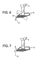
- FIG. 6 is a schematic cross sectional view of the conduit 3 same as that of FIG. 3 but held to a tilted position with the small angle of inclination for letting the object of weighing fall by a small volume.
- the conduit 3 is typically tilted by about 18 degrees to discharge about 64g in the third stage.
- the chips 2 dumped into the weighing vessel 4 gets to 64g to make the total of 994g as sensed by the weighing section 13, a signal is transmitted to the central processing unit 14 to drive the motor 11 reversely and stop the discharge of chips 2 and the conduit 3 is turned back again to the reference position indicated by the broken lines.
- the chips 2 are fed in the conduit 3 until it reaches to the amount it had before the dumping operation, as shown in FIG. 3. Then, the operation gets into the fourth stage of feeding chips 2 by a minute volume. There may arise a situation where the predetermined volume of chips 2 has not been dumped into the weighing vessel 4 within a predetermined period of time with a small angle of inclination. If such is the case, the angle of inclination is automatically increased to let chips 2 fall by the predetermined volume.
- FIG. 7 is a schematic cross sectional view of the conduit 3 same as that of FIG. 3 but held to a tilted position with the minute angle of inclination for letting the object of weighing fall by a minute volume.
- the discharge port 9 is made to swing vertically within an angle of 1 degree from the level position so that the chips 2 in the conduit 3 may be dumped into the weighing vessel 4.
- the conduit 3 is turned back the reference position with the discharge port 9 turning slightly upward so as to stop the dumping.
- the angle of inclination is increased from 1 degree to about 2 degrees so that the chips 2 in the weighing vessel 4 gets to the target volume.
- the chip weighing cycle may alternatively have three stages by omitting the stage of medium volume or that of small volume depending on the target volume of chips to be dumped into the weighing vessel 4.
- the angle of inclination of the conduit 3 for each stage may be modified depending on the target volume of chips to be dumped into the weighing vessel 4.
- the conduit 3 is tilted sequentially at least by three different feeding angles of large, medium or small and minute to let the powder/chip fall through the discharge port 9 by a large volume, a medium or small volume and a minute volume respectively.
- the angle of inclination can be regulated for each stage depending on the state of the conduit 3, that of the object to be discharged, ambient temperature and humidity and other factors.
- the target volume of the powder/chip can be accurately weighed in at the end of the final stage of feeding the powder/chip by a minute volume and fed to the weighing vessel 4. Therefore, with the method of weighing the powder/chip according to the invention, the fluctuation of time required for weighing does not occur, so that the power/chip can be fed to the weighing vessel 4 efficiently, maintaining high weighing precision.
- the feeding angle of the conduit 3 is selected each time to let the powder/chip fall into the weighing vessel 4 after turning the conduit 3 back to the state where the discharge port 9 is facing upwardly of the level position.
- the feeding angle of the conduit 3 at the final stage is between 1 and 2 degrees from the level position and the discharge port 9 at an end of the conduit 3 is pivoted back and forth between the feeding angle and the level position to let the powder/chip fall into the weighing vessel 4.
- the powder/chip can be discharged one by one so that the weighing precision further improves.
Landscapes
- Physics & Mathematics (AREA)
- General Physics & Mathematics (AREA)
- Weight Measurement For Supplying Or Discharging Of Specified Amounts Of Material (AREA)
- Filling Or Emptying Of Bunkers, Hoppers, And Tanks (AREA)
- Processing And Handling Of Plastics And Other Materials For Molding In General (AREA)
Claims (3)
- Procédé de pesage de poudre/granulés au moyen d'un conduit (3) agencé sous une section de stockage (1) et apte à être basculé autour d'un pivot selon un ordre envoyé à la section de pesage (13) afin de faire tomber la poudre/granulés en passant par un orifice d'évacuation (9) situé à une extrémité du conduit (3) jusque dans un récipient de pesage (4) mis en place sur la section de pesage (13), caractérisé en ce que ledit conduit (3) est basculé séquentiellement sous au moins trois angles d'alimentation différents de manière à faire diminuer l'angle d'alimentation dudit conduit (3) de façon à faire tomber la poudre/granulés en au moins trois volumes de croissants régulés.
- Procédé de pesage de poudre/granulés selon la revendication 1, caractérisé en ce que l'angle d'alimentation du conduit (3) est fixé chaque fois de façon à faire tomber la poudre/granulés dans le récipient de pesage (4) après avoir fait tourner le conduit (3) en le ramenant à l'état dans lequel l'orifice d'évacuation (9) est orienté légèrement vers le haut par rapport à l'état horizontal.
- Procédé de pesage de poudre/granulés selon la revendication 1 ou 2, caractérisé en ce que l'angle d'alimentation du conduit (3) au stade final est compris entre 1 et 2 degrés par rapport à la position de niveau et en ce que l'orifice d'évacuation (9) situé à une extrémité du conduit (3) est mis en pivotement en va-et-vient entre l'angle d'alimentation et la position de niveau en vue de faire tomber la poudre/granulés dans le récipient de pesage (4).
Applications Claiming Priority (3)
| Application Number | Priority Date | Filing Date | Title |
|---|---|---|---|
| JP332275/97 | 1997-10-27 | ||
| JP33227597 | 1997-10-27 | ||
| JP33227597A JP3528119B2 (ja) | 1997-10-27 | 1997-10-27 | 粉粒体の計量方法 |
Publications (2)
| Publication Number | Publication Date |
|---|---|
| EP0911617A1 EP0911617A1 (fr) | 1999-04-28 |
| EP0911617B1 true EP0911617B1 (fr) | 2003-07-09 |
Family
ID=18253131
Family Applications (1)
| Application Number | Title | Priority Date | Filing Date |
|---|---|---|---|
| EP98119527A Expired - Lifetime EP0911617B1 (fr) | 1997-10-27 | 1998-10-15 | Procédé pour peser des éclats ou de la poudre |
Country Status (8)
| Country | Link |
|---|---|
| US (1) | US6091028A (fr) |
| EP (1) | EP0911617B1 (fr) |
| JP (1) | JP3528119B2 (fr) |
| KR (1) | KR100284171B1 (fr) |
| CN (1) | CN1120353C (fr) |
| DE (1) | DE69816223T2 (fr) |
| ES (1) | ES2202713T3 (fr) |
| TW (1) | TW360781B (fr) |
Families Citing this family (8)
| Publication number | Priority date | Publication date | Assignee | Title |
|---|---|---|---|---|
| US6502013B1 (en) * | 2000-03-08 | 2002-12-31 | Al Pinhas Sosnik | Method and apparatus for filling containers with a target weight of product |
| ITVR20020101A1 (it) * | 2002-10-16 | 2004-04-17 | Moretto Plastics Automation S R L | Metodo e dispositivo di dosaggio e/o additivazione ad |
| US6959664B1 (en) * | 2003-04-21 | 2005-11-01 | Karl Keuter | Limited flow feeding tube |
| NZ550472A (en) * | 2006-10-11 | 2009-03-31 | Durapod Systems Ltd | Dispensing apparatus |
| JP2013006669A (ja) * | 2011-06-24 | 2013-01-10 | Murata Machinery Ltd | 給糸ボビン供給装置及び給糸ボビン供給装置の制御方法 |
| EP2969485B1 (fr) * | 2013-03-15 | 2019-06-05 | 3D Systems, Inc. | Glissière pour systèmes de frittage laser |
| CN109939753B (zh) * | 2019-04-04 | 2021-01-26 | 河海大学 | 一种用于辅助称量粉末药品的仪器及使用方法 |
| CN113819983B (zh) * | 2021-10-21 | 2023-12-22 | 安徽天膜科技有限公司 | 一种水溶肥防结块剂用精度可调的添加装置 |
Family Cites Families (10)
| Publication number | Priority date | Publication date | Assignee | Title |
|---|---|---|---|---|
| FR2041014B1 (fr) * | 1969-04-30 | 1974-06-14 | Commissariat Energie Atomique | |
| NL166664C (nl) * | 1970-09-14 | 1981-09-15 | Koninklijke Hoogovens En Staal | Inrichting voor het homogeniseren van stortgoed. |
| US3796349A (en) * | 1972-05-18 | 1974-03-12 | R Weber | Weighing dispenser |
| CH563574A5 (fr) * | 1972-11-13 | 1975-06-30 | Electrotechnic & Chemical Engi | |
| JPS5522178A (en) * | 1978-08-07 | 1980-02-16 | Ionii Kk | Grain meter |
| DE3226654A1 (de) * | 1982-07-16 | 1984-01-19 | Focke & Co, 2810 Verden | Vorrichtung und verfahren zur bildung von tabak-portionen |
| DE3880376T2 (de) * | 1987-06-08 | 1993-10-21 | Ngk Insulators Ltd | Apparat zum Wiegen von pulvrigem Material. |
| DE8801400U1 (de) * | 1988-02-04 | 1988-04-07 | Multipond Wägetechnik GmbH, 8264 Waldkraiburg | Zuführeinrichtung für Wägegüter an Abfüllwaagen |
| GB8822109D0 (en) * | 1988-09-20 | 1988-10-19 | Kendall T D | Filling containers |
| DE59005513D1 (de) * | 1989-03-17 | 1994-06-01 | Buehler Ag | Drehgefässwaage. |
-
1997
- 1997-10-27 JP JP33227597A patent/JP3528119B2/ja not_active Expired - Fee Related
-
1998
- 1998-10-13 TW TW087116970A patent/TW360781B/zh not_active IP Right Cessation
- 1998-10-15 ES ES98119527T patent/ES2202713T3/es not_active Expired - Lifetime
- 1998-10-15 DE DE69816223T patent/DE69816223T2/de not_active Expired - Lifetime
- 1998-10-15 EP EP98119527A patent/EP0911617B1/fr not_active Expired - Lifetime
- 1998-10-22 US US09/176,753 patent/US6091028A/en not_active Expired - Fee Related
- 1998-10-26 KR KR1019980044812A patent/KR100284171B1/ko not_active Expired - Fee Related
- 1998-10-27 CN CN98121424A patent/CN1120353C/zh not_active Expired - Lifetime
Also Published As
| Publication number | Publication date |
|---|---|
| JP3528119B2 (ja) | 2004-05-17 |
| ES2202713T3 (es) | 2004-04-01 |
| DE69816223T2 (de) | 2004-05-27 |
| DE69816223D1 (de) | 2003-08-14 |
| KR100284171B1 (ko) | 2001-03-02 |
| TW360781B (en) | 1999-06-11 |
| US6091028A (en) | 2000-07-18 |
| EP0911617A1 (fr) | 1999-04-28 |
| CN1216367A (zh) | 1999-05-12 |
| HK1019481A1 (en) | 2000-02-11 |
| JPH11132834A (ja) | 1999-05-21 |
| KR19990037375A (ko) | 1999-05-25 |
| CN1120353C (zh) | 2003-09-03 |
Similar Documents
| Publication | Publication Date | Title |
|---|---|---|
| US4629017A (en) | Apparatus and method for producing weighed batches of aligned elongated articles | |
| JP2779937B2 (ja) | 重量式計量充填包装機 | |
| US4753306A (en) | Combination weighing method and apparatus using multi-bin scales | |
| US5894111A (en) | Quantitative charging apparatus | |
| US4515231A (en) | Combinatorial weighing apparatus with serial weighing operations | |
| WO2003036243A1 (fr) | Dispositif pour peser des materiaux pulverulents et granuleux | |
| US6091028A (en) | Powder/chip weighing method | |
| JPH02657Y2 (fr) | ||
| EP1424542B1 (fr) | Dispositif de pesage combinatoire | |
| US6905030B2 (en) | Tilting platform checkweighing method | |
| US2191711A (en) | Weighing apparatus | |
| CN215984820U (zh) | 含不及格重量剔除装置的组合秤 | |
| JPS62273413A (ja) | 計量包装装置及びその製品充填高さ測定方法 | |
| JPS6191520A (ja) | 計量充填制御方法およびその装置 | |
| JPH08192802A (ja) | 粉粒体の容器への充填方法及び装置 | |
| JP3406662B2 (ja) | 自動計量装置 | |
| HK1019481B (en) | Powder/chip weighing method | |
| CN221367686U (zh) | 一种输送带分料式组合秤 | |
| ATE71722T1 (de) | Zufuehreinrichtung fuer waegegueter an abfuellwaagen. | |
| JP4601930B2 (ja) | 計量装置および零点調整方法 | |
| JPH05143808A (ja) | 物品収集装置 | |
| JP4686007B2 (ja) | 組合せ計量装置 | |
| JPS5963525A (ja) | 組合せ計量装置における分散供給装置 | |
| JPH067022U (ja) | 細径棒体の計量装置およびそれに使用される整列機構 | |
| JPH0474653B2 (fr) |
Legal Events
| Date | Code | Title | Description |
|---|---|---|---|
| PUAI | Public reference made under article 153(3) epc to a published international application that has entered the european phase |
Free format text: ORIGINAL CODE: 0009012 |
|
| AK | Designated contracting states |
Kind code of ref document: A1 Designated state(s): DE ES FR GB IT |
|
| AX | Request for extension of the european patent |
Free format text: AL;LT;LV;MK;RO;SI |
|
| 17P | Request for examination filed |
Effective date: 19990805 |
|
| AKX | Designation fees paid |
Free format text: DE ES FR GB IT |
|
| 17Q | First examination report despatched |
Effective date: 20020712 |
|
| GRAH | Despatch of communication of intention to grant a patent |
Free format text: ORIGINAL CODE: EPIDOS IGRA |
|
| GRAH | Despatch of communication of intention to grant a patent |
Free format text: ORIGINAL CODE: EPIDOS IGRA |
|
| GRAA | (expected) grant |
Free format text: ORIGINAL CODE: 0009210 |
|
| AK | Designated contracting states |
Designated state(s): DE ES FR GB IT |
|
| REG | Reference to a national code |
Ref country code: GB Ref legal event code: FG4D |
|
| REF | Corresponds to: |
Ref document number: 69816223 Country of ref document: DE Date of ref document: 20030814 Kind code of ref document: P |
|
| REG | Reference to a national code |
Ref country code: ES Ref legal event code: FG2A Ref document number: 2202713 Country of ref document: ES Kind code of ref document: T3 |
|
| ET | Fr: translation filed | ||
| PLBE | No opposition filed within time limit |
Free format text: ORIGINAL CODE: 0009261 |
|
| STAA | Information on the status of an ep patent application or granted ep patent |
Free format text: STATUS: NO OPPOSITION FILED WITHIN TIME LIMIT |
|
| 26N | No opposition filed |
Effective date: 20040414 |
|
| PGFP | Annual fee paid to national office [announced via postgrant information from national office to epo] |
Ref country code: FR Payment date: 20101020 Year of fee payment: 13 |
|
| PGFP | Annual fee paid to national office [announced via postgrant information from national office to epo] |
Ref country code: DE Payment date: 20101013 Year of fee payment: 13 |
|
| PGFP | Annual fee paid to national office [announced via postgrant information from national office to epo] |
Ref country code: GB Payment date: 20101013 Year of fee payment: 13 Ref country code: IT Payment date: 20101018 Year of fee payment: 13 |
|
| PGFP | Annual fee paid to national office [announced via postgrant information from national office to epo] |
Ref country code: ES Payment date: 20101026 Year of fee payment: 13 |
|
| GBPC | Gb: european patent ceased through non-payment of renewal fee |
Effective date: 20111015 |
|
| REG | Reference to a national code |
Ref country code: FR Ref legal event code: ST Effective date: 20120629 |
|
| PG25 | Lapsed in a contracting state [announced via postgrant information from national office to epo] |
Ref country code: DE Free format text: LAPSE BECAUSE OF NON-PAYMENT OF DUE FEES Effective date: 20120501 |
|
| REG | Reference to a national code |
Ref country code: DE Ref legal event code: R119 Ref document number: 69816223 Country of ref document: DE Effective date: 20120501 |
|
| PG25 | Lapsed in a contracting state [announced via postgrant information from national office to epo] |
Ref country code: IT Free format text: LAPSE BECAUSE OF NON-PAYMENT OF DUE FEES Effective date: 20111015 Ref country code: FR Free format text: LAPSE BECAUSE OF NON-PAYMENT OF DUE FEES Effective date: 20111102 Ref country code: GB Free format text: LAPSE BECAUSE OF NON-PAYMENT OF DUE FEES Effective date: 20111015 |
|
| REG | Reference to a national code |
Ref country code: ES Ref legal event code: FD2A Effective date: 20130417 |
|
| PG25 | Lapsed in a contracting state [announced via postgrant information from national office to epo] |
Ref country code: ES Free format text: LAPSE BECAUSE OF NON-PAYMENT OF DUE FEES Effective date: 20111016 |