EP0911956A2 - Appareil de modulation à largeur d'impulsion échelonnée et méthode de minimisation des interférences électromagnétiques dans les moteurs - Google Patents
Appareil de modulation à largeur d'impulsion échelonnée et méthode de minimisation des interférences électromagnétiques dans les moteurs Download PDFInfo
- Publication number
- EP0911956A2 EP0911956A2 EP98119805A EP98119805A EP0911956A2 EP 0911956 A2 EP0911956 A2 EP 0911956A2 EP 98119805 A EP98119805 A EP 98119805A EP 98119805 A EP98119805 A EP 98119805A EP 0911956 A2 EP0911956 A2 EP 0911956A2
- Authority
- EP
- European Patent Office
- Prior art keywords
- motor
- pulsed signal
- winding
- driving
- current
- Prior art date
- Legal status (The legal status is an assumption and is not a legal conclusion. Google has not performed a legal analysis and makes no representation as to the accuracy of the status listed.)
- Withdrawn
Links
Images


Classifications
-
- H—ELECTRICITY
- H02—GENERATION; CONVERSION OR DISTRIBUTION OF ELECTRIC POWER
- H02P—CONTROL OR REGULATION OF ELECTRIC MOTORS, ELECTRIC GENERATORS OR DYNAMO-ELECTRIC CONVERTERS; CONTROLLING TRANSFORMERS, REACTORS OR CHOKE COILS
- H02P6/00—Arrangements for controlling synchronous motors or other dynamo-electric motors using electronic commutation dependent on the rotor position; Electronic commutators therefor
- H02P6/10—Arrangements for controlling torque ripple, e.g. providing reduced torque ripple
-
- H—ELECTRICITY
- H02—GENERATION; CONVERSION OR DISTRIBUTION OF ELECTRIC POWER
- H02P—CONTROL OR REGULATION OF ELECTRIC MOTORS, ELECTRIC GENERATORS OR DYNAMO-ELECTRIC CONVERTERS; CONTROLLING TRANSFORMERS, REACTORS OR CHOKE COILS
- H02P6/00—Arrangements for controlling synchronous motors or other dynamo-electric motors using electronic commutation dependent on the rotor position; Electronic commutators therefor
- H02P6/08—Arrangements for controlling the speed or torque of a single motor
-
- H—ELECTRICITY
- H02—GENERATION; CONVERSION OR DISTRIBUTION OF ELECTRIC POWER
- H02P—CONTROL OR REGULATION OF ELECTRIC MOTORS, ELECTRIC GENERATORS OR DYNAMO-ELECTRIC CONVERTERS; CONTROLLING TRANSFORMERS, REACTORS OR CHOKE COILS
- H02P6/00—Arrangements for controlling synchronous motors or other dynamo-electric motors using electronic commutation dependent on the rotor position; Electronic commutators therefor
- H02P6/34—Modelling or simulation for control purposes
Definitions
- This invention relates generally to a unipolar phase DC brushless motor and, more particularly, it relates to a staggered pulse width modulation (PWM) apparatus and method for electromagnetic interference (EMI) minimization in a unipolar phase DC brushless motor.
- PWM pulse width modulation
- EMI electromagnetic interference
- any four (4), or five (5) phases, of a unipolar brushless DC motor only two of the motor phases are energized at any given time. For instance, in a four (4) phase motor (essentially a two phase motor), only two motor phases are energized at any given time resulting in only fifty (50%) percent of the copper being utilized at any given time during operation of the motor. Likewise, in a five (5) phase motor, only two (2) motor phases are energized at any given time during operation of the motor.
- FIG. 24 is a graph illustrating the conventional technique of simultaneously energizing the active phases of a unipolar brushless DC motor when pulse width modulation (PWM) is used.
- PWM pulse width modulation
- EMI electromagnetic interference
- PCB printed circuit board
- FIGS. 25A to 25D show a modulation of the width of each of the pulses within the activation phase shown in FIG. 24.
- FIGS. 25A and 25B show the same pulsed signals in an activation phase, with each of the pulsed signals having a duty cycle of less than 50%.
- FIGS. 25C and 25D show pulsed signals having a duty cycle of greater than 50%.
- U.S. Patent No. 5,440,214 to Peeters discloses drive control and interface apparatus for driving a stepper motor.
- the drive control and interface apparatus of Peeters attempts to minimize possible electrical noise spikes by turning the drives on and off with a fixed delay between the turn on and turn off times.
- Peeters does not address minimization of noise harmonics due to variations in line current when two phases are turned on, nor when the current in both coils increases simultaneously.
- U.S. Patent No. 5,666,042 to Lewis discloses a switching current spike limiter for a three phase coupled inductor conductive battery changer.
- the current spike limiter of Lewis includes a PWM driver which boosts the voltage by pulse width modulating the lower switches in a concurrent or staggered fashion.
- Lewis fails to disclose details regarding the staggering, e.g., whether the staggering is conducted with a fixed or variable delay, nor the intended purpose of the staggering of the pulses.
- the current spike limiter of Lewis relates specifically to a battery charger, not to a drive for a motor.
- a motor driver circuit comprises a first driver to activate a first winding of the motor with a first pulsed signal.
- a second driver activates a second winding of the motor with a second pulsed signal.
- Individual pulses of the first pulsed signal are staggered with respect to individual pulses of the second pulsed signal.
- a method for minimizing electromagnetic interference in a motor having a supply current and a plurality of motor phases in accordance with the principles of the present invention comprises staggering individual pulses in any one activation of a phase of the motor by alternately energizing any two windings of the motor.
- a method of driving a motor comprises simultaneously activating a first winding of the motor and the second winding of the motor during a same phase.
- the first winding is driven with a first pulsed signal
- the second winding is driven with a second pulsed signal.
- Individual pulses of the first pulsed signal are staggered with respect to individual pulses of the second pulsed signal.
- a method for minimizing electromagnetic interference in a unipolar phase motor having a supply current comprises calculating current harmonics on a right edge aligned pulsed signal. Current harmonics are calculated on a left edge aligned pulsed signal. A supply current is determined by summing the calculated current harmonics for the right edge aligned pulsed signal and the current harmonics for the left edge aligned pulsed signal.
- One of the plurality of motor phases is energized.
- Individual pulses of the right edge aligned pulsed signal are staggered with respect to individual pulses of the left edge aligned pulsed signal for each successive motor phase by varying an activation of any two adjacently energized phases based on the determined supply current, whereby at least one of electromagnetic interference and current harmonic generation due to any increase in the supply current are minimized.
- the present invention provides a motor with activation stages having staggered pulses within respective pulsed signals to two or more windings of the motor.
- the present inventor has determined that the staggering of PWM pulses reduces electromagnetic interference (EMI) minimization in a DC brushless motor.
- EMI electromagnetic interference
- the staggered PWM pulses result in a significant reduction in current harmonic generation, as well as a significant reduction in the generation of conducted EMI due to delta -l noise.
- FIG. 1 shows an example of the staggering of pulses within a PWM activation signal to activate two phases of a motor.
- two motor windings or phases are activated substantially simultaneously.
- the drive pulses to the respective motor windings or phases are staggered in time with respect to one another.
- staggered drive pulses reduce EMI radiation considerably with respect to the conventional PWM technique, e.g., as shown in FIG. 25.
- FIGS. 2A to 2D show how duty cycle can be changed with respect to the staggered pulses.
- FIG. 2A shows one drive pulse of an activated phase 1 having a duty cycle of less than 50%, i.e., the on-time of the drive pulse 200 is less than 50% of the time constant ⁇ of the motor phase winding.
- the oppositely staggered drive pulse 202 shown in FIG. 2B is repeatedly applied during the same activation period, but right justified to the time constant ⁇ .
- FIGS. 2C and 2D show respective drive pulses 204, 206 for a pulsed activation signal having a duty cycle of more than 50%. Note that even though the drive pulses 204, 206 are staggered, they may nevertheless overlap for a period of time about the center of the time constant ⁇ .
- FIG. 3 shows a five-phase motor 380 being driven by a driver 300 constructed and arranged in accordance with the principles of the present invention. It is to be noted that although the present embodiment is described with respect to a five-phase motor, the present invention is equally applicable to drivers and motors of any number of phases where two or more phases are energized at any given time.
- the motor 380 comprises five windings or phases 302-310 which are either driven from a power source V BAT through a respective diode 312-320 or grounded.
- the windings 302-310 are each activated by the closing of a respective switch 322-330, which are each controlled by the driver 300.
- the switches may be any suitable power electronic device such as a transistor (e.g., MOSFET, Darlington, or IGBT), SCR, GTO or even a relay 322-330 if switching speeds are sufficiently low.
- the driver 300 provides a pulsed control signal such as a PWM signal to each of the five phases 302-310 of the motor 380.
- the driver 300 staggers the pulses of the PWM activation signals to each of the phases 302-310 of the motor 380.
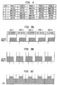
- FIG. 4 shows the phase sequence of the exemplary five-phase motor 380 shown in FIG. 3.
- Phases A and B receive the PWM pulsed signal from the driver 300 shown in FIG. 3.
- Phases B and C are activated and Phases A, D and E are inactivated.
- Phases C and D are activated in a third step
- Phases D and E are activated in a fourth step
- Phases E and A are activated in a fifth step.
- steps 1 to 5 repeat to rotate the rotor of the motor 380 .
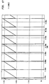
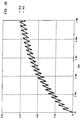
- FIGS. 5A to 5C show steps 1 to 5 of FIG. 4 in graphical form.
- each of the drive pulses for one winding in steps 1 to 5 are shown in FIG. 5A, and the drive pulses for another winding in steps 1 to 5 are shown in FIG. 5B. Note that the drive pulses of the activated windings shown in FIG. 5A are staggered with respect to other substantially simultaneously activated windings shown in FIG. 5B.
- FIG. 5C shows the amount of energy drawn by the motor 380 with respect to the staggered drive pulses shown in FIGS. 5A to 5C. Note that the highest power is drawn at a center of the activation time period, and that the beginning and end portions of the amount of energy drawn during each step is at a minimum, i.e., equal to the power drawn by only a single winding.
- a motor winding having a resistance R and an inductance L is driven with a voltage which is turned on and off at a high frequency.
- the pulse width modulation frequency is in the order of tens of kilohertz above the range of human hearing.
- the current used by the motor winding is varied by varying either the duty cycle or the pulse width of the constant frequency signal.
- the supply voltage V m across a conventional motor winding is opposed by a back EMF voltage having a magnitude E.
- a Fourier analysis In order to predict the current harmonics of a motor, a Fourier analysis must be performed. The Fourier analysis will be performed on the supply current for a right edge aligned PWM pulse and for a left edge aligned PWM pulse. For the case where both phases are energized simultaneously, the supply current will the sum of the current contribution of two right edge aligned PWM pulses. For the case where the two phases are energized by staggered PWM pulses in accordance with the principles of the present invention, the supply current will be the sum of the current contribution of a right edge aligned PWM pulse and a left edge aligned PWM pulse.
- a 0 1 T 0 T f ( t ) dt
- a n 2 T 0 T f ( t )cos 2 ⁇ T tdt
- b n 2 T 0 T f ( t )cos 2 ⁇ T tdt
- nth current harmonic The magnitude of the nth current harmonic is represented by the following equation: C n a n + b n
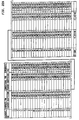
- a staggered pulse width modulation in accordance with the principles of the present invention provides for the calculation of Fourier coefficients of supply current for the left edge aligned PWM pulse and the right edge aligned PWM pulse as follows:
- the harmonic contents of the current waveforms can be determined.
- the current waveform will appear as illustrated in FIG. 7 for one PWM cycle.
- the current waveform in the disclosed embodiment is as shown in FIG. 8.
- the Fourier coefficients for the left and right edge aligned pulses can be used to determine the Fourier coefficients for both the conventional PWM scheme and the staggered PWM method of the present invention.
- the supply current waveforms and harmonics from a test circuit designed to mimic a two phase load which was continuously energized was compared to eliminate as many variables as possible.
- V BEMF DUTY CYCLE (%) * V BEMF MAX
- the back EMF was modeled as a constant DC voltage in opposition with the motor supply voltage. This assumption was made because in a real motor, a phase winding is energized when the back EMF is at a maximum.
- the bottom of the phase was connected back to the positive rail through a freewheeling diode.
- the bottom of the phase coil is connected to the positive rail via a snubber which serves the dual purpose of keeping the back EMF's of non-conducting phases from being conducted to the positive rail and causing braking torque.
- the use of a diode to handle the freewheeling current is a convenient simplification in our case, as the only contribution to the supply current harmonics of interest occur when the phase switches are turned on.
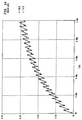
- FIGS. 6-11 illustrate the output simulation results for the supply current and the phase coil currents in each of the phase coils performed over 1 ms.
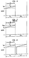
- FIG. 9 illustrates a supply current duty cycle of ten (10%) percent
- FIG. 10 illustrates a phase coil current duty cycle of ten (10%) percent.
- the battery supply current rises to 1.2 A and falls back to zero before the beginning of the next switching period.
- the current falls to zero (0) as the freewheeling diode conducts energy back to the positive supply rail during this time period. Consequently, as a result of the staggered PWM technique in accordance with the principles of the present invention, there is no build up of current in either phase coil and, as a result, minimal torque generated by the motor.
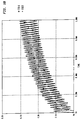
- FIG. 11 illustrates a discontinuous mode wherein a supply current duty cycle is fifty (50%) percent
- FIG. 12 illustrates a phase coil current duty cycle of fifty (50%) percent.
- the supply current when the switches are turned on, the supply current abruptly increases to approximately 8 amps (A), and thereafter increases exponentially until both coils are turned off. The supply current then falls back to zero during the freewheeling portion before the next PWM period. As illustrated in FIG. 12, the current in the coils, however, builds up. At a 50% duty cycle, the motor will deliver a steady RMS torque to the load.
- FIG. 13 illustrates a supply current duty cycle of ninety (90%) percent
- FIG. 14 illustrates a phase coil current duty cycle of ninety (90%) percent.
- the supply current abruptly increases to the value of current present in the coils at the end of the freewheeling portion of the PWM cycle, and then increases exponentially from there until the coil is turned off, where it falls back to zero. In this case, the overall change in the supply current is 12 amps when the switches are turned off.
- the coil current increases during PWM so there will be a steady torque delivered to the motor.
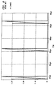
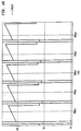
- FIGS. 12 to 17 illustrate results of the disclosed staggered PWM method of the present invention with one energized phase having a left edge aligned PWM waveform and another energized phase having a right edge aligned PWM waveform.
- FIG. 15 illustrates a supply current duty cycle of ten (10%) percent
- FIG. 16 illustrates a phase coil current duty cycle of ten (10%) percent.
- FIG. 16 shows that even at a 10% duty cycle, current will flow in at least one of the coils, albeit for a short period of time. For duty cycles greater than 10 %, there will be a more constant torque generated at lower duty cycles than there would be using the conventional PWM scheme.
- FIG. 17 illustrates a supply current duty cycle of fifty (50%) percent
- FIG. 18 illustrates a phase coil current duty cycle of fifty (50%) percent.
- the supply current never falls to zero, and the value of a supply current ripple is limited to an exponential increase of current in the coils during the time each one is switched on. This value of ripple is approximately equal to 2 A, contrasted with 12.5 A in the conventional PWM technique.
- any noise generated by di/dt using a 50% duty cycle in accordance with the techniques of the present invention will be much less than that generated with the conventional PWM scheme.
- FIG. 18 shows that the current in each coil does not fall to zero, and that the value of current in each coil is equal to the value of current using the conventional prior art PWM scheme.
- FIG. 19 illustrates a supply current duty cycle of ninety (90%) percent
- FIG. 20 illustrates a phase coil current duty cycle of ninety (90%) percent.
- the variation in the supply current is higher than experienced with a duty cycle of 50%. Nevertheless, the current preferably does not fall to zero. Moreover, the variation in the supply current is limited to approximately 1/2 the maximum supply current because, at any given time, one coil is conducting. The value of current in both coils is the same as that experienced in the conventional PWM scheme, as can be seen by comparing the curves in FIG. 19 with those in FIG. 13. Nevertheless, any noise generated by di/dt will be lower than that generated by the conventional PWM scheme.
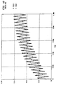
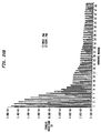
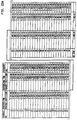
- FIGS. 21A and 21B show that the harmonics generated by the conventional PWM scheme are greater in magnitude than the majority of the harmonics generated by the staggered PWM scheme in accordance with the principles of the present invention.
- the harmonic content of the conventional PWM scheme is also more full than that of the present invention, showing a gradual decrease in magnitude after the nth harmonic. Some of the harmonics generated by the proposed PWM scheme are almost zero. There is a node in the spectrum every 10th harmonic starting at the 5th harmonic. Since the harmonic content of the staggered PWM scheme is smaller than that of the conventional PWM scheme, the noise spectrum of the present staggered PWM scheme will be smaller than that of the conventional PWM scheme.
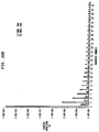
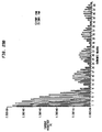
- FIGS. 22A and 22B show dramatic results are achieved at a 50% duty cycle. From FIGS. 22A and 22B show that harmonics generated by the staggered PWM scheme are in a worst case, e.g., about 1/3 of the harmonics generated with the conventional PWM scheme, and that the odd harmonics are almost negligible. This is due to very little ripple on the supply current at a 50% duty cycle. It may be observed that there is a node in the spectrum of the staggered PWM scheme in accordance with the principles of the present invention every second harmonic, starting at the first harmonic.
- the overall spectrum for the noise is lower with the staggered PWM scheme in accordance with the principles of the present invention than it is with the conventional PWM scheme.
- the lower magnitudes of the low frequency harmonics are conventionally the most problematic to suppress, involving the use of large value electrolytic and metalized film capacitors across the supply leads. If the low frequency harmonics are lower, then fewer and smaller filtering elements are required.
- a staggered PWM technique in accordance with the principles of the present invention provides numerous advantages over conventional PWM techniques. For instance, a smaller supply current ripple is obtained, particularly for a unipolar motor, resulting in a lower overall magnitude of supply current harmonics at most frequencies. Moreover, a reduced level of current harmonics is obtained resulting in lower values of noise and electromagnetic interference on the motor supply leads. Where a shared snubber is used as in the case of a unipolar motor, lowered ripple current is obtained through the snubber components, allowing smaller snubbing components.
- the staggered PWM technique in accordance with the principles of the present invention can be extended to n phases by selectively staggering the PWM periods of the phases. Moreover, the staggered PWM technique in accordance with the principles of the present invention can be extended to provide low frequency block commutation to minimize current and torque ripple.
- the technique of the present invention can be implemented to provide block commutation.
- Block commutation involves the energization of a coil without the use of PWM.
- the active phase is kept energized for a fixed period of time as shown in FIG. 26.
- phase activations are staggered in accordance with the principles of the present invention, e.g., as shown in FIGs. 28A to 28C.
- FIG. 28A shows the activation of a first phase with respect to the activation of a second phase in FIG. 28B.
- the resulting current drawn from the power supply is depicted in FIG. 28C.
- staggered activation of the block commutation phases in accordance with the principles of the present invention is easier on the power supply and results in lower torque pulsations.
- audible noise is lowered and thus is easier on the load as well.
- linear control of the transistors could be used to avoid pulsations in the torque and/or current when the phase back EMFs are lower.
Landscapes
- Engineering & Computer Science (AREA)
- Power Engineering (AREA)
- Control Of Ac Motors In General (AREA)
- Control Of Motors That Do Not Use Commutators (AREA)
Applications Claiming Priority (4)
| Application Number | Priority Date | Filing Date | Title |
|---|---|---|---|
| US6303297P | 1997-10-23 | 1997-10-23 | |
| US63032P | 1997-10-23 | ||
| US100000 | 1998-06-19 | ||
| US09/100,000 US6331757B1 (en) | 1998-06-19 | 1998-06-19 | Staggered pulse width modulation apparatus and method for EMI minimization in motor |
Publications (2)
| Publication Number | Publication Date |
|---|---|
| EP0911956A2 true EP0911956A2 (fr) | 1999-04-28 |
| EP0911956A3 EP0911956A3 (fr) | 1999-11-17 |
Family
ID=26742987
Family Applications (1)
| Application Number | Title | Priority Date | Filing Date |
|---|---|---|---|
| EP98119805A Withdrawn EP0911956A3 (fr) | 1997-10-23 | 1998-10-15 | Appareil de modulation à largeur d'impulsion échelonnée et méthode de minimisation des interférences électromagnétiques dans les moteurs |
Country Status (1)
| Country | Link |
|---|---|
| EP (1) | EP0911956A3 (fr) |
Cited By (3)
| Publication number | Priority date | Publication date | Assignee | Title |
|---|---|---|---|---|
| WO2000070738A3 (fr) * | 1999-05-19 | 2002-05-02 | Bosch Gmbh Robert | Procede pour commander au moins un consommateur inductif au moyen de signaux de commande a modulation d'impulsions en duree |
| FR2853782A1 (fr) * | 2003-04-11 | 2004-10-15 | Bosch Gmbh Robert | Dispositif de commande a compatibilite electromagnetique optimise pour une machine soufflante |
| GB2456351A (en) * | 2008-01-14 | 2009-07-15 | Pml Flightlink Ltd | Hub motor with individually controlled stator coils provides safe braking |
Family Cites Families (5)
| Publication number | Priority date | Publication date | Assignee | Title |
|---|---|---|---|---|
| DE2745824B1 (de) * | 1977-10-12 | 1979-03-29 | Demag Ag | Umrichter mit Gleichstrom-Zwischenkreis zur Speisung eines Drehstrommotors |
| JPH06189593A (ja) * | 1992-12-16 | 1994-07-08 | Canon Inc | モータ制御方法及び制御装置 |
| US5627443A (en) * | 1994-04-06 | 1997-05-06 | Unisia Jecs Corporation | Method of driving stepping motor |
| JPH08154395A (ja) * | 1994-11-29 | 1996-06-11 | Aisan Ind Co Ltd | ブラシレスdcモータ |
| JPH08242587A (ja) * | 1995-03-01 | 1996-09-17 | Toshiba Corp | Pwmインバータの制御方法 |
-
1998
- 1998-10-15 EP EP98119805A patent/EP0911956A3/fr not_active Withdrawn
Cited By (5)
| Publication number | Priority date | Publication date | Assignee | Title |
|---|---|---|---|---|
| WO2000070738A3 (fr) * | 1999-05-19 | 2002-05-02 | Bosch Gmbh Robert | Procede pour commander au moins un consommateur inductif au moyen de signaux de commande a modulation d'impulsions en duree |
| US6667667B1 (en) | 1999-05-19 | 2003-12-23 | Robert Bosch Gmbh | Method for driving at least one inductive load using pulse width modulated control signals |
| FR2853782A1 (fr) * | 2003-04-11 | 2004-10-15 | Bosch Gmbh Robert | Dispositif de commande a compatibilite electromagnetique optimise pour une machine soufflante |
| GB2456351A (en) * | 2008-01-14 | 2009-07-15 | Pml Flightlink Ltd | Hub motor with individually controlled stator coils provides safe braking |
| GB2456351B (en) * | 2008-01-14 | 2013-02-27 | Protean Electric Ltd | Vehicle with in-wheel motor brake |
Also Published As
| Publication number | Publication date |
|---|---|
| EP0911956A3 (fr) | 1999-11-17 |
Similar Documents
| Publication | Publication Date | Title |
|---|---|---|
| US7088595B2 (en) | Reversible buck-boost chopper circuit, and inverter circuit with the same | |
| Kim et al. | A PWM buck-boost AC chopper solving the commutation problem | |
| JPH11196599A (ja) | ジェネレータの調整装置および方法 | |
| KR20110105406A (ko) | 영구 자석 교류기용 제어기 | |
| JPH04229021A (ja) | 電力発生装置 | |
| EP0783203B1 (fr) | Convertisseur de puissance en pont | |
| US6137256A (en) | Soft turn-off controller for switched reluctance machines | |
| US6759826B2 (en) | Control strategy for switched reluctance drive systems | |
| US6331757B1 (en) | Staggered pulse width modulation apparatus and method for EMI minimization in motor | |
| EP1503492B1 (fr) | Contrôl de courant d'une inductance à modulation de largeur d'impulsion à fréquence contrôlée | |
| JP2019501620A (ja) | 三相モータへの電力供給を切り換えるためのソフトウェア制御された電子回路 | |
| CN107769672A (zh) | 用于运行电机的方法以及电机 | |
| KR102660212B1 (ko) | 펄스형 전기 기계 제어를 위한 승압 변환기 | |
| EP0911956A2 (fr) | Appareil de modulation à largeur d'impulsion échelonnée et méthode de minimisation des interférences électromagnétiques dans les moteurs | |
| JP2000505640A (ja) | 電子整流型の高能率電気モータ | |
| JP2001186770A (ja) | 電源装置およびこれを用いた電動機または圧縮機駆動システム | |
| JP2004201453A (ja) | 直流3相ブラシレスモータの駆動装置 | |
| EP0822650B1 (fr) | Appareil de commande pour un moteur sans balai | |
| CN107769671B (zh) | 用于运行电机的方法以及电机 | |
| EP0627809A2 (fr) | Méthode de commande d'un onduleur pour alimenter un moteur asynchrone | |
| CN103168415B (zh) | 用于脉宽调制式控制脉冲控制逆变器的开关元件的方法和控制单元 | |
| JP3258743B2 (ja) | ブラシレスモータ駆動装置 | |
| JP2007252135A (ja) | ブラシレスモータの駆動装置 | |
| JP2001231270A (ja) | インバータ装置 | |
| JP4052063B2 (ja) | Srモータの制御装置 |
Legal Events
| Date | Code | Title | Description |
|---|---|---|---|
| PUAI | Public reference made under article 153(3) epc to a published international application that has entered the european phase |
Free format text: ORIGINAL CODE: 0009012 |
|
| AK | Designated contracting states |
Kind code of ref document: A2 Designated state(s): DE FR GB IT |
|
| AX | Request for extension of the european patent |
Free format text: AL;LT;LV;MK;RO;SI |
|
| PUAL | Search report despatched |
Free format text: ORIGINAL CODE: 0009013 |
|
| 17P | Request for examination filed |
Effective date: 19990922 |
|
| AK | Designated contracting states |
Kind code of ref document: A3 Designated state(s): AT BE CH CY DE DK ES FI FR GB GR IE IT LI LU MC NL PT SE |
|
| AX | Request for extension of the european patent |
Free format text: AL;LT;LV;MK;RO;SI |
|
| AKX | Designation fees paid |
Free format text: DE FR GB IT |
|
| RAP1 | Party data changed (applicant data changed or rights of an application transferred) |
Owner name: SIEMENS VDO AUTOMOTIVE INC. |
|
| 17Q | First examination report despatched |
Effective date: 20040301 |
|
| GRAP | Despatch of communication of intention to grant a patent |
Free format text: ORIGINAL CODE: EPIDOSNIGR1 |
|
| GRAS | Grant fee paid |
Free format text: ORIGINAL CODE: EPIDOSNIGR3 |
|
| STAA | Information on the status of an ep patent application or granted ep patent |
Free format text: STATUS: THE APPLICATION IS DEEMED TO BE WITHDRAWN |
|
| 18D | Application deemed to be withdrawn |
Effective date: 20070503 |