EP0912067A2 - Mise à l'échelle des signaux de sortie d'une cathode - Google Patents
Mise à l'échelle des signaux de sortie d'une cathode Download PDFInfo
- Publication number
- EP0912067A2 EP0912067A2 EP98308752A EP98308752A EP0912067A2 EP 0912067 A2 EP0912067 A2 EP 0912067A2 EP 98308752 A EP98308752 A EP 98308752A EP 98308752 A EP98308752 A EP 98308752A EP 0912067 A2 EP0912067 A2 EP 0912067A2
- Authority
- EP
- European Patent Office
- Prior art keywords
- signal
- electron gun
- offset
- processor
- scaled
- Prior art date
- Legal status (The legal status is an assumption and is not a legal conclusion. Google has not performed a legal analysis and makes no representation as to the accuracy of the status listed.)
- Withdrawn
Links
Images



Classifications
-
- H—ELECTRICITY
- H04—ELECTRIC COMMUNICATION TECHNIQUE
- H04N—PICTORIAL COMMUNICATION, e.g. TELEVISION
- H04N17/00—Diagnosis, testing or measuring for television systems or their details
- H04N17/04—Diagnosis, testing or measuring for television systems or their details for receivers
Definitions
- the present invention relates in general to monitors, and more particularly, to a method and apparatus for providing cathode output scaling so as to provide optimization of the cathode output.
- Cathode ray tubes are typically employed in electronic display systems, such as a television receiver or a display apparatus including a CRT numerical display.
- Each color CRT consists of three electron guns (a red, a white and a blue electron gun) and a phosphor screen that is located inside an evacuated glass envelope.
- Each electron gun generates a beam of electrons that is accelerated towards the screen by a positive anode voltage.
- Luminance indicates the amount of light intensity which is perceived by the eye as brightness, while the control of luminance is termed "white balance" since white light may be considered and provided as a mixture of the red, green and blue primary colors in the proper proportions.
- the CRTs are typically subjected to a process known as "aging" during manufacture.
- This process involves the warming up of cathode ray tubes ("CRT") to facilitate testing of circuitry and adjustment of various display parameters such as color convergence and picture geometry.
- Conventional aging techniques typically involve applying a single input voltage to each of the three electron guns to cause each electron gun to generate the corresponding luminance.
- each electron gun since each electron gun generates a different color, each of the electron guns also operates to provide an optimum output at a different frequency and at a different input voltage. This input voltage varies from one electron gun to another.
- the inputs and/or outputs of the electron guns are not adjusted to ensure that the output of each electron gun is optimized.
- the present invention relates a method and system for scaling the output of an electron gun in a cathode ray tube.
- the system comprises an electron gun located in the cathode ray tube and a memory configured to store an offset value representative of a difference between a maximum output level and an unadjusted output level of the electron gun.
- the system further comprises a processor coupled to the memory.
- the processor generates a first signal representative of an input voltage corresponding to the unadjusted output level of the electron gun, and the processor generates an offset signal representative of the offset.
- a summing circuit is coupled between the processor and the electron gun, which combines the first and the offset signals to provide a scaled signal.
- the electron gun receives the scaled signal and generates an optimized output based on the scaled signal.
- the scaling technique may also be applied to a second and a third electron guns.
- Figure 1 is a cross sectional view of a conventional cathode ray tube.
- FIG. 2 is a block diagram of one embodiment of a calibration system provided in accordance with the principles of the present invention.
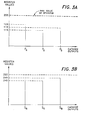
- Figure 3A illustrates examples of the detected outputs of the electron guns 132a, 132b and 132c.
- Figure 3B illustrates the adjusted or scaled values of the detect outputs of the electron guns 132a, 132b and 132c.
- Figure 4 illustrates a display system 200 that implements the cathode output scaling process of the present invention.
- the present invention is an apparatus and method for scaling the output(s) of one or more electron guns in a cathode ray tube, so as to provide optimization of the electron gun output(s).
- the CRT 10 consists of an electron gun 12 and a phosphor screen 14 that is located inside an evacuated glass envelope 16.
- the narrow neck 18 of the CRT 10 contains the electron gun 12, which generates a beam of electrons 15.
- the beam is accelerated towards the screen 14 by a positive anode voltage.
- the anode 20 is a conductive coating on the inside surface of the wide glass bell portion of the CRT 10.
- the inside of the faceplate 22 is coated with a luminescent material that produces light when excited by electrons in the beam 15.
- a monochrome picture tube has one electron gun and a continuous phosphor coating that produces a picture in black and white.
- the screen 14 is formed with dot trios or vertical lines of red, green and blue phosphors. In such color picture tubes, there are three electron beams, one for each color phosphor. Each of the three electron beams is emitted by a separate cathode.
- the present invention first determines the input voltage corresponding to the maximum output for each cathode.
- the appropriate values are stored in memory in the display system for use during operation of the CRT.
- Figure 2 illustrates a calibration system 100 that performs the cathode output determination process in accordance with the principles of the present invention.
- the calibration system 100 comprises a processing system 110, a video preamplifier circuit or video processing circuit 120 that includes a register block 122, a CRT 130 (such as the CRT10) that includes a red electron gun 132a, a green electron gun 132b and a blue electron gun 132c, an adjustment and inspection circuit 140 that includes a sensor 142, and a memory module 150 such as an erasable electrically programmable read only memory (EEPROM).
- EEPROM erasable electrically programmable read only memory
- the processing system 110 is a controller. In another embodiment, the processing system 110 comprises a processor 112 and memory 114 such as a random access memory (RAM). Examples of the processor 112 include the PentiumTM and the Pentium ProTM processors.
- the processing system 110 is coupled to the video preamplifier circuit 120 via signal line 116. In one embodiment, the signal line 116 is an inter-integrated circuit (I 2 C) bus.
- the register block 122 is coupled to each of the electron gun 132a, 132b and 132c via a corresponding signal line 142a, 142b and 142c.
- the video preamplifier circuit 120 is the RGB Video Preamplifier as marketed by Sony-Corp. under the part designation CXA2055P.
- the processing system 110 issues control and data signals to the video preamplifier circuit 120 to control the output of each electron gun 132a, 132b and 132c.
- the processor 112 generates digital control signals that are provided to the video preamplifier circuit 120.
- the digital control signals are stored in the register block 122 subsequently provided as analog luminance signals to the respective electron guns 132a, 132b and 132c.
- the control signals include values for operating each electron gun 132a, 132b and/or 132c at predetermined luminance levels, as described in detail in the following sections.
- the sensor 142 detects the color temperature corresponding to the output generated by each electron gun 132a, 132b and 132c.
- the color temperature of the output of each electron gun 132a, 132b and 132c corresponds to the magnitude of the output of each electron gun 132a, 132b and 132c.
- the detected temperatures are provided to the adjustment and inspection circuit 140, which subsequently provides values corresponding to the detected temperatures to the processing system 110.
- the processing system 110 stores the values of the detected temperatures in the memory module 150. In this manner, the electron gun 132a, 132b or 132c with the most dominant output or the highest output value may be identified.
- the outputs of the remaining electron guns may be obtained so that scaling, as described in the following sections, may be provided.
- the adjustment and inspection circuit 140 is the Adjustment and Inspection display as marketed by Sony Corp. under the part designation CPD-100GS.
- the process for detecting the outputs of the electron guns 132a, 132b and 132c may be performed using the Adjustment/Inspection Standard TS-6999-919M-10.
- FIG. 3A illustrates examples of the detected outputs of the electron guns 132a, 132b and 132c.
- the output of the red electron gun 132a provides an output PR that is the maximum output, and is recorded in an 8 bit register with a value of 125.
- the output of the green electron gun 132b provides an output P G with a value of 115, while that of the blue electron gun 132c provides an output P B with a value of 119.
- the adjusted outputs S R , S G and S B of the respective electron guns 132a, 132b and 132c will be as follows:
- Figure 3B illustrates the adjusted or scaled values of the detect outputs of the electron guns 132a, 132b and 132c.
- the adjusted or scaled output values of the electron guns 132a, 132b and 132c are stored in memory 150. Once stored, the adjustment and inspection circuit 140, along with the sensor 142 may be disconnected from the processing system 110.
- FIG. 4 illustrates a display system 200 that implements the cathode output scaling process of the present invention.
- the display system 200 comprises the processing system 110, the video preamplifier circuit 120, the CRT 130, the memory module 150, a direct current (DC) control circuit 160 and a summing circuit 170.
- the processor 112 first retrieves the offset D from the memory 150. It then issues control and data signals to the video preamplifier circuit 120 via signal line 116.
- the processor 112 issues a first control signal to fire the electron guns 132a, 132b, 132c at their normal output values.
- a second control signal is provided to the video preamplifier circuit 120 to provide the offset D to a DC control cutoff circuit 160.
- the values corresponding to the control and data signals are stored in register block 122.
- the value of the first control signal is stored in a first register location 122a
- the value of the second control signal and the value of D are stored in a second register location 122b.
- the value of the first register location 122a is provided as an analog control signal to each summer 172a, 172b and 172c
- the values stored in the second register location 122b are provided to each DAC 124a, 124b and 124c, which converts the digital value D stored in the second register location 122b to an analog offset signal, that is subsequently provided to the DC control cutoff circuit 160.
- the DC control cutoff circuit 160 amplifies the output of the DACs 124a, 124b and 124c to provide a DC cutoff value to each summer 172a, 172b and 172c in the summing circuit 170.
- Each summer 172a, 172b and 172c adds the offset to the normal output values of the electron guns 132a, 132b and 132c and provides the resulting signal as a control signal for controlling the output of the electron guns 132a, 132b and 132c.
- the output of the red electron gun 132a will be provided at a maximum value, while the outputs of the remaining two electron guns 132b and 132c will be scaled accordingly.
- the present invention thus provides a method and apparatus for providing suitable input voltages to each cathode in a cathode ray tube so as to provide optimization of the cathode output for each electron gun in a cathode ray tube.
Landscapes
- Engineering & Computer Science (AREA)
- Health & Medical Sciences (AREA)
- Biomedical Technology (AREA)
- General Health & Medical Sciences (AREA)
- Multimedia (AREA)
- Signal Processing (AREA)
- Manufacture Of Electron Tubes, Discharge Lamp Vessels, Lead-In Wires, And The Like (AREA)
- Processing Of Color Television Signals (AREA)
- Amplifiers (AREA)
Applications Claiming Priority (2)
| Application Number | Priority Date | Filing Date | Title |
|---|---|---|---|
| US08/958,096 US5977711A (en) | 1997-10-27 | 1997-10-27 | Method and system for optimizing cathode output for aging a cathode ray tube during manufacture |
| US958096 | 1997-10-27 |
Publications (2)
| Publication Number | Publication Date |
|---|---|
| EP0912067A2 true EP0912067A2 (fr) | 1999-04-28 |
| EP0912067A3 EP0912067A3 (fr) | 2000-11-15 |
Family
ID=25500589
Family Applications (1)
| Application Number | Title | Priority Date | Filing Date |
|---|---|---|---|
| EP98308752A Withdrawn EP0912067A3 (fr) | 1997-10-27 | 1998-10-27 | Mise à l'échelle des signaux de sortie d'une cathode |
Country Status (4)
| Country | Link |
|---|---|
| US (1) | US5977711A (fr) |
| EP (1) | EP0912067A3 (fr) |
| JP (1) | JPH11329249A (fr) |
| KR (1) | KR19990037409A (fr) |
Cited By (1)
| Publication number | Priority date | Publication date | Assignee | Title |
|---|---|---|---|---|
| CN104576265A (zh) * | 2014-12-31 | 2015-04-29 | 中国科学院西安光学精密机械研究所 | 条纹变像管偏转方向及阴极面的标定系统及标定方法 |
Families Citing this family (1)
| Publication number | Priority date | Publication date | Assignee | Title |
|---|---|---|---|---|
| DE19856384A1 (de) * | 1998-12-07 | 2000-06-08 | Siemens Ag | Verfahren und Schaltungsanordnung zur Regelung des Arbeitspunktes einer Kathodenstrahlröhre |
Family Cites Families (13)
| Publication number | Priority date | Publication date | Assignee | Title |
|---|---|---|---|---|
| US4386345A (en) * | 1981-09-22 | 1983-05-31 | Sperry Corporation | Color and brightness tracking in a cathode ray tube display system |
| US4563649A (en) * | 1983-07-11 | 1986-01-07 | Sencore, Inc. | Cathode ray tube tracking tester and method of testing |
| US4706108A (en) * | 1985-04-12 | 1987-11-10 | Sony Corporation | Automatic setup system for controlling color gain, hue and white balance of TV monitor |
| US4875032A (en) * | 1987-10-26 | 1989-10-17 | Mcmanus Paul A | Method and apparatus for processing colorimetric parameters of a color sample |
| JP3003134B2 (ja) * | 1989-07-14 | 2000-01-24 | ソニー株式会社 | テレビジョン受像機 |
| JP3097105B2 (ja) * | 1990-07-13 | 2000-10-10 | ソニー株式会社 | モニタ装置 |
| US5371537A (en) * | 1991-10-31 | 1994-12-06 | Eastman Kodak Company | Method and apparatus for automatically calibrating a CRT display |
| JPH05236498A (ja) * | 1992-02-20 | 1993-09-10 | Matsushita Electric Ind Co Ltd | ホワイトバランス自動調整装置 |
| US5821917A (en) * | 1993-03-24 | 1998-10-13 | Apple Computer, Inc. | System and method to compensate for the effects of aging of the phosphors and faceplate upon color accuracy in a cathode ray tube |
| US5512961A (en) * | 1993-03-24 | 1996-04-30 | Apple Computer, Inc. | Method and system of achieving accurate white point setting of a CRT display |
| KR0138285B1 (ko) * | 1995-01-20 | 1998-05-15 | 김광호 | 버스 제어방식을 채용한 텔레비젼과 그 제어방법 |
| KR0141168B1 (ko) * | 1995-01-20 | 1998-06-15 | 김광호 | 버스제어방식을 채용한 텔레비젼의 자동화생산장치 및 그 방법 |
| JPH099304A (ja) * | 1995-06-24 | 1997-01-10 | Matsushita Electric Ind Co Ltd | ビーム位置シミュレーション調整装置 |
-
1997
- 1997-10-27 US US08/958,096 patent/US5977711A/en not_active Expired - Fee Related
-
1998
- 1998-10-27 EP EP98308752A patent/EP0912067A3/fr not_active Withdrawn
- 1998-10-27 JP JP10305183A patent/JPH11329249A/ja not_active Withdrawn
- 1998-10-27 KR KR1019980044985A patent/KR19990037409A/ko not_active Withdrawn
Cited By (1)
| Publication number | Priority date | Publication date | Assignee | Title |
|---|---|---|---|---|
| CN104576265A (zh) * | 2014-12-31 | 2015-04-29 | 中国科学院西安光学精密机械研究所 | 条纹变像管偏转方向及阴极面的标定系统及标定方法 |
Also Published As
| Publication number | Publication date |
|---|---|
| KR19990037409A (ko) | 1999-05-25 |
| EP0912067A3 (fr) | 2000-11-15 |
| JPH11329249A (ja) | 1999-11-30 |
| US5977711A (en) | 1999-11-02 |
Similar Documents
| Publication | Publication Date | Title |
|---|---|---|
| US5512961A (en) | Method and system of achieving accurate white point setting of a CRT display | |
| US5821917A (en) | System and method to compensate for the effects of aging of the phosphors and faceplate upon color accuracy in a cathode ray tube | |
| US7403175B1 (en) | Methods and systems for compensating row-to-row brightness variations of a field emission display | |
| WO1997004601A9 (fr) | Systeme et procede de compensation des consequences du vieillissement des luminophores et de la dalle sur la precision des couleurs dans un tube cathodique | |
| US20070063927A1 (en) | Method of driving plasma display panel and apparatus thereof | |
| JP2000260331A (ja) | プラズマディスプレイ装置 | |
| US5977711A (en) | Method and system for optimizing cathode output for aging a cathode ray tube during manufacture | |
| KR20030097507A (ko) | 평판 표시 장치의 색도 보정 장치 및 그 방법 | |
| JP3478757B2 (ja) | 画像表示制御方法及び装置 | |
| US6441563B1 (en) | Dynamic color temperature and color deviation calibration method | |
| US5939843A (en) | Adaptive convergence adjustment for multi-scan monitor | |
| US6034742A (en) | Adaptive sharpness enhancement for a multi-frequency scanning monitor | |
| US5892544A (en) | Beam current detection and control system for a cathode ray tube | |
| US6348944B1 (en) | Selective aging for monitor production | |
| JPH1169370A (ja) | カラー画像表示装置 | |
| EP1258858A1 (fr) | Procédé dynamique de calibrage de couleurs | |
| US6605898B2 (en) | CRT device with improved resolution | |
| KR100513020B1 (ko) | 플라즈마 디스플레이 패널의 콘트라스트 제어장치 및 방법 | |
| EP1363312A2 (fr) | Unite d'affichage a image couleur | |
| EP1258857A1 (fr) | Procédé de compensation des effets du vieillissement dans un écran à plasma | |
| KR0159583B1 (ko) | 컨버전스 측정장치 및 방법 | |
| JP2000358253A (ja) | 自動白バランス調整回路を備えたカラー受像管を用いたディスプレイ | |
| JP2964904B2 (ja) | ホワイトバランス制御回路および制御方法 | |
| KR100546621B1 (ko) | 기준 백색 보정 장치를 구비한 평판 디스플레이 장치 및그의 기준 백색 보정 방법 | |
| JP2001008226A (ja) | 自動白バランス調整回路を有するカラー受像管を用いたディスプレイ |
Legal Events
| Date | Code | Title | Description |
|---|---|---|---|
| PUAI | Public reference made under article 153(3) epc to a published international application that has entered the european phase |
Free format text: ORIGINAL CODE: 0009012 |
|
| AK | Designated contracting states |
Kind code of ref document: A2 Designated state(s): AT BE CH CY DE DK ES FI FR GB GR IE IT LI LU MC NL PT SE |
|
| AX | Request for extension of the european patent |
Free format text: AL;LT;LV;MK;RO;SI |
|
| PUAL | Search report despatched |
Free format text: ORIGINAL CODE: 0009013 |
|
| AK | Designated contracting states |
Kind code of ref document: A3 Designated state(s): AT BE CH CY DE DK ES FI FR GB GR IE IT LI LU MC NL PT SE |
|
| AX | Request for extension of the european patent |
Free format text: AL;LT;LV;MK;RO;SI |
|
| RIC1 | Information provided on ipc code assigned before grant |
Free format text: 7H 04N 17/04 A, 7H 01J 9/42 B, 7H 01J 9/44 B |
|
| AKX | Designation fees paid | ||
| REG | Reference to a national code |
Ref country code: DE Ref legal event code: 8566 |
|
| STAA | Information on the status of an ep patent application or granted ep patent |
Free format text: STATUS: THE APPLICATION IS DEEMED TO BE WITHDRAWN |
|
| 18D | Application deemed to be withdrawn |
Effective date: 20010516 |