EP0912372B1 - Assemblage de cablage electrique sur un panneau de garnissage - Google Patents
Assemblage de cablage electrique sur un panneau de garnissage Download PDFInfo
- Publication number
- EP0912372B1 EP0912372B1 EP97933439A EP97933439A EP0912372B1 EP 0912372 B1 EP0912372 B1 EP 0912372B1 EP 97933439 A EP97933439 A EP 97933439A EP 97933439 A EP97933439 A EP 97933439A EP 0912372 B1 EP0912372 B1 EP 0912372B1
- Authority
- EP
- European Patent Office
- Prior art keywords
- trim panel
- retainers
- wire
- routing elements
- electrical
- Prior art date
- Legal status (The legal status is an assumption and is not a legal conclusion. Google has not performed a legal analysis and makes no representation as to the accuracy of the status listed.)
- Expired - Lifetime
Links
- 238000000034 method Methods 0.000 claims description 16
- 239000003292 glue Substances 0.000 description 4
- 238000009434 installation Methods 0.000 description 3
- 238000009417 prefabrication Methods 0.000 description 3
- 238000005299 abrasion Methods 0.000 description 2
- 239000000853 adhesive Substances 0.000 description 2
- 230000001070 adhesive effect Effects 0.000 description 2
- 230000000712 assembly Effects 0.000 description 2
- 238000000429 assembly Methods 0.000 description 2
- 238000010276 construction Methods 0.000 description 2
- 230000005611 electricity Effects 0.000 description 2
- 239000002390 adhesive tape Substances 0.000 description 1
- 230000001419 dependent effect Effects 0.000 description 1
- 239000012943 hotmelt Substances 0.000 description 1
- 230000014759 maintenance of location Effects 0.000 description 1
- 239000002184 metal Substances 0.000 description 1
- 238000012986 modification Methods 0.000 description 1
- 230000004048 modification Effects 0.000 description 1
- 238000000465 moulding Methods 0.000 description 1
- 238000009941 weaving Methods 0.000 description 1
Images


Classifications
-
- B—PERFORMING OPERATIONS; TRANSPORTING
- B60—VEHICLES IN GENERAL
- B60R—VEHICLES, VEHICLE FITTINGS, OR VEHICLE PARTS, NOT OTHERWISE PROVIDED FOR
- B60R16/00—Electric or fluid circuits specially adapted for vehicles and not otherwise provided for; Arrangement of elements of electric or fluid circuits specially adapted for vehicles and not otherwise provided for
- B60R16/02—Electric or fluid circuits specially adapted for vehicles and not otherwise provided for; Arrangement of elements of electric or fluid circuits specially adapted for vehicles and not otherwise provided for electric constitutive elements
- B60R16/0207—Wire harnesses
- B60R16/0215—Protecting, fastening and routing means therefor
-
- B—PERFORMING OPERATIONS; TRANSPORTING
- B60—VEHICLES IN GENERAL
- B60R—VEHICLES, VEHICLE FITTINGS, OR VEHICLE PARTS, NOT OTHERWISE PROVIDED FOR
- B60R16/00—Electric or fluid circuits specially adapted for vehicles and not otherwise provided for; Arrangement of elements of electric or fluid circuits specially adapted for vehicles and not otherwise provided for
- B60R16/02—Electric or fluid circuits specially adapted for vehicles and not otherwise provided for; Arrangement of elements of electric or fluid circuits specially adapted for vehicles and not otherwise provided for electric constitutive elements
- B60R16/0207—Wire harnesses
Definitions
- the subject invention relates to a method and trim panel construction for routing and retaining electrical wires in a vehicle trim panel.
- One example of the invention may be used in a vehicle door panel.
- An automobile door frequently houses numerous electrical components and devices for carrying out various tasks and operations.
- the door may include an electric motor for controlling up and down movements of a window, an electric solenoid for controlling a door lock, an electric motor for controlling a side view mirror, an electronic switching module (i.e., a mux box), loud speakers, lights, and controlling features such as power window switches, a power lock switch, power seat control switches, and the like.
- a plurality of electrical wires are routed within the door for connecting the various electrical components to each other, to other complimentary features, and to a source of electricity.
- the electrical wires are pre-assembled into a wiring harness. Because the prior art wiring harnesses are pre-assembled and shipped to the assembly line for installation at the time of assembly of the automobile, it is necessary to create inventory for the wiring harnesses. In addition, the connection of wire harness to both the trim panel and the vehicle is complicated and difficult.
- the present invention provides a method as defined in Claim 1 hereinafter.
- the method many include the features of dependent Claim 2.
- the subject invention overcomes the disadvantages of the prior art by eliminating the wiring harness prefabrication process entirely. Instead, the individual electrical wires are routed directly on the outer surface of the trim panel, such that there is no inventory, cataloging or shipment concerns apart for the trim panel itself. Also, the subject method eliminates one step on the assembly line, namely the separate attachment of a wiring harness to the frame or to the trim panel.
- the wire routing elements are a pair of opposed retainers which are molted integrally with the trim panel, and which are formed about a well.
- the retainers are connected to one edge of the well and extend toward an opposed side of the well.
- the retainer is spaced from the opposed side, such that the retainer effectively provides a locking finger.
- the two retainers extend in opposed directions such that one of the retainers is attached to each of the two edges.
- the wire is initially snapped beneath one of the retainers and then is snapped beneath the other. In this way, the wire is held securely against any shaking or rocking that the trim panel may experience.
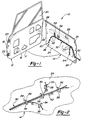
- an automobile door assembly is generally shown at 10 in Figure 1.
- the door assembly 10 includes a structural door frame, generally indicated at 12, and a trim panel, generally indicated at 14.
- the door frame 12 typically includes a hollow body 16 welded together from multiple pieces of stamped sheet metal. The inner surface of the body 16 is referenced at 17.
- Devices are provided inside the hollow body 16, such as an electric motor 18 for controlling up and down movements of a window 20, an electric solenoid 22 for controlling a door lock (not shown). This listing is not meant to be exhaustive.
- Hinges 23 are shown on the one edge of the door frame 12 for pivotally attaching the door frame 12 to the A-pillar (or B-pillar or other portion of the automobile body) of the automobile.
- the trim panel 14 includes an outer surface 24 which is adapted to overlie the body 16 of the door frame 12, and an interior surface 26 presented toward and visible to the passenger compartment of the automobile.
- the interior surface 26 of the trim panel 14 will usually include electrical components in the form of controlling features such as power window switches, a power lock switch, power seat control switches, and the like.
- the trim panel 14 may also include loud speakers and lighting features (not shown).
- the trim panel 14 is attached to the body 16 of the door frame 12 such as by self-locking push retainers 28.
- a plurality of electrical wires are secured to the outer surface 24 of the trim panel 14 for electrically connecting the various electrical devices to each other and to a source of electricity.
- the electrical wires 30 of the subject invention are independently and sequentially routed between their respective origination and destination points directly on the outer surface 24 of the trim panel 14. In this manner, the entire prefabrication step can be avoided, thereby conserving time investments, as well as reducing the inventory, cataloging and shipping concerns raised by the prior art wiring harness assemblies.
- wire routing elements are formed on the outer surface 24 of the trim panel 14 for individually and sequentially securing the electrical wires 30 therealong.
- One possible construction of the routing elements comprises L-shaped posts 32 integrally formed with the trim panel 14 at the time of its molding. These L-shaped posts 32 may point in alternating directions so that the electrical wires 30 are woven or laced back and forth between the posts 32, and thereby secured in position to protect the wires from abrasion damage and from causing rattling noises.
- the arrangement and spacing of the posts 32 in Figure 1 is provided for illustrative purposes only.
- the routing elements comprise tabs 34, each having a V-shaped receiving notch 36.
- the base (vertex) of each receiving notch 36 is formed a pocket 38 in which the wire or wires are seated.
- the electrical wires 30 are routed one-at-a-time between adjacent tabs 34, with each wire being forcibly inserted into the receiving notch 36 until seated in the pocket 38 to securely retain it in its routed position.
- the outer surface 24 of the trim panel 14 may include printed or molded (either embossed or inset) instructional indicia 40 to assist the worker in routing the various wires between their respective origination and destination points.
- the instructional indicia may include a dashed line and a wire color identifier.
- the instructional indicia may be used with any of the other embodiments of the subject invention described herein.
- the routing elements comprise a series of channels 42 extending between the respective origination and destination points of the several wires.
- a glue 44 (or other form of adhesive, such as tape or the like) may be placed in strategic locations along the channels.
- a typical industrial hot-melt glue 44 will provide satisfactory results.
- the glue 44 may be used with any of the other embodiments of the subject invention described herein to further enhance retention of the wires 30 in their routed positions to prevent abrasion and vibration.
- the routing elements include a plurality of self-locking strap-like clamps 46.
- the clamps 46 may either be integrally formed with the trim panel 14 or be loose piece fabricated and then assembled to the trim panel 14 in a subassembly process.
- the clamps 46 include a barbed push fastener 48 which seats in hole 50 in the outer surface 24 of the trim panel 14.
- the wires 30 are shown including electrical connectors at their respective terminal ends.
- the connectors allow convenient assembly and, perhaps as importantly, convenient serviceability of the related components.
- a primary connector 52 attaches all of the origination ends of the wires for receiving electrical power from a source and transmitting signals to various electrical devices.
- This primary connector 52 mates with a complimentary connector (not shown) adjacent the A-pillar (or other portion of the automobile body).
- a window motor connector 54 couples to the window motor 18.
- a window switch connector 56 couples to the power window control switch (not shown).
- a lock switch connector 58 couples to the power lock control switch (not shown).
- a solenoid connector 60 couples to the lock solenoid 22.
- additional components, both controlling and controlled devices may be networked with wires 30 routed in the trim panel 14.
- the method for carrying out the subject invention comprises the steps of forming a structural vehicle frame, such as a door frame 12, having an inner surface 17, forming a trim panel 14 having an outer surface 24 adapted to overlie the inner surface 17 of the door frame 12, and positioning a plurality of electrical devices in the door frame 12 and the trim panel 14.
- the improvement comprises forming wire routing elements on the outer surface 24 of the trim panel 14 and then individually and sequentially securing a plurality of electrical wires 30 along the routing elements to the electrical devices to eliminate the need for a prefabricated wiring harness.
- Instructional routing indicia 40 may be displayed on the outer surface 24 of the trim panel 14 to facilitate the routing process. In a sense, the wire harness is formed on the trim panel.
- the outer surface 24 of the trim panel 14 is attached to the inner surface 17 of the door frame 12.
- the step of securing the electrical wires 30 includes applying an adhesive, which may be in the form of glue 44 or an adhesive tape.
- an adhesive which may be in the form of glue 44 or an adhesive tape.
- Alternative methods of securing the electrical wires 30 including weaving or lacing the electrical wires 30 between a series of posts 32, seating the electrical wires 30 inside the receiving notch 36 of a series of tabs 34, positioning the electrical wires 30 inside a channel 42, or clamping the electrical wires 30 to the trim panel 14 by self-locking strap-like clamps 46.
- the prior art has exclusively taught that the electrical wires 30 are to be pre-assembled into a wiring harness.
- Such wiring harnesses are labor intensive to prefabricate, consuming valuable worker time and shop floor space.
- the prior art wiring harnesses are pre-assembled and shipped to the assembly line for installation at the time of assembly of the whole automobile, it is necessary to maintain inventory for the wiring harnesses, which requires additional time and paperwork, and introduce the potential for an error.
- the subject invention overcomes these disadvantages by eliminating the wiring harness prefabrication process entirely. Instead, the individual wires are routed directly on the outer surface 24 of the trim panel 14, such that there is no inventory, cataloging or shipment concerns apart for the trim panel 14 itself. Also, the subject method eliminates one step on the assembly line, namely the attachment of the prior art wiring harness to the door frame 12 or to the trim panel 14.
- Figure 5 shows a fourth embodiment 50 including a trim panel 52 having a pair of opposed retainers 54 integrally molded with the trim panel body.
- the retainers extend from opposed sides of a well 58.
- An outer open end 60 of the retainer is spaced from the opposed edge of the well.
- the retainers each have an open end which extends toward the trim panel face from a central channel portion 61.
Landscapes
- Engineering & Computer Science (AREA)
- Mechanical Engineering (AREA)
- Installation Of Indoor Wiring (AREA)
Claims (2)
- Procédé pour assembler un câble électrique couvrant un panneau de garnissage (14) comprenant les étapes consistant à :former un panneau de garnissage (14) ayant une surface externe (24) adaptée de manière à recouvrir la surface interne (17) d'un élément porteur de véhicule (16) ;positionner au moins un dispositif électrique dans le panneau de garnissage (14) ;le procédé étant caractérisé par le fait de former des éléments d'acheminement de câble (32) sur la surface externe du panneau de garnissage, au moins un desdits éléments d'acheminement de câble présentant une première extrémité fixée audit panneau de garnissage et une seconde extrémité susceptible d'être déplacée par rapport audit panneau de garnissage ; etfixer de manière individuelle et séquentielle une pluralité de câbles électriques (30) le long des éléments d'acheminement sur les dispositifs électriques de manière à éliminer le recours à un faisceau de câbles préfabriqué, l'étape de fixation dudit câble audit au moins un des éléments d'acheminement comprenant l'encliquetage du câble sous une extrémité libre de l'une des pattes de retenue d'une paire de pattes de retenue (54, 56) desdits éléments d'acheminement, chacune desdites pattes de retenue ayant une première extrémité fixée audit panneau de garnissage et une seconde extrémité ouverte (60) susceptible de se déplacer par rapport audit panneau de garnissage, puis l'encliquetage dudit câble sous l'extrémité libre opposée de l'autre desdites pattes de retenue.
- Procédé selon la revendication 1, dans lequel lesdites pattes de retenue sont formées de manière adjacente à un puits (58), et les extrémités ouvertes (60) desdites pattes de retenue (54, 56) se faisant face dans des directions opposées de telle sorte que l'une desdites pattes de retenue ait son extrémité fixée placée de manière adjacente à ladite extrémité ouverte de l'autre desdites pattes de retenue.
Priority Applications (1)
| Application Number | Priority Date | Filing Date | Title |
|---|---|---|---|
| EP00203173A EP1063133A1 (fr) | 1996-07-24 | 1997-07-09 | Faisceau de cables sur un panneau de garniture de porte |
Applications Claiming Priority (5)
| Application Number | Priority Date | Filing Date | Title |
|---|---|---|---|
| US687133 | 1996-07-24 | ||
| US08/687,133 US5743010A (en) | 1996-07-24 | 1996-07-24 | Wire harness assembly on trim panel |
| US08/722,376 US5735041A (en) | 1996-07-24 | 1996-09-30 | Wire harness assembly on trim panel |
| US722376 | 1996-09-30 | ||
| PCT/US1997/012240 WO1998003374A1 (fr) | 1996-07-24 | 1997-07-09 | Assemblage de cablage electrique sur un panneau de garnissage |
Related Child Applications (1)
| Application Number | Title | Priority Date | Filing Date |
|---|---|---|---|
| EP00203173A Division EP1063133A1 (fr) | 1996-07-24 | 1997-07-09 | Faisceau de cables sur un panneau de garniture de porte |
Publications (2)
| Publication Number | Publication Date |
|---|---|
| EP0912372A1 EP0912372A1 (fr) | 1999-05-06 |
| EP0912372B1 true EP0912372B1 (fr) | 2001-10-17 |
Family
ID=27103945
Family Applications (1)
| Application Number | Title | Priority Date | Filing Date |
|---|---|---|---|
| EP97933439A Expired - Lifetime EP0912372B1 (fr) | 1996-07-24 | 1997-07-09 | Assemblage de cablage electrique sur un panneau de garnissage |
Country Status (4)
| Country | Link |
|---|---|
| EP (1) | EP0912372B1 (fr) |
| JP (1) | JP2001523184A (fr) |
| DE (1) | DE69707467T2 (fr) |
| WO (1) | WO1998003374A1 (fr) |
Cited By (1)
| Publication number | Priority date | Publication date | Assignee | Title |
|---|---|---|---|---|
| FR3063468A1 (fr) * | 2017-03-01 | 2018-09-07 | Peugeot Citroen Automobiles Sa | Platine d’attache et de guidage pour tuyaux et/ou faisceaux cheminant a l’interieur d’un montant de baie. |
Families Citing this family (2)
| Publication number | Priority date | Publication date | Assignee | Title |
|---|---|---|---|---|
| JP2016063691A (ja) * | 2014-09-19 | 2016-04-25 | 住友電装株式会社 | ハーネスモジュールおよび該ハーネスモジュールの組立方法 |
| JP2016134982A (ja) * | 2015-01-19 | 2016-07-25 | 住友電装株式会社 | ワイヤハーネスの識別構造 |
Family Cites Families (3)
| Publication number | Priority date | Publication date | Assignee | Title |
|---|---|---|---|---|
| US5309634A (en) * | 1992-04-28 | 1994-05-10 | Prince Corporation | Method of assembling electrical circuit to vehicle panel |
| US5297334A (en) * | 1992-12-21 | 1994-03-29 | Chrysler Corporation | Automated wire feeding and restraining |
| DE19532664C2 (de) * | 1995-09-05 | 1998-11-05 | Daimler Benz Ag | Halterung für biegsame Leitungen an Bauteilen, insbesondere an Karosserien und Bauteilen von Kraftfahrzeugen |
-
1997
- 1997-07-09 DE DE69707467T patent/DE69707467T2/de not_active Expired - Fee Related
- 1997-07-09 EP EP97933439A patent/EP0912372B1/fr not_active Expired - Lifetime
- 1997-07-09 JP JP50702698A patent/JP2001523184A/ja active Pending
- 1997-07-09 WO PCT/US1997/012240 patent/WO1998003374A1/fr not_active Ceased
Cited By (1)
| Publication number | Priority date | Publication date | Assignee | Title |
|---|---|---|---|---|
| FR3063468A1 (fr) * | 2017-03-01 | 2018-09-07 | Peugeot Citroen Automobiles Sa | Platine d’attache et de guidage pour tuyaux et/ou faisceaux cheminant a l’interieur d’un montant de baie. |
Also Published As
| Publication number | Publication date |
|---|---|
| WO1998003374A1 (fr) | 1998-01-29 |
| DE69707467D1 (de) | 2001-11-22 |
| DE69707467T2 (de) | 2002-06-06 |
| JP2001523184A (ja) | 2001-11-20 |
| EP0912372A1 (fr) | 1999-05-06 |
Similar Documents
| Publication | Publication Date | Title |
|---|---|---|
| US5735041A (en) | Wire harness assembly on trim panel | |
| US4844533A (en) | Front lamp module and sunshade supports for modular headliner | |
| US4893867A (en) | Console mounted to a headliner | |
| US4981323A (en) | Assist strap for a modular headliner | |
| US4981322A (en) | Assist strap for a motor vehicle | |
| JPH0591628A (ja) | ドア用ワイヤーハーネスの配索方法 | |
| US5105521A (en) | Method of assembling modular headliner to a vehicle by snap-fitting | |
| US6892496B1 (en) | Method of assembling a vehicle door | |
| US7237834B2 (en) | Paneling element for the roof of a vehicle interior | |
| EP0346154B1 (fr) | Garniture de toit modulaire comprenant un câblage électrique | |
| CA2472631C (fr) | Support de materiel de garniture | |
| JPH1178521A (ja) | サンバイザのアセンブリ構造及びサンバイザの装着方法 | |
| JPS63314119A (ja) | 自動車用電気導線集合体 | |
| WO1999021736A1 (fr) | Patte de fixation de fils a une garniture | |
| EP0912372B1 (fr) | Assemblage de cablage electrique sur un panneau de garnissage | |
| EP1544045A1 (fr) | Module de porte de véhicule | |
| US6180886B1 (en) | Method of assembling wire harness and trim panel | |
| JPH0635819Y2 (ja) | ドア用ワイヤーハーネス | |
| EP0346156B1 (fr) | Poignée auxiliaire pour revêtement de toît modulaire | |
| EP0677432A1 (fr) | Liaison d'un couvercle de sac conflable côté passager avec un boîtier | |
| JP2001165355A (ja) | ワイヤーハーネスの支持構造 | |
| JP3858565B2 (ja) | 車載用電子機器の組付け構造 | |
| JP2001030841A (ja) | 天井一体化オーバーヘッドコンソールの取り付け構造 | |
| EP0346155A2 (fr) | Ensemble de revêtement de toit modulaire | |
| JPH09147629A (ja) | 自動車用ワイヤーハーネス装置 |
Legal Events
| Date | Code | Title | Description |
|---|---|---|---|
| PUAI | Public reference made under article 153(3) epc to a published international application that has entered the european phase |
Free format text: ORIGINAL CODE: 0009012 |
|
| 17P | Request for examination filed |
Effective date: 19981218 |
|
| AK | Designated contracting states |
Kind code of ref document: A1 Designated state(s): DE ES FR GB IT SE |
|
| 17Q | First examination report despatched |
Effective date: 19990510 |
|
| RAP1 | Party data changed (applicant data changed or rights of an application transferred) |
Owner name: LEAR AUTOMOTIVE DEARBORN, INC. |
|
| GRAG | Despatch of communication of intention to grant |
Free format text: ORIGINAL CODE: EPIDOS AGRA |
|
| GRAG | Despatch of communication of intention to grant |
Free format text: ORIGINAL CODE: EPIDOS AGRA |
|
| GRAH | Despatch of communication of intention to grant a patent |
Free format text: ORIGINAL CODE: EPIDOS IGRA |
|
| GRAH | Despatch of communication of intention to grant a patent |
Free format text: ORIGINAL CODE: EPIDOS IGRA |
|
| GRAA | (expected) grant |
Free format text: ORIGINAL CODE: 0009210 |
|
| AK | Designated contracting states |
Kind code of ref document: B1 Designated state(s): DE ES FR GB IT SE |
|
| PG25 | Lapsed in a contracting state [announced via postgrant information from national office to epo] |
Ref country code: IT Free format text: LAPSE BECAUSE OF FAILURE TO SUBMIT A TRANSLATION OF THE DESCRIPTION OR TO PAY THE FEE WITHIN THE PRESCRIBED TIME-LIMIT;WARNING: LAPSES OF ITALIAN PATENTS WITH EFFECTIVE DATE BEFORE 2007 MAY HAVE OCCURRED AT ANY TIME BEFORE 2007. THE CORRECT EFFECTIVE DATE MAY BE DIFFERENT FROM THE ONE RECORDED. Effective date: 20011017 Ref country code: FR Free format text: LAPSE BECAUSE OF FAILURE TO SUBMIT A TRANSLATION OF THE DESCRIPTION OR TO PAY THE FEE WITHIN THE PRESCRIBED TIME-LIMIT Effective date: 20011017 |
|
| REF | Corresponds to: |
Ref document number: 69707467 Country of ref document: DE Date of ref document: 20011122 |
|
| REG | Reference to a national code |
Ref country code: GB Ref legal event code: IF02 |
|
| PG25 | Lapsed in a contracting state [announced via postgrant information from national office to epo] |
Ref country code: SE Free format text: LAPSE BECAUSE OF FAILURE TO SUBMIT A TRANSLATION OF THE DESCRIPTION OR TO PAY THE FEE WITHIN THE PRESCRIBED TIME-LIMIT Effective date: 20020117 |
|
| PG25 | Lapsed in a contracting state [announced via postgrant information from national office to epo] |
Ref country code: ES Free format text: LAPSE BECAUSE OF FAILURE TO SUBMIT A TRANSLATION OF THE DESCRIPTION OR TO PAY THE FEE WITHIN THE PRESCRIBED TIME-LIMIT Effective date: 20020430 |
|
| PG25 | Lapsed in a contracting state [announced via postgrant information from national office to epo] |
Ref country code: GB Free format text: LAPSE BECAUSE OF NON-PAYMENT OF DUE FEES Effective date: 20020709 |
|
| EN | Fr: translation not filed | ||
| PLBE | No opposition filed within time limit |
Free format text: ORIGINAL CODE: 0009261 |
|
| STAA | Information on the status of an ep patent application or granted ep patent |
Free format text: STATUS: NO OPPOSITION FILED WITHIN TIME LIMIT |
|
| 26N | No opposition filed | ||
| GBPC | Gb: european patent ceased through non-payment of renewal fee |
Effective date: 20020709 |
|
| PGFP | Annual fee paid to national office [announced via postgrant information from national office to epo] |
Ref country code: DE Payment date: 20070831 Year of fee payment: 11 |
|
| PG25 | Lapsed in a contracting state [announced via postgrant information from national office to epo] |
Ref country code: DE Free format text: LAPSE BECAUSE OF NON-PAYMENT OF DUE FEES Effective date: 20090203 |