EP0912428B1 - Mechanisches sensorelement für fördergut auf einem förderer - Google Patents
Mechanisches sensorelement für fördergut auf einem förderer Download PDFInfo
- Publication number
- EP0912428B1 EP0912428B1 EP97930315A EP97930315A EP0912428B1 EP 0912428 B1 EP0912428 B1 EP 0912428B1 EP 97930315 A EP97930315 A EP 97930315A EP 97930315 A EP97930315 A EP 97930315A EP 0912428 B1 EP0912428 B1 EP 0912428B1
- Authority
- EP
- European Patent Office
- Prior art keywords
- sensor
- sensor element
- bearing
- accumulating conveyor
- actuating
- Prior art date
- Legal status (The legal status is an assumption and is not a legal conclusion. Google has not performed a legal analysis and makes no representation as to the accuracy of the status listed.)
- Expired - Lifetime
Links
- 239000002184 metal Substances 0.000 claims description 7
- 239000011435 rock Substances 0.000 claims 1
- 238000009825 accumulation Methods 0.000 description 18
- 238000005520 cutting process Methods 0.000 description 10
- 230000006835 compression Effects 0.000 description 5
- 238000007906 compression Methods 0.000 description 5
- 239000000463 material Substances 0.000 description 4
- 230000036316 preload Effects 0.000 description 4
- 238000003860 storage Methods 0.000 description 4
- 238000004519 manufacturing process Methods 0.000 description 3
- 239000002131 composite material Substances 0.000 description 2
- 238000013016 damping Methods 0.000 description 2
- 238000011144 upstream manufacturing Methods 0.000 description 2
- 239000011248 coating agent Substances 0.000 description 1
- 238000000576 coating method Methods 0.000 description 1
- 238000001514 detection method Methods 0.000 description 1
- 238000005516 engineering process Methods 0.000 description 1
- ZINJLDJMHCUBIP-UHFFFAOYSA-N ethametsulfuron-methyl Chemical compound CCOC1=NC(NC)=NC(NC(=O)NS(=O)(=O)C=2C(=CC=CC=2)C(=O)OC)=N1 ZINJLDJMHCUBIP-UHFFFAOYSA-N 0.000 description 1
- 239000000835 fiber Substances 0.000 description 1
- 238000003825 pressing Methods 0.000 description 1
- 230000000717 retained effect Effects 0.000 description 1
- 238000005303 weighing Methods 0.000 description 1
Images



Classifications
-
- B—PERFORMING OPERATIONS; TRANSPORTING
- B65—CONVEYING; PACKING; STORING; HANDLING THIN OR FILAMENTARY MATERIAL
- B65G—TRANSPORT OR STORAGE DEVICES, e.g. CONVEYORS FOR LOADING OR TIPPING, SHOP CONVEYOR SYSTEMS OR PNEUMATIC TUBE CONVEYORS
- B65G47/00—Article or material-handling devices associated with conveyors; Methods employing such devices
- B65G47/22—Devices influencing the relative position or the attitude of articles during transit by conveyors
- B65G47/26—Devices influencing the relative position or the attitude of articles during transit by conveyors arranging the articles, e.g. varying spacing between individual articles
- B65G47/261—Accumulating articles
-
- B—PERFORMING OPERATIONS; TRANSPORTING
- B65—CONVEYING; PACKING; STORING; HANDLING THIN OR FILAMENTARY MATERIAL
- B65G—TRANSPORT OR STORAGE DEVICES, e.g. CONVEYORS FOR LOADING OR TIPPING, SHOP CONVEYOR SYSTEMS OR PNEUMATIC TUBE CONVEYORS
- B65G2203/00—Indexing code relating to control or detection of the articles or the load carriers during conveying
- B65G2203/04—Detection means
- B65G2203/042—Sensors
Definitions
- the invention relates to a sensor element according to the preamble of claim 1.
- the accumulation roller conveyors essentially consist of one A large number of sections arranged one behind the other in the conveying direction, which are used for backlog-free accumulation of the goods can be braked.
- the signal for the Actuation of the brake elements comes from the sensor elements.
- This Sensor elements are placed along the sections to detect the presence of Parts to be conveyed in the area of the mounting location by pressing the To determine sensor elements through the conveyed parts. If a conveyed item Actuated sensor element, thereby one or more in the conveying direction seen upstream sections of the accumulation conveyor stopped.
- Such sensor elements usually have a transmitter element, which around an axis is pivotally mounted and one from the conveying surface of the Accumulation conveyor has upwardly protruding sensor surface.
- An axis can be a Serve axis of a roller of the accumulation roller conveyor or provided its own axis become. The axis is essentially horizontal and transverse to the conveying direction aligned.
- the outstanding sensor surface of the encoder element is in Direction of conveyance seen inclined upwards to the conveying surface and in this Position held by a counterweight or a spring element.
- One over one Spring element pretensioned sensor element with a roller Sensor surface is already known from US Pat. No. 5,191,967.
- Such mechanical sensor elements are demonstrably unsuitable for light goods to be operated.
- One of those light articles is for example a fiber container used by postal service companies becomes.
- These containers are also made with little or no content of that Conveyed conveyor system and have an empty weight of less than half Kilograms (one pound), so that only for the actuation of a sensor element an actuating force of less than 4.4 Newtons (one-half of one pound) Available.
- the invention is based on the object a mechanical sensor element for the detection of conveyed goods on a To create conveyors for which a small force is sufficient to operate.
- the present invention sets by the axleless mounting of the encoder element Sensor element with a low actuation force available, this is suitable, reliable and consistent even the presence of lightweight To determine conveyed goods.
- This also includes an easy determination Sorting containers used by postal service companies, locked in.
- the sensor element is particularly easy to manufacture assemble and is exceptionally robust in operation.
- These sensor elements for use in conveyors with a conveying surface for Conveyed goods have a donor element, a pivot bearing, one of which Movement of the encoder element around a horizontal axis is made possible, and a Preload element, from which the transmitter element in the direction above the conveying surface and is thus pre-stressed protruding into the conveying path of the material to be conveyed.
- the Pivot bearing is designed according to the invention as an axleless bearing that works exceptionally low in friction and also this low friction in the case of loads acting on the bearing caused by the weight of the Encoder element and the one acting on the bearing through the prestressing element Power is created, is retained.
- the axleless Storage formed as a cutting edge bearing, which has a cutting edge with its pointed end stands freely on a surface.
- the axleless bearing is made of a flexible element that at one end is attached to the base and at the other end to the donor element.
- the base is covered by a recess in the supporting wall of the Support frame of the accumulation conveyor formed.
- the biasing element is advantageously designed as a spring element which a short lever arm is articulated on the transmitter element.
- the short lever arm enables the spring element to work only in a small elongation range. This provides a very constant preload, because the Spring force of the spring element with increasing elongation of the spring element grows.
- the short lever arm saw a significant increase in Due to spring tension, this does not result in the resultant Bearing load of the encoder element to increased frictional forces Increases the actuating force of the encoder element leads.
- the reason is that the axleless storage by forwarding the bearing load on a fixed line-shaped contact surface essentially also when the Bearing load does not respond with an increase in friction in the bearing.
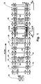
- FIG. 1 shows a top view a accumulation conveyor 10 with a support frame 12, the two parallel to each other, spaced apart and has support walls 14 extending in the conveying direction. Between the support walls 14 are a plurality of parallel to each other aligned and spaced axes 16 mounted on which a plurality of rollers 18 are each freely rotatable. Furthermore, the Accumulation conveyor 10 on a variety of actuators 20, on the if necessary, an endlessly driven traction means 22 over the conveying surface of the Accumulation conveyor 10 can be raised or lowered below this (see Fig. 4). For reasons of clarity, this traction means 22 is not shown in FIG. 1 shown.
- the goods can be driven in the direction of the arrow.
- Lowering the traction device 22 via the actuating elements 20 under the Conveying surface of the rollers 18 requires that the goods to be conveyed on the accumulating conveyor 10 stop and build up.
- the actuators 20 can for example via an elongated element, preferably a rod 24 are driven, which is shifted for this purpose in the conveying direction.
- the pulling means 22 is the rod 24 shift to the left.
- the Actuators 20 formed as a split eccentric cam the are already known from US Pat. No. 3,854,576 and US Pat. No. 4,878,578 and the disclosure of which is hereby incorporated by reference.
- the rod 24 is displaceable in the longitudinal direction over the sensor element in order to Actuating element 20 to start.
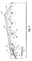
- the sensor element 26 has one Encoder element 28, which is pivotally mounted on an axleless bearing 30 (see Fig. 3).
- the sensor element 28 is provided with a sensor surface 34 Section provided in the conveying path of the conveyed goods along the accumulation conveyor 10 is protruding upward via a biasing element 32.
- the illustrated embodiment is the sensor surface 34 from a pair of finger-like next to each other and with spaced webs, which can be actuated via the parts to be conveyed sliding over them.
- the Finger-like webs of the sensor surface 34 are on an axleless bearing 30, 70 opposite end over an aligned transversely to the conveying direction Connecting element 36 and on the 30,70 facing the axleless bearing End over another connecting element aligned transversely to the conveying direction 38 interconnected to form a frame-like structure (see FIG. 6).
- the axleless bearing 30 is a cutting edge bearing formed, which essentially consists of a pair of lever arms 40 the downward ends of the cutting edges 42 are arranged, which are in support rectangular recesses 44 of the vertical support walls 14.
- the axleless bearing 30 is determined by the downward cutting edges 40, which is on the lower boundary surface 54 in the recess 44 in such a way support that the lever arms 40 seen in the conveying direction forward and backward can commute.
- the encoder element 28 is directed downwards Cutting edges 42 can be pivoted in the recesses 44.
- the Recesses 44 provided an upward opening 46 through which Encoder element 28 with its lever arms 40 inserted into the recess 44 can be.
- the end part 62 is made with a coating 64 damping rubber material surround the noise in the To minimize hook element 60 engaging axis 16.
- a deflecting element 66 is arranged, which is seen in the conveying direction F downward is inclined and the task is to catch the finger-shaped sensor surfaces 34 with conveying parts sliding over them downstream and also enables that parts to be conveyed by hand against the conveying direction via the sensor element 26 can be pushed.
- FIG. 6, which shows a side view of the transmitter element 28 according to FIG. 5
- the distance d is preferably less than about 0.025 m (1 inch) and particularly measures preferred embodiment less than 0.0125 m (one half of an inch). in the In the present exemplary embodiment, the distance d has a dimension of approximately 0.01 m (3/8 of an inch).
- the spring force of Preload element 32 can be designed correspondingly larger.
- the composite spring force of the biasing element 32 at least about 22.5 Newtons (5.0 pounds).
- the Spring force of each of the two spring elements that make up the biasing element 32 approximately 15.7 Newtons (3.5 pounds). This results in a composite spring force of at least about 31.4 Newtons (7.0 pounds).
- the Combination of a short lever arm 40 and a strong pretensioning element has the advantage that the biasing element only by a small amount Total length is cut out when the sensor element 26 of the material to be conveyed is operated. Because the spring force depends on the amount of extension of the Spring varies proportionally, this arrangement results in the spring force being applied by the biasing element 32 is applied, largely the same amount has the entire path of movement of the encoder element 28.
- the sensor element 26 It is therefore possible to apply the sensor element 26 with a vertical force of less than about 4.4 Newtons (one pound) to operate. This force corresponds to that of one empty containers weighing approximately 0.9 kg (two pounds) onto the sensor surface 34 can be applied.
- the sensor element 26 is already actuated with a vertical force of less than about 2.26 Newtons (8 ounces), this corresponds to that of an empty article container with a weight of approximately One pound force applied.
- the sensor element 26 is also suitable actuated by a downward force of approximately 1.8 Newtons (0.4 pounds) become. This force corresponds essentially to that of an empty article container Force applicable with a weight of approximately 0.36 kg (0.6 pound).
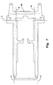
- the transmitter element 28 is advantageously made of a single flat metal sheet 68 can be produced (see FIG. 7).
- the flat metal sheet 68 is along the forming line A crimped at a right angle to arms 56 perpendicular to the sensor surface align and is additionally flanged along the forming lines B and C to the Stiffen finger-shaped sensor surface 34. This creates a mechanical Stiffness of the encoder element 28 is reached and at the same time there is the possibility from the metal sheet 68, the cutting edge 42 of the axleless bearing 30 and the form lateral connecting web 36 and other details of the Encoder element 28.
- the metal sheet 68 punched out and then stiffened by forming and points of attack for Bearings created.
- the encoder element 28 is in via its lever arms 40 Recesses 44 of the vertical support walls 14 of the support frame 12 of the Storage conveyor 10 storable. For their pretensioning, the pretensioning elements 32 fixed between the openings 50 in the support frame 12 and the pins 48. This makes a stable sensor element 26 with a biasing element 32 created that the movable parts of the axleless bearing 30 in their Operating positions.
- Actuators 20 are pneumatic and are controlled by valves, which are actuated by the arms 56 of the transmitter element 28.
- a balanced poppet valve balance poppet valve
- the invention is finger-shaped trained sensor surface 34 provided.
- the sensor surface 34 can be in any state the technology known manner, so that here too Sensor surfaces 34 can be used in the form of rollers. It is also possible instead of the spring elements described tension springs, compression springs or To use torsion springs. A counterweight can also be used as a biasing element be used.
- the present invention also offers the possibility of being placed on the accumulation conveyor 10 withdraw the accumulated goods in a block.
- the operation of the elongated Rod 24 via a movement-damping compression spring 58 enables the Use of piston-cylinder units for driving, such as B. from Pneumatic cylinders to control the actuators from all sections of the To connect the accumulation conveyor.
- the rods can be made independently of the Position of the assigned sensor elements are operated.
- axleless bearing 70 In a further embodiment of the axleless bearing, which is identified by the reference number 70 is shown in FIG. 8.
- the axleless bearing 70 has a flat flexible element 72, which at its lower end 74 in a slot of lower boundary surface of the recess 44 is attached.
- the actuation of the Sensor element 28 causes the flexible element 72 to bend Direction of conveyance to the donor element 28 with respect to the vertical support walls 14 to be able to pivot.
- This axleless bearing 70 has the same advantages like the axleless bearing 30 and namely the low friction and the essential Insensitivity to loads on the storage due to the downward facing Operating forces.
Landscapes
- Engineering & Computer Science (AREA)
- Mechanical Engineering (AREA)
- Control Of Conveyors (AREA)
- Geophysics And Detection Of Objects (AREA)
Description
- Figur 1
- eine Draufsicht auf einen Stauförderer entsprechend der Erfindung,
- Figur 2
- eine Ansicht entlang der Schnittlinie II-II in Figur 1,
- Figur 3
- eine vergrößerte Ansicht entlang der Schnittlinie III-III in Figur 1,
- Figur 4
- eine Ansicht entlang der Schnittlinie IV-IV in Figur 1,
- Figur 5
- eine Seitenansicht eines Geberelementes entsprechend der Erfindung,
- Figur 6
- eine Vorderansicht des Geberelementes gemäß Figur 5,
- Figur 7
- zeigt ein flaches Muster eines Blechteils, das zu einem Geberelement gemäß den Figuren 5 und 6 formbar ist und
- Figur 8
- eine Ansicht gemäß Figur 3 in einer weiteren Ausführungsform der Erfindung.
Claims (21)
- Sensorelement für die Erkennung von Fördergütern auf einer Förderfläche bestehend ausdadurch gekennzeichnet,einem Sensorelement (26) mit einem Geberelement (28),einer Schwenklagerung, über die das Geberelement (28) um eine horizontale Achse schwenkbar ist,und einem Vorspannelement (32), durch das das Sensorelement (28) in eine Stellung zur Erkennung von Fördergut vorspannbar ist,
daß die Schwenklagerung als achslose Lagerung (30,70) ausgebildet ist. - Sensorelement nach Anspruch 1,
dadurch gekennzeichnet,
daß das Vorspannelement (32) als Feder ausgebildet ist, das auf einen Hebelarm (40) wirkt, der an dem Geberelement (28) und außerhalb des Ortes seiner Schwenklagerung angeordnet ist. - Sensorelement nach Anspruch 1 oder 2,
dadurch gekennzeichnet,
daß das Geberelement (28) eine Sensorfläche (34) aufweist, die durch eine Betätigungskraft über einen Betätigungsweg bewegbar ist und der Hebelarm (40) derart ausgebildet ist, daß das Vorspannelement (32) über einen geringeren Weg als der Betätigungsweg bewegbar ist. - Sensorelement nach einem der Ansprüche 1 bis 3,
dadurch gekennzeichnet,
daß die achslose Lagerung (30) als Schneidenlagerung ausgebildet ist, die eine Schneidkante (42) aufweist, die wiegend das Geberelement (28) auf einer Unterlage (Ausnehmung 44) lagert. - Sensorelement nach einem der Ansprüche 1 bis 3,
dadurch gekennzeichnet,
daß die achslose Lagerung (70) im wesentlichen aus einem flexiblen Element (72) besteht, das auf einer Unterlage (Ausnehmung 44) befestigt ist. - Sensorelement nach einem der Ansprüche 1 bis 5,
dadurch gekennzeichnet,
daß das Geberelement (28) und die Schwenklagerung als ein gemeinsames Blechformteil ausgebildet sind. - Sensorelement nach einem der Ansprüche 1 bis 7,
dadurch gekennzeichnet,
daß die Betätigungskraft geringer ist als 4,5 Newton. - Sensorelement nach einem der Ansprüche 1 bis 7,
dadurch gekennzeichnet,
daß die Betätigungskraft geringer ist als 2,3 Newton. - Sensorelement nach einem der Ansprüche 1 bis 8,
dadurch gekennzeichnet,
daß das Vorspannelement (32) eine zusammengesetzte Federkraft von größer als etwa 22,1 Newton aufweist. - Sensorelement nach einem der Ansprüche 1 bis 9,
dadurch gekennzeichnet,
daß das Vorspannelement (32) über einen Hebelarm (40) auf das Geberelement (28) einwirkt und der Hebelarm (40) eine Länge aufweist, die geringer ist als etwa 0,025 m. - Sensorelement nach Anspruch 10,
dadurch gekennzeichnet,
daß der Hebelarm (40) eine Länge von weniger als etwa 0,012 m aufweist. - Stauförderer mit einem Sensorelement (26) nach einem der vorhergehenden Ansprüche 1 bis 8,
dadurch gekennzeichnet,
daß der Stauförderer (10) einen Tragrahmen (12) aufweist, der eine Förderfläche für Fördergüter bildet und ein Betätigungselement (20), das von dem Geberelement (28) zur Steuerung mindestens eines Abschnittes der Förderfläche betätigbar ist. - Stauförderer nach Anspruch 12,
dadurch gekennzeichnet,
daß das Betätigungselement (20) mechanisch über mindestens ein Geberelement (28) betätigbar ist. - Stauförderer nach Anspruch 13,
dadurch gekennzeichnet,
daß mindestens ein Geberelement (28) eine Sensorfläche (34) aufweist und das Betätigungselement (20) mechanisch über eine Stange (24), die sich ausgehend von der Sensorfläche (24) erstreckt, betätigbar ist. - Stauförderer nach Anspruch 14,
dadurch gekennzeichnet,
daß die Sensorfläche (34) über eine zusammendrückbares Element mit der Stange (24) verbunden ist. - Stauförderer nach Anspruch 15,
dadurch gekennzeichnet,
daß zusammendrückbare Element eine Feder (58) ist. - Stauförderer nach Anspruch 12,
dadurch gekennzeichnet,
daß das Betätigungselement (20) über mindestens ein Sensorelement (26) pneumatisch betätigbar ist. - Stauförderer nach Anspruch 16,
dadurch gekennzeichnet,
daß das Geberelement (26) eine Sensorfläche (34) aufweist, und das Betätigungselement (20) pneumatisch über ein Ventil betätigbar ist, das von der Sensorfläche (34) betätigbar ist. - Stauförderer nach Anspruch 18,
dadurch gekennzeichnet,
daß Ventil ein ausbalanciertes Tellerventil ist. - Stauförderer nach einem der Ansprüche 11 bis 19 sowie 4 oder 5,
dadurch gekennzeichnet,
daß die Unterlage der Schwenklagerung als Ausnehmung (44) in dem Tragrahmen (12) ausgebildet ist. - Stauförderer nach Anspruch 20,
dadurch gekennzeichnet,
daß das Vorspannelement (32) das Geberelement in Richtung unterer Begrenzungsfläche (54) der Ausnehmung (44) vorspannt.
Applications Claiming Priority (3)
| Application Number | Priority Date | Filing Date | Title |
|---|---|---|---|
| US664308 | 1996-06-11 | ||
| US08/664,308 US5810154A (en) | 1996-06-11 | 1996-06-11 | Low actuation force article sensor for conveyor |
| PCT/DE1997/001204 WO1997047542A1 (de) | 1996-06-11 | 1997-06-10 | Mechanisches sensorelement für fördergut auf einem förderer |
Publications (2)
| Publication Number | Publication Date |
|---|---|
| EP0912428A1 EP0912428A1 (de) | 1999-05-06 |
| EP0912428B1 true EP0912428B1 (de) | 2000-03-01 |
Family
ID=24665469
Family Applications (1)
| Application Number | Title | Priority Date | Filing Date |
|---|---|---|---|
| EP97930315A Expired - Lifetime EP0912428B1 (de) | 1996-06-11 | 1997-06-10 | Mechanisches sensorelement für fördergut auf einem förderer |
Country Status (10)
| Country | Link |
|---|---|
| US (1) | US5810154A (de) |
| EP (1) | EP0912428B1 (de) |
| JP (1) | JP2000511858A (de) |
| AT (1) | ATE190036T1 (de) |
| AU (1) | AU717694B2 (de) |
| BR (1) | BR9709686A (de) |
| CA (1) | CA2256320A1 (de) |
| DE (1) | DE59701189D1 (de) |
| ES (1) | ES2143315T3 (de) |
| WO (1) | WO1997047542A1 (de) |
Families Citing this family (5)
| Publication number | Priority date | Publication date | Assignee | Title |
|---|---|---|---|---|
| US6848567B2 (en) * | 2001-11-16 | 2005-02-01 | Alvey Systems, Inc. | Accumulation conveyor |
| US7993088B2 (en) * | 2005-03-09 | 2011-08-09 | The Kroger Co. | Storage system having a dynamic support of moving elements and a pusher assembly carried by a frame |
| US7722307B2 (en) * | 2004-09-03 | 2010-05-25 | Daifuku America Corporation | System and method for handling stocked items |
| US9833962B2 (en) * | 2014-02-26 | 2017-12-05 | Toyota Motor Engineering & Manufacturing Norh America, Inc. | Systems and methods for controlling manufacturing processes |
| US9420900B1 (en) * | 2015-01-29 | 2016-08-23 | Toyota Motor Engineering & Manufacturing North America, Inc. | Mobile inventory rack apparatus and inventory rack system |
Family Cites Families (47)
| Publication number | Priority date | Publication date | Assignee | Title |
|---|---|---|---|---|
| US1934707A (en) * | 1927-04-04 | 1933-11-14 | Herman L Hartenstein | Manufacture of fertilizer |
| US2785785A (en) * | 1955-05-05 | 1957-03-19 | Ballantine & Sons P | Roller conveyor apparatus |
| US3000489A (en) * | 1959-05-29 | 1961-09-19 | Rapids Standard Co Inc | Sensing device |
| US3115238A (en) * | 1961-02-06 | 1963-12-24 | Standard Conveyor Co | Conveyor belt actuators |
| US3116823A (en) * | 1962-06-26 | 1964-01-07 | Rapids Standard Co Inc | Power erected accumulator |
| US3206008A (en) * | 1963-08-29 | 1965-09-14 | Rapids Standard Co Inc | Accumulative-type conveyor structure |
| US3269522A (en) * | 1964-10-23 | 1966-08-30 | Rapids Standard Co Inc | Heavy duty accumulator |
| US3321057A (en) * | 1966-04-25 | 1967-05-23 | Rapids Standard Co Inc | Retarder for gravity conveyor |
| US3420355A (en) * | 1966-10-20 | 1969-01-07 | Rapistan Inc | Accumulator conveyor with pneumatic delay |
| US3621982A (en) * | 1969-01-24 | 1971-11-23 | Gen Logistics | Self-energizing brake for roller conveyors |
| US3826349A (en) * | 1970-05-06 | 1974-07-30 | C Stevenson | Live storage conveyor system |
| US3770102A (en) * | 1971-07-30 | 1973-11-06 | Good M De | Accumulator with transport override |
| US3724642A (en) * | 1971-07-30 | 1973-04-03 | Rapistan Inc | Accumulator with braking |
| US3730330A (en) * | 1971-08-06 | 1973-05-01 | Rapistan Inc | Sensor locking accumulator |
| US3768630A (en) * | 1971-11-16 | 1973-10-30 | Rapistan Inc | Accumulator with automatic override |
| US3840110A (en) * | 1972-07-24 | 1974-10-08 | Ermanco Inc | Conveyor apparatus |
| US4103769A (en) * | 1976-07-06 | 1978-08-01 | Stone Conveyor, Inc. (Entire) | Live roller conveyor |
| US4109783A (en) * | 1976-08-02 | 1978-08-29 | The E. W. Buschman Company | Fluid control circuit and method for an accumulator conveyor |
| DE2650205C2 (de) * | 1976-11-02 | 1984-08-02 | Richard 6920 Sinsheim Gebhardt | Staurollenbahn zum Fördern und drucklosen Stauen von Stückgut |
| US4301914A (en) * | 1977-09-09 | 1981-11-24 | Sandard Conveyor Company | Accumulating conveyor |
| US4174777A (en) * | 1978-02-24 | 1979-11-20 | A-T-O Inc. | Zero pressure accumulating conveyor and method |
| US4202440A (en) * | 1978-04-28 | 1980-05-13 | Nagoya Kiko Kabushiki Kaisha | Apparatus for accumulating materials on a shuttle conveyor |
| US4278166A (en) * | 1978-06-23 | 1981-07-14 | Pirro Jr Michael S | Accumulator conveyor |
| US4223780A (en) * | 1978-09-01 | 1980-09-23 | Rapistan Incorporated | Accumulation conveyors |
| US4212385A (en) * | 1978-09-29 | 1980-07-15 | Leach John M | Article accumulation conveyor |
| DE2853483C2 (de) * | 1978-12-12 | 1985-08-29 | geb. Kramer Elfriede 6920 Sinsheim Gebhardt | Stauförderer für Stückgut |
| NL7903711A (nl) * | 1979-05-11 | 1980-11-13 | Rapistan Van Der Lande Bv | Transportinrichting. |
| US4453627A (en) * | 1980-02-08 | 1984-06-12 | The E. W. Buschman Co. | Accumulator conveyor |
| US4362238A (en) * | 1980-04-10 | 1982-12-07 | Mid-West Conveyor Company | Selective drive arrangement for roller conveyor |
| US4353458A (en) * | 1980-05-09 | 1982-10-12 | Lear Siegler, Inc. | Belt supports for accumulators |
| JPS60900B2 (ja) * | 1980-06-13 | 1985-01-10 | 積水化学工業株式会社 | 接着剤被覆用クロスヘツドダイ |
| US4361225A (en) * | 1980-09-18 | 1982-11-30 | Lear Siegler, Inc. | Actuator belt accumulator |
| US4441607A (en) * | 1981-09-04 | 1984-04-10 | Lear Siegler, Inc. | Mode changing means for accumulator conveyors |
| DE3202382C2 (de) * | 1982-01-26 | 1984-01-05 | Gebhardt Fördertechnik GmbH, 6920 Sinsheim | Reversierbare Stauförderbahn |
| US5042644A (en) * | 1982-01-27 | 1991-08-27 | Ermanco Incorporated | Zero pressure accumulation conveyor and trigger assembly |
| US4488638A (en) * | 1982-05-27 | 1984-12-18 | Figgie International Inc. | Live roller accumulating brake conveyor |
| US4817784A (en) * | 1982-05-27 | 1989-04-04 | Figgie International Inc. | Zero pressure accumulating conveyor control |
| US4473148A (en) * | 1982-09-17 | 1984-09-25 | Lear Siegler, Inc. | Motion sensor for motion sensing accumulator |
| US4542815A (en) * | 1983-11-03 | 1985-09-24 | Lear Siegler, Inc. | Air brake and retarder for gravity conveyors |
| US4605120A (en) * | 1983-11-29 | 1986-08-12 | Mid-West Conveyor Company, Inc. | Shaft driven accumulation conveyor arrangement |
| US4588073A (en) * | 1984-09-26 | 1986-05-13 | Alvey Inc. | Padded chain live roller conveyor |
| US4658951A (en) * | 1985-02-27 | 1987-04-21 | Saunders Stanley S | Reciprocating transfer conveyor with sensing accumulating pads |
| JPH0678254B2 (ja) * | 1985-07-09 | 1994-10-05 | 三井東圧化学株式会社 | 6,6′−ジヒドロキシ−3,3,3′,3′−テトラメチル−1,1′−スピロビインダンの製造方法 |
| US4854445A (en) * | 1985-11-12 | 1989-08-08 | Figgie International Inc. | Wide range accumulator conveyor |
| US5016748A (en) * | 1989-07-10 | 1991-05-21 | Automotion, Incorporated | Accumulating conveyor |
| US5358097A (en) * | 1990-10-30 | 1994-10-25 | Rapistan Demag Corporation | Accumulation conveyor with retractable sensor |
| US5429225A (en) * | 1990-10-30 | 1995-07-04 | Rapistan Demag Corporation | Modular pneumatic accumulation conveyor and method |
-
1996
- 1996-06-11 US US08/664,308 patent/US5810154A/en not_active Expired - Fee Related
-
1997
- 1997-06-10 JP JP10501073A patent/JP2000511858A/ja active Pending
- 1997-06-10 WO PCT/DE1997/001204 patent/WO1997047542A1/de not_active Ceased
- 1997-06-10 DE DE59701189T patent/DE59701189D1/de not_active Expired - Fee Related
- 1997-06-10 EP EP97930315A patent/EP0912428B1/de not_active Expired - Lifetime
- 1997-06-10 BR BR9709686A patent/BR9709686A/pt not_active IP Right Cessation
- 1997-06-10 AU AU34330/97A patent/AU717694B2/en not_active Ceased
- 1997-06-10 ES ES97930315T patent/ES2143315T3/es not_active Expired - Lifetime
- 1997-06-10 AT AT97930315T patent/ATE190036T1/de not_active IP Right Cessation
- 1997-06-10 CA CA002256320A patent/CA2256320A1/en not_active Abandoned
Also Published As
| Publication number | Publication date |
|---|---|
| BR9709686A (pt) | 1999-08-10 |
| EP0912428A1 (de) | 1999-05-06 |
| AU717694B2 (en) | 2000-03-30 |
| WO1997047542A1 (de) | 1997-12-18 |
| CA2256320A1 (en) | 1997-12-18 |
| JP2000511858A (ja) | 2000-09-12 |
| AU3433097A (en) | 1998-01-07 |
| US5810154A (en) | 1998-09-22 |
| DE59701189D1 (de) | 2000-04-06 |
| ATE190036T1 (de) | 2000-03-15 |
| ES2143315T3 (es) | 2000-05-01 |
Similar Documents
| Publication | Publication Date | Title |
|---|---|---|
| DE2704045C3 (de) | Vorrichtung zum Verhindern von Doppelabzügen | |
| EP3248913A1 (de) | Singulationsförderer und verfahren zum fördern und vereinzeln von stückgut entlang wenigstens einer transportbahn | |
| EP0912428B1 (de) | Mechanisches sensorelement für fördergut auf einem förderer | |
| EP3878775A1 (de) | Rollenbahn mit bremsvorrichtung | |
| DE68906665T2 (de) | Zweirichtungs-Fahrvorrichtung zum seitlichen Sortieren von Gegenständen in Transportsystemen mit flexibler Bahn. | |
| DE29711710U1 (de) | Durchlaufregal zum Kommissionieren | |
| EP3580534B1 (de) | Förder- und dosiereinrichtung | |
| WO2022122792A2 (de) | Ausschleusvorrichtung | |
| DE19525635C2 (de) | Vorrichtung zur Bogenauslage in einer Bogendruckmaschine | |
| EP0180710A2 (de) | Transportvorrichtung für Stückgüter oder dergleichen | |
| DE102004014443A1 (de) | Fördereinrichtung mit einer Weiche | |
| DE3235756A1 (de) | Stetigfoerderer, insbesondere tragkettenfoerderer | |
| CH687421A5 (de) | Praezisionswaage. | |
| DE3337552C2 (de) | ||
| EP0308688A2 (de) | Rundstapelbogenanleger | |
| DE3237599C2 (de) | ||
| DE4212833A1 (de) | Vorrichtung zum trennen duenner und flacher gegenstaende, wie z. b. kartonzuschnitte, die aufeinanderfolgend in kontinuierlicher reihe auf wenigstens einer transportvorrichtung bewegt werden | |
| EP0514809B1 (de) | Förderanlage für als Stückgut ausgebildetes Fördergut | |
| DE19513422C2 (de) | Staurollenbahn | |
| DE19641161C2 (de) | Deckbandförderer | |
| EP4045438B1 (de) | Antriebsvorrichtung für einen förderwagen einer fördereinrichtung | |
| DE102024114464A1 (de) | Rollenbahn zur führung von mehreren hintereinander angeordneten lagereinheiten | |
| DE19623979A1 (de) | Girlanden-Tragrollensatz | |
| DE20110929U1 (de) | Fördereinrichtung mit Förderkette | |
| EP1218271A1 (de) | Vorrichtung zum drehen eines papierstapels |
Legal Events
| Date | Code | Title | Description |
|---|---|---|---|
| PUAI | Public reference made under article 153(3) epc to a published international application that has entered the european phase |
Free format text: ORIGINAL CODE: 0009012 |
|
| 17P | Request for examination filed |
Effective date: 19981123 |
|
| AK | Designated contracting states |
Kind code of ref document: A1 Designated state(s): AT CH DE DK ES FR GB IT LI NL |
|
| GRAG | Despatch of communication of intention to grant |
Free format text: ORIGINAL CODE: EPIDOS AGRA |
|
| GRAG | Despatch of communication of intention to grant |
Free format text: ORIGINAL CODE: EPIDOS AGRA |
|
| GRAH | Despatch of communication of intention to grant a patent |
Free format text: ORIGINAL CODE: EPIDOS IGRA |
|
| 17Q | First examination report despatched |
Effective date: 19990716 |
|
| GRAH | Despatch of communication of intention to grant a patent |
Free format text: ORIGINAL CODE: EPIDOS IGRA |
|
| GRAA | (expected) grant |
Free format text: ORIGINAL CODE: 0009210 |
|
| AK | Designated contracting states |
Kind code of ref document: B1 Designated state(s): AT CH DE DK ES FR GB IT LI NL |
|
| REF | Corresponds to: |
Ref document number: 190036 Country of ref document: AT Date of ref document: 20000315 Kind code of ref document: T |
|
| ET | Fr: translation filed | ||
| REG | Reference to a national code |
Ref country code: CH Ref legal event code: NV Representative=s name: E. BLUM & CO. PATENTANWAELTE Ref country code: CH Ref legal event code: EP |
|
| GBT | Gb: translation of ep patent filed (gb section 77(6)(a)/1977) |
Effective date: 20000301 |
|
| REF | Corresponds to: |
Ref document number: 59701189 Country of ref document: DE Date of ref document: 20000406 |
|
| ITF | It: translation for a ep patent filed | ||
| REG | Reference to a national code |
Ref country code: ES Ref legal event code: FG2A Ref document number: 2143315 Country of ref document: ES Kind code of ref document: T3 |
|
| REG | Reference to a national code |
Ref country code: DK Ref legal event code: T3 |
|
| PLBE | No opposition filed within time limit |
Free format text: ORIGINAL CODE: 0009261 |
|
| STAA | Information on the status of an ep patent application or granted ep patent |
Free format text: STATUS: NO OPPOSITION FILED WITHIN TIME LIMIT |
|
| 26N | No opposition filed | ||
| REG | Reference to a national code |
Ref country code: GB Ref legal event code: IF02 |
|
| PGFP | Annual fee paid to national office [announced via postgrant information from national office to epo] |
Ref country code: AT Payment date: 20030514 Year of fee payment: 7 |
|
| PGFP | Annual fee paid to national office [announced via postgrant information from national office to epo] |
Ref country code: GB Payment date: 20030611 Year of fee payment: 7 |
|
| PGFP | Annual fee paid to national office [announced via postgrant information from national office to epo] |
Ref country code: DK Payment date: 20030612 Year of fee payment: 7 |
|
| PGFP | Annual fee paid to national office [announced via postgrant information from national office to epo] |
Ref country code: NL Payment date: 20030619 Year of fee payment: 7 |
|
| PGFP | Annual fee paid to national office [announced via postgrant information from national office to epo] |
Ref country code: ES Payment date: 20030626 Year of fee payment: 7 |
|
| PGFP | Annual fee paid to national office [announced via postgrant information from national office to epo] |
Ref country code: FR Payment date: 20030627 Year of fee payment: 7 |
|
| PGFP | Annual fee paid to national office [announced via postgrant information from national office to epo] |
Ref country code: DE Payment date: 20030818 Year of fee payment: 7 |
|
| PGFP | Annual fee paid to national office [announced via postgrant information from national office to epo] |
Ref country code: CH Payment date: 20030905 Year of fee payment: 7 |
|
| PG25 | Lapsed in a contracting state [announced via postgrant information from national office to epo] |
Ref country code: GB Free format text: LAPSE BECAUSE OF NON-PAYMENT OF DUE FEES Effective date: 20040610 Ref country code: AT Free format text: LAPSE BECAUSE OF NON-PAYMENT OF DUE FEES Effective date: 20040610 |
|
| PG25 | Lapsed in a contracting state [announced via postgrant information from national office to epo] |
Ref country code: ES Free format text: LAPSE BECAUSE OF NON-PAYMENT OF DUE FEES Effective date: 20040611 |
|
| PG25 | Lapsed in a contracting state [announced via postgrant information from national office to epo] |
Ref country code: LI Free format text: LAPSE BECAUSE OF NON-PAYMENT OF DUE FEES Effective date: 20040630 Ref country code: DK Free format text: LAPSE BECAUSE OF NON-PAYMENT OF DUE FEES Effective date: 20040630 Ref country code: CH Free format text: LAPSE BECAUSE OF NON-PAYMENT OF DUE FEES Effective date: 20040630 |
|
| PG25 | Lapsed in a contracting state [announced via postgrant information from national office to epo] |
Ref country code: NL Free format text: LAPSE BECAUSE OF NON-PAYMENT OF DUE FEES Effective date: 20050101 Ref country code: DE Free format text: LAPSE BECAUSE OF NON-PAYMENT OF DUE FEES Effective date: 20050101 |
|
| REG | Reference to a national code |
Ref country code: DK Ref legal event code: EBP |
|
| GBPC | Gb: european patent ceased through non-payment of renewal fee |
Effective date: 20040610 |
|
| REG | Reference to a national code |
Ref country code: CH Ref legal event code: PL |
|
| PG25 | Lapsed in a contracting state [announced via postgrant information from national office to epo] |
Ref country code: FR Free format text: LAPSE BECAUSE OF NON-PAYMENT OF DUE FEES Effective date: 20050228 |
|
| NLV4 | Nl: lapsed or anulled due to non-payment of the annual fee |
Effective date: 20050101 |
|
| REG | Reference to a national code |
Ref country code: FR Ref legal event code: ST |
|
| PG25 | Lapsed in a contracting state [announced via postgrant information from national office to epo] |
Ref country code: IT Free format text: LAPSE BECAUSE OF NON-PAYMENT OF DUE FEES;WARNING: LAPSES OF ITALIAN PATENTS WITH EFFECTIVE DATE BEFORE 2007 MAY HAVE OCCURRED AT ANY TIME BEFORE 2007. THE CORRECT EFFECTIVE DATE MAY BE DIFFERENT FROM THE ONE RECORDED. Effective date: 20050610 |
|
| REG | Reference to a national code |
Ref country code: ES Ref legal event code: FD2A Effective date: 20040611 |