EP0912794B1 - Classeur cylindrique et procede de production correspondant - Google Patents
Classeur cylindrique et procede de production correspondant Download PDFInfo
- Publication number
- EP0912794B1 EP0912794B1 EP97952160A EP97952160A EP0912794B1 EP 0912794 B1 EP0912794 B1 EP 0912794B1 EP 97952160 A EP97952160 A EP 97952160A EP 97952160 A EP97952160 A EP 97952160A EP 0912794 B1 EP0912794 B1 EP 0912794B1
- Authority
- EP
- European Patent Office
- Prior art keywords
- screen
- plate
- flow deflecting
- cylindrical
- grooves
- Prior art date
- Legal status (The legal status is an assumption and is not a legal conclusion. Google has not performed a legal analysis and makes no representation as to the accuracy of the status listed.)
- Revoked
Links
- 238000000034 method Methods 0.000 title claims description 10
- 239000000725 suspension Substances 0.000 claims abstract description 24
- 239000002245 particle Substances 0.000 claims abstract description 20
- 238000012216 screening Methods 0.000 claims abstract description 13
- 238000000926 separation method Methods 0.000 claims abstract description 6
- 229920001131 Pulp (paper) Polymers 0.000 claims abstract description 4
- 238000003754 machining Methods 0.000 claims description 5
- 239000000463 material Substances 0.000 claims description 5
- 238000005452 bending Methods 0.000 claims description 4
- XLYOFNOQVPJJNP-UHFFFAOYSA-N water Substances O XLYOFNOQVPJJNP-UHFFFAOYSA-N 0.000 claims description 4
- 238000003698 laser cutting Methods 0.000 claims description 3
- 239000007787 solid Substances 0.000 claims description 2
- 230000002542 deteriorative effect Effects 0.000 abstract 1
- 239000000356 contaminant Substances 0.000 description 2
- 230000008878 coupling Effects 0.000 description 2
- 238000010168 coupling process Methods 0.000 description 2
- 238000005859 coupling reaction Methods 0.000 description 2
- 230000007423 decrease Effects 0.000 description 2
- 238000007599 discharging Methods 0.000 description 1
- 230000002349 favourable effect Effects 0.000 description 1
- 238000003801 milling Methods 0.000 description 1
- 238000010408 sweeping Methods 0.000 description 1
Images


Classifications
-
- D—TEXTILES; PAPER
- D21—PAPER-MAKING; PRODUCTION OF CELLULOSE
- D21D—TREATMENT OF THE MATERIALS BEFORE PASSING TO THE PAPER-MAKING MACHINE
- D21D5/00—Purification of the pulp suspension by mechanical means; Apparatus therefor
- D21D5/02—Straining or screening the pulp
- D21D5/16—Cylinders and plates for screens
-
- D—TEXTILES; PAPER
- D21—PAPER-MAKING; PRODUCTION OF CELLULOSE
- D21D—TREATMENT OF THE MATERIALS BEFORE PASSING TO THE PAPER-MAKING MACHINE
- D21D5/00—Purification of the pulp suspension by mechanical means; Apparatus therefor
- D21D5/02—Straining or screening the pulp
-
- B—PERFORMING OPERATIONS; TRANSPORTING
- B01—PHYSICAL OR CHEMICAL PROCESSES OR APPARATUS IN GENERAL
- B01D—SEPARATION
- B01D29/00—Filters with filtering elements stationary during filtration, e.g. pressure or suction filters, not covered by groups B01D24/00 - B01D27/00; Filtering elements therefor
- B01D29/11—Filters with filtering elements stationary during filtration, e.g. pressure or suction filters, not covered by groups B01D24/00 - B01D27/00; Filtering elements therefor with bag, cage, hose, tube, sleeve or like filtering elements
- B01D29/13—Supported filter elements
- B01D29/23—Supported filter elements arranged for outward flow filtration
- B01D29/25—Supported filter elements arranged for outward flow filtration open-ended the arrival of the mixture to be filtered and the discharge of the concentrated mixture are situated on both opposite sides of the filtering element
-
- B—PERFORMING OPERATIONS; TRANSPORTING
- B01—PHYSICAL OR CHEMICAL PROCESSES OR APPARATUS IN GENERAL
- B01D—SEPARATION
- B01D29/00—Filters with filtering elements stationary during filtration, e.g. pressure or suction filters, not covered by groups B01D24/00 - B01D27/00; Filtering elements therefor
- B01D29/44—Edge filtering elements, i.e. using contiguous impervious surfaces
- B01D29/445—Bar screens
-
- B—PERFORMING OPERATIONS; TRANSPORTING
- B01—PHYSICAL OR CHEMICAL PROCESSES OR APPARATUS IN GENERAL
- B01D—SEPARATION
- B01D29/00—Filters with filtering elements stationary during filtration, e.g. pressure or suction filters, not covered by groups B01D24/00 - B01D27/00; Filtering elements therefor
- B01D29/76—Handling the filter cake in the filter for purposes other than for regenerating
- B01D29/86—Retarding cake deposition on the filter during the filtration period, e.g. using stirrers
-
- B—PERFORMING OPERATIONS; TRANSPORTING
- B01—PHYSICAL OR CHEMICAL PROCESSES OR APPARATUS IN GENERAL
- B01D—SEPARATION
- B01D2201/00—Details relating to filtering apparatus
- B01D2201/18—Filters characterised by the openings or pores
- B01D2201/184—Special form, dimension of the openings, pores of the filtering elements
Definitions
- the present invention relates to a cylindrical screen with an inlet side and an outlet side for the kind of pressure screening device which is intended for separating undesired particles from paper pulp suspensions and which has a rotor with a number of rotor wings adapted to move along a cylindrical path, which is coaxial with the cylindrical screen and which extends quite close to the inlet side of the screen.
- the screen comprises an axial inlet end at the inlet side for receiving the suspension to be separated, an axial reject end at the inlet side for removing separated particles, elongated flow deflecting members, which are arranged at the inlet side of the screen and which are distributed around the circumference of the screen, and screen holes arranged between the flow deflecting members.
- Each elongated flow deflecting member extends obliquely relative to the centre axis of the cylindrical screen and forwards relative to the direction of rotation of said rotor wings as seen from the inlet end of the screen towards the reject end of the screen, whereby during operation, when the screen is mounted in said pressure screening device, the flow deflecting members deflect the suspension flow containing separated particles entrained by said rotor wings along said cylindrical path, so that the suspension flow gets a component of movement towards the reject end of the screen.
- the invention also relates to a method of producing such a cylindrical screen.
- said oblique flow deflecting members of a conventional screen of this kind efficiently promotes rapid transportation of separated particles towards the reject end of the screen, since each time a particle is passed by a rotor wing it is subjected to a pulse, which means that the particle runs the risk of being turned so that it may pass through a screen hole.
- the efficiency of the screen with respect to separation of undesired particles decreases therefore with increasing number of pulses that each particle is subjected to.
- the capacity of the screen depends on the number of screen holes arranged per surface unit, i.e. how large an open area the screen has.
- the open area of the screen is, however, limited by reasons of strength (the more screen holes the weaker screen) and by the number of flow deflecting members (more flow deflecting members means room for fewer screen holes). If the open area is made relatively large at the expense of fewer flow deflecting members the problem arises, however, that the efficiency of the screen with respect to separation of undesired particles is reduced.
- EP-B-0 046 687 discloses a screen, which comprises a cylindrical plate of uniform thickness and which in one embodiment is provided with oblique flow deflecting members in the form of bars, which are welded on the inlet side of the screen. Between adjacent bars there are a plurality of screen holes distributed in the circumferencial direction of the screen. It is mentioned that the distance between adjacent bars may be varied from 6.35 to 127 mm, in particuler from 12.7 to 127 mm.
- the object of the present invention is to provide a cylindrical screen for pressure screening apparatuses and having an improved efficiency with respect to separation of undesired particles without the capacity being reduced, as compared with conventional screens.
- a screen of the kind initially stated which is characterized in that the distance between adjacent operative flow deflecting members as seen in the circumferential direction of the screen is less than six millimeters.
- a screen with many flow deflecting members is obtained, which gives a high efficiency with respect to separation of undesired particles.
- the short distance between adjacent flow deflecting members permits room for only one or possibly two screen holes between said members as seen in the circumferential direction of the cylindrical screen, which gives the advantage that the screen holes are efficiently cleansed from plugging fibres, as the rotor wings pass the screen holes.
- the efficient cleansing of the screen holes is due to that the pulse from a passing rotor wing creates a strong local turbulence in the narrow area between adjacent flow deflecting members, which uncovers the screen holes from possibly plugging fibres.
- the theoretical reduced open area of the screen which is due to the great number of flow deflecting members, is thus surprisingly compensated by said strong local turbulence which arises during operation and which in practice gives at least as large an open area of the screen according to the invention as that of conventional screens with fewer flow deflecting members and more screen holes.
- the pulse frequency from the rotor wings increases with increasing number of flow deflecting members, which contributes to maintain the screen holes uncovered.
- Each elongated flow deflecting member preferably forms an angle to a generatrix to the cylindrical screen which is in the range of 1-40° and which may be constant.
- Each flow deflecting member may advantageously form an angle to said generatrix relatively close to the reject end of the screen which is larger than the angle each flow deflecting member forms with said generatrix relatively close to the inlet end of the screen.
- the flow deflecting members will give the suspension flow a larger component of movement towards the reject end of the screen relatively close to the reject end of the screen, where the share of undesired particles in the suspension is relatively large, than relatively close to the inlet end of the screen.
- Each flow deflecting member may be arranged such that said angle increases stepwise or continuously when the generatrix is moved so that the intersection point between said members and the generatrix is moved in the direction towards the reject end of the screen.
- the screen is formed by a plane plate of uniform thickness, which is bent to cylindrical shape.
- a multiplicity of elongated parallel grooves are formed in the plate on the inlet side of the screen by material reducing machining of the plate, the screen holes of the screen opening in said grooves.
- the grooves are confined by elongated wall surfaces which constitute said flow deflecting members. Said wall surfaces comprise two opposite wall surfaces along each groove, and therefore it is realized that during operation one of said two opposite wall surfaces will be operative as a flow deflecting member of the kind here intended, to affect the suspension flow so that it will get a component of movement towards the reject end of the screen.
- the screen holes may suitably be oriented in rows, one single row of screen holes extending between adjacent flow deflecting members.
- the screen is formed by a multiplicity of separate elongated solid wall elements arranged in a circular row. Adjacent wall elements extend in parallel with and at a small distance from each other, so that an elongated gap is formed between them and constitutes one of said screen holes. On the inlet side of the screen adjacent wall elements form grooves which are confined by elongated wall surfaces, which constitute said flow deflecting members.
- a further object of the present invention is to provide a simple method of producing a cylindrical screen of the kind here present.
- a method which comprises the steps of: a) forming a multiplicity of elongated parallel grooves on one side of a plane plate of uniform thickness by material reducing machining of the plate; b) forming screen holes in the plane plate in the area of each groove by machine cutting of the plate, so that the screen holes extend from the grooves and diverge towards the opposite side of the plate, and c) bending the plate to a cylindrical shape, so that the grooves are on the intremal side of the cylindrical plate characterized in that said screen holes are formed in the plane plate such that they extend from said grooves and diverge towards the opposite side of the plate, that said grooves are formed such that ridges are left on both sides of every groove, forming flow deflecting members on the completed screen, the distance between the formed flow deflecting members being less than six millimeters in the circumferential direction of the screen, and that the screen is formed such that said grooves extend obliquely relative to the centre axis of the cylindrical plate when the plate has been bent to cylindrical shape
- the openings of the screen holes on the internal side of the cylindrical screen will be thinner as compared to the corresponding openings on the original plane plate, which gives the advantage that particularly thin inlet openings can be formed even by means of relatively coarse but reliable cutting tools.
- the plane plate may be rectangular and the elongated grooves may be formed so that they extend obliquely relative to the side edges of the plate. Then, the plate may be bent to its cylindrical shape so that two of the opposite edges of the plate abut each other, whereby the grooves extend obliquely relative to the centre axis of the cylindrical plate. As an alternative, the plate may initially be provided with the grooves and then be cut to rectangular shape, so that the grooves extend obliquely relative to the side edges of the plate.
- Each screen hole may be formed by laser cutting by means of a laser beam which cuts through the plane plate from said opposite side of the plate.
- the laser beam suitably has an axial cross-section which converge through the plate in the direction from said one side of the plate. As a result, diverging screen holes are obtained with the aid of one single laser beam.
- each screen hole may be formed by water cutting.
- FIG 1 there is shown a conventional pressure screening apparatus comprising a hollow housing 1, a stationary circular cylindrical screen 2, which extends within the housing 1 and which divides the interior of the housing 1 into a chamber 3 for pulp suspension to be screened by the screen 2 and an annular chamber 4 for receiving screened pulp suspension.
- a rotor 5 is journalled in the housing 1 by means of a bearing 6 and extends in the interior of the screen 2, the rotor 5 being rotatable by a drive motor 7 about an axis 8 which is coaxial with the screen 2.
- the rotor 5 is provided with four rotor wings 9 (more or less than four rotor wings may however be arranged), which extend axially along the rotor 5 and at a small distance from the screen 2. The purpose of the rotor wings 9 is to prevent clogging of the screen holes of the screen 2 and to maintain a flow of suspension in the circumferential direction of the screen.
- the chamber 3 has an inlet 10 for supplying pulp suspension to be separated to an axial inlet end 11 of the screen 2 and a reject outlet 12 for discharging separated contaminants from an axial outlet end 13 of the screen 2.
- a valve 14 for adjusting the reject flow.
- the annular chamber 4 has an accept outlet 15 for separated suspension.
- FIG 2 there is shown a cylindrical screen 16 according to a preferred embodiment of the invention intended to be used in the pressure screening apparatus according to figure 1.
- the screen 16 comprises four separate cylindrical screen elements 17-20, which are releasably coupled to each other by means of annular coupling members 21.
- the screen 16 may be formed in one single piece. Since the screen 16 is worn faster at the reject end 13 than at the inlet end 11 the screen 16 can be renovated at a low price by exchanging only the screen element 20 which is located closest to the reject end 13 by a new one.
- the screen 16 may be adapted to different operation conditions by coupling together screen elements 17-20 with different screen hole patterns and/or different arrangements of flow deflecting members.
- each screen element 17-20 has a multiplicity of elongated flow deflecting members 22 distributed around the circumference of the screen 16, the distance between adjacent operative flow deflecting members 22 as seen in the circumferential direction of the screen 16 being less than 6 mm.
- Each member 22 extends obliquely relative to the centre axis 23 of the screen and forwards relative to the direction of rotation of the rotor wings 9 as seen from the inlet end 11 of the screen 16 towards the reject end 13 of the screen 16. Between adjacent members 22 there are screen holes in the form of slots 23.
- the drive motor 7 drives the rotor 5 so that the rotor wings 9 move along a relatively thin cylindrical path, which is coaxial with the screen 16 and which extends close to the inlet side of the screen 16, here the internal side of the screen 16.
- the suspension flow containing separated undesired particles that are entrained by the rotor wings 9 along the cylindrical path is deflected by the obliquely arranged flow deflecting members 22, so that the suspension flow gets a component of movement towards the reject end 13 of the screen 16.
- Each flow deflecting member 22 of the screen according to the invention forms an angle a to the generatrix G to the cylindrical screen which should be at least 1° and maximally 40°.
- the angle a is constant regardless of where on the screen 16 said generatrix G intersects a flow deflecting member 22, which is schematically shown in figure 3.
- each flow deflecting member (24 and 25 in figure 4 and 5, respectively) may form an angle (b1 and c1 in figure 4 and 5, respectively) to the generatrix G relatively close to the reject end 13 of the screen which is greater than the angle (b2 and c2 in figure 4 and 5, respectively) which each flow deflecting member forms to the generatrix G relatively close to the inlet end 11 of the screen.
- the suspension flow in said cylindrical path is given a greater component of movement towards the reject end of the screen the closer the flow is to the reject end of the screen.
- This is favourable to the efficiency of the screen with respect to separated contaminants, since the share of fibres in the suspension in the interior of the screen decreases from the inlet end of the screen to the reject end of the screen, and therefore it is more important to promote the axial transportation of the suspension close to the reject end than to separate fibres through the screen.
- each flow deflecting member may be arranged so that it forms an angle b1, b2 which increases continuously (figure 4) or forms an angle c1, c2 which increases stepwise (figure 5), when the generatrix G is moved so that the intersection point between the flow deflecting member and the generatrix G moves in the direction towards the reject end 13 of the screen.
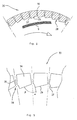
- FIG 6 there is, shown an end view of a cylindrical screen 26 according to a preferred embodiment of the present invention with flow deflecting members 22 arranged on the internal side of the screen 26.
- the screen 26 consists of a plate on which parallel grooves 28 have been milled, so that the inner surface of the screen 26 has a saw-tooth contour with steep flanks 27, which constitute the flow deflecting members, and flattened tooth backs 29.
- In the area of each groove 28 one single screen hole 30 is arranged, as seen in the circumferential direction of the screen 26.
- FIG 7 there is shown an end view of a cylindrical screen 31, according to another embodiment of the invention, which has the same saw-toothed contour as the screen 26 according to figure 6. However, it differs from the screen 26 in that the saw-tooth contour is arranged on the external side of the screen 31.
- the screen 31 is intended for the kind of pressure screening apparatus which separates a suspension flow flowing from outside and into the screen 31. In this case, rotor wings 32 sweeping along the external side of the screen 31 are arranged.
- FIG 8 there is shown a part of a cross-section through the screen 26 according to figure 6.
- the screen 26 may advantageously be produced in the following way.
- a multiplicity of elongated parallel grooves 28 are formed by material reducing machining of the plate, preferably milling.
- Each groove 28 is formed as a V, as seen in a cross-section through the groove 28, with a right angle between the legs of the V, so that the plate has a saw-toothed contour with steep flanks 27 and flattened tooth backs 29.
- the distance between adjacent flanks is less than 6 mm.
- Screen holes 30 are formed in the plate in the area of each groove 28 by means of a laser beam which cuts through the plate from the opposite groove-less side of the plate.
- the laser beam is focused outside the plate adjacent the side of the plate which is provided with the grooves 28, whereby the laser beam converges through the plate and forms screen holes 30 which diverge from the grooves 28 to the groove-less side of the plate.
- the plate is moved relative to the laser beam, so that the screen hole 30 takes the form of a slot extending along its groove 28.
- the plate is bent with grooves 28 and screen holes 30 to a cylindrical shape, so that the grooves 28 are on the internal side of the cylindrical plate and extend obliquely relative to the centre axis of the cylindrical plate. Due to the bending of the plate to the cylindrical shape, the angle between the flank 27 and the tooth back 29 of each groove 28 becomes less than 90°. In addition to this, the inlet opening of each screen hole 30 becomes thinner.
- a simple way of forming the obliquely extending grooves 28 is to start from a rectangular plane plate and form the grooves 28 so that they extend obliquely relative to the side edges of the plate, after which the plate is bent to its cylindrical shape so that two of the opposite side edges of the plate abut each other.
- the plane plate may initially be provided with the grooves 28 and then be cut to rectangular shape, so that the grooves extend obliquely relative to the side edges of the plate.
- the screen holes 30 may also be formed by water cutting. In this case, however, each cutting water jet is ejected towards the side of the plane plate which is provided with the grooves 28.
- Figure 9 shows a part of an end view of a screen 33 according to another embodiment of the invention.
- the screen 33 resembles the screen 26 in that it has the same saw-toothed contour on its internal side.
- the screen 33 differs from the screen 26 in that it is formed by a multiplicity of separate elongated wall elements 34, which are arranged in a circular row. Adjacent wall elements 34 extend in parallel with and at a small distance from each other, so that an elongated gap 35 is formed between them and constitutes a screen hole.
- the wall elements 34 have a cross sectional shape which gives a saw-toothed inner contour of the screen 33 which is identical to the inner contour of the screen 26 according to figure 8.
- FIG 9 there is shown an angle ⁇ between the radius of the screen 33 and a flank 27 of a groove 28, and an angle ⁇ between the radius of the screen 33 and the tooth back 29 of said groove 28.
- the sum of the angles ⁇ and ⁇ is less than 90°.
- This angle sum may, however, be greater than 90°.
- the angle ⁇ may vary between 5-80° and the angle ⁇ may vary between 5-85°.
- the angles ⁇ and ⁇ may also be equivalent. However, it is preferred that the angle ⁇ is somewhat less than 15° and that the angle ⁇ is somewhat less than 75°.
- the angle figures stated are also applicable to the screen 26 according to figure 8.
Landscapes
- Chemical & Material Sciences (AREA)
- Chemical Kinetics & Catalysis (AREA)
- Engineering & Computer Science (AREA)
- Mechanical Engineering (AREA)
- Separation Of Solids By Using Liquids Or Pneumatic Power (AREA)
- Paper (AREA)
- Filtering Materials (AREA)
- Processing Of Solid Wastes (AREA)
- Diaphragms For Electromechanical Transducers (AREA)
- Combined Means For Separation Of Solids (AREA)
- Materials For Medical Uses (AREA)
- Inert Electrodes (AREA)
- Photoreceptors In Electrophotography (AREA)
Claims (17)
- Tamis cylindrique (16, 26, 31, 33) ayant un côté d'admission et un côté de sortie pour le type d'appareil de tamisage sous pression, qui est destiné à la séparation de particules non voulues de suspensions de pâte à papier et qui a un rotor (5) ayant un certain nombre d'aile rotatoires (9) adaptées pour se déplacer le long d'un trajet cylindrique, lequel est coaxial au tamis cylindrique et s'étend assez près du côté d'admission du tamis, lequel tamis comprend une extrémité d'admission axiale (11) au niveau du côté d'admission pour recevoir la suspension à séparer, une extrémité de rejet axiale (13) au niveau du côté d'admission pour éliminer les particules séparées, des éléments de déviation de flux allongés (22, 24, 25, 27), lesquels sont disposés sur le côté d'admission du tamis et distribués autour de la circonférence du tamis, et des trous de tamis (23, 30, 35) disposés entre les éléments de déviation de flux, chaque élément de déviation de flux allongé s'étendant obliquement par rapport à l'axe central du tamis cylindrique et vers l'avant par rapport au sens de rotation desdites ailes rotatoires vu depuis l'extrémité d'admission du tamis vers l'extrémité de rejet du tamis, par lequel durant le fonctionnement, quand le tamis est monté dans ledit appareil de tamisage sous pression, lesdits éléments de déviation de flux dévient le flux de suspension contenant les particules séparées qui sont entraínées par lesdites ailes rotatoires le long dudit trajet cylindrique, de telle sorte que le flux de suspension acquière une composante de mouvement vers l'extrémité de rejet du tamis, caractérisé en ce que la distance entre des éléments de déviation de flux opérationnels adjacents (22, 24, 25, 27) vue dans le sens circonférentiel du tamis est inférieure à 6 mm.
- Tamis selon la revendication 2, caractérisé en ce que chaque élément de déviation de flux allongé (22, 24, 25, 27) forme un angle avec la génératrice (G) du tamis cylindrique qui est compris dans la gamme de 1 à 40°.
- Tamis selon la revendication 2, caractérisé en ce que chaque élément de déviation de flux (22) forme un angle constant (a) avec la génératrice (G) du tamis cylindrique.
- Tamis selon la revendication 2, caractérisé en ce que chaque élément de déviation de flux (24 ; 25) forme un angle (b1 ; c1) avec ladite génératrice (G) relativement près de l'extrémité de rejet (13) du tamis qui est supérieur à l'angle (b2 ; c2) que forme chaque élément de déviation de flux avec ladite génératrice relativement près de l'extrémité d'admission (11) du tamis.
- Tamis selon la revendication 4, caractérisé en ce que chaque élément de déviation de flux (25) forme un angle (c1, c2) avec ladite génératrice (G) qui augmente continuellement quand la génératrice est déplacée de telle sorte que le point d'intersection entre ledit élément et la génératrice se déplace dans un sens vers l'extrémité de rejet (13) du tamis.
- Tamis selon la revendication 4, caractérisé en ce que chaque élément de déviation de flux (24) forme un angle (b1, b2) avec ladite génératrice (G) qui augmente par gradins quand la génératrice est déplacée de telle sorte que le point d'intersection entre ledit élément et la génératrice se déplace dans un sens vers l'extrémité de rejet (13) du tamis.
- Tamis selon l'une quelconque des revendications 1 à 6, caractérisé en ce que le tamis (26) est formé par une plaque plane d'épaisseur uniforme, qui est courbée en une forme cylindrique, en ce qu'une multiplicité de rainures parallèles allongées (28) sont formées dans la plaque du côté d'admission du tamis par un usinage réducteur de matière de la plaque, en ce que les trous de tamis (30) du tamis s'ouvrent dans lesdites rainures, et en ce que les rainures sont confinées par des surfaces de parois allongées (27, 29) constituant lesdits éléments de déviation de flux.
- Tamis selon la revendication 7, caractérisé en ce que les trous de tamis (30) sont orientés en rangées, une seule rangée de trous de tamis s'étendant entre des éléments de déviation de flux adjacents (27, 29).
- Tamis selon l'une quelconque des revendications 1 à 6, caractérisé en ce que le tamis (33) est formé par une multiplicité d'éléments de parois solides allongés séparés (34), lesquels sont disposés en une rangée circulaire, des éléments de parois adjacents s'étendant en parallèle les uns aux autres à et à une petite distance les uns des autres, de telle sorte qu'un espace allongé (35) soit formé entre eux et constitue un desdits trous de tamis, et en ce que sur le côté d'admission du tamis, des éléments de parois adjacents forment des rainures qui sont confinées par des surfaces de parois allongées (27, 29) constituant lesdits éléments de déviation de flux.
- Tamis selon l'une quelconque des revendications précédentes, caractérisé en ce que ledit côté d'admission est formé par le côté interne du tamis.
- Tamis selon l'une quelconque des revendications 1 à 9, caractérisé en ce que ledit côté d'admission est formé par le côté externe du tamis.,
- Procédé de production d'un tamis cylindrique destiné à être utilisé dans un appareil de filtrage sous pression conçu pour séparer des particules non voulues de suspensions de pâte à papier, comprenant les étapes de :caractérisé en ce que lesdits trous de tamis sont formés dans la plaque plane de telle sorte qu'ils s'étendent depuis lesdites rainures et divergent vers le côté opposé de la plaque, en ce que lesdites rainures sont formées de manière à laisser des rebords des deux côtés de chaque rainure, formant des éléments de déviation de flux (22, 24, 25, 27) sur le tamis achevé, la distance entre les éléments de déviation de flux formés étant inférieure à six millimètres dans le sens circonférentiel du tamis, et en ce que le tamis est formé de telle sorte que lesdites rainures s'étendent obliquement par rapport à l'axe central de la plaque cylindrique quand la plaque a été courbée dans sa forme cylindrique.formation d'une multiplicité de rainures parallèles allongées (28) sur un côté d'une plaque plane d'épaisseur uniforme par un usinage réducteur de matière de la plaque,formation de trous de filtrage (30) dans la plaque plane dans la zone de chaque rainure par découpe de la plaque, etcourbure de la plaque en une forme cylindrique, de telle sorte que les rainures se trouvent sur le côté interne de la plaque cylindrique,
- Procédé selon la revendication 12, caractérisé en ce que la plaque plane est rectangulaire, en ce que les rainures organisées (28) sont formées de telle sorte qu'elles s'étendent obliquement par rapport aux arêtes latérales de la plaque, et en ce que la plaque est courbée en sa forme cylindrique de façon à ce que deux des arêtes latérales opposées de la plaque se jouxtent.
- Procédé selon la revendication 12, caractérisé en ce qu'avant que la plaque plane à rainures formées (28) ne soit courbée en une forme cylindrique, elle est coupée en une forme rectangulaire, de telle sorte que les rainures s'étendent obliquement par rapport aux arêtes latérales de la plaque, et en ce que la plaque rectangulaire est courbée en une forme cylindrique de façon à ce que deux des arêtes latérales opposées de la plaque se jouxtent.
- Procédé selon l'une quelconque des revendications 12 à 14, caractérisé en ce que chaque trou de tamis (30) est formé par découpe au laser.
- Procédé selon la revendication 15, caractérisé en ce que chaque trou de tamis (30) est formé au moyen d'un faisceau laser qui coupe à travers la plaque plane à partir dudit côté opposé de la plaque, le faisceau laser ayant une coupe transversale axiale qui converge à travers la plaque dans le sens depuis ledit côté opposé vers ledit un côté de la plaque.
- Procédé selon l'une quelconque des revendications 12 à 14, caractérisé en ce que chaque trou de tamis (30) est formé par découpe à l'eau.
Applications Claiming Priority (3)
| Application Number | Priority Date | Filing Date | Title |
|---|---|---|---|
| SE9604801 | 1996-12-27 | ||
| SE9604801A SE517110C2 (sv) | 1996-12-27 | 1996-12-27 | Cylindrisk sil och sätt att framställa denna |
| PCT/SE1997/002202 WO1998029599A1 (fr) | 1996-12-27 | 1997-12-22 | Classeur cylindrique et procede de production correspondant |
Publications (2)
| Publication Number | Publication Date |
|---|---|
| EP0912794A1 EP0912794A1 (fr) | 1999-05-06 |
| EP0912794B1 true EP0912794B1 (fr) | 2002-11-27 |
Family
ID=20405153
Family Applications (1)
| Application Number | Title | Priority Date | Filing Date |
|---|---|---|---|
| EP97952160A Revoked EP0912794B1 (fr) | 1996-12-27 | 1997-12-22 | Classeur cylindrique et procede de production correspondant |
Country Status (11)
| Country | Link |
|---|---|
| EP (1) | EP0912794B1 (fr) |
| JP (1) | JP2000507319A (fr) |
| KR (1) | KR19990087286A (fr) |
| AT (1) | ATE228594T1 (fr) |
| AU (1) | AU5581998A (fr) |
| BR (1) | BR9707865A (fr) |
| CA (1) | CA2241945A1 (fr) |
| DE (1) | DE69717452D1 (fr) |
| NO (1) | NO983912L (fr) |
| SE (1) | SE517110C2 (fr) |
| WO (1) | WO1998029599A1 (fr) |
Families Citing this family (2)
| Publication number | Priority date | Publication date | Assignee | Title |
|---|---|---|---|---|
| SE510539C2 (sv) | 1997-09-12 | 1999-05-31 | Gl & V Celleco Ab | Sätt vid framställning av en silplåt samt silelement omfattande en eller flera silplåtar |
| WO2026083373A1 (fr) * | 2024-10-14 | 2026-04-23 | PT Green Eco Nickel | Système de lavage à double vis pour minerai de nickel latéritique |
Family Cites Families (3)
| Publication number | Priority date | Publication date | Assignee | Title |
|---|---|---|---|---|
| CA1180686A (fr) * | 1980-08-25 | 1985-01-08 | Black Clawson Company (The) | Filtre de pate a papier, avec tamis tubulaire sous pression |
| SE9102550L (sv) * | 1991-09-05 | 1993-03-06 | Sunds Defibrator Ind Ab | Saett foer framstaellning av en siltrumma |
| FI89521C (fi) * | 1991-10-04 | 1993-10-11 | Cae Investments Bv | Foerfarande foer framstaellning av en silprodukt och genom foerfarandet framstaelld silprodukt |
-
1996
- 1996-12-27 SE SE9604801A patent/SE517110C2/sv not_active IP Right Cessation
-
1997
- 1997-12-22 KR KR1019980706688A patent/KR19990087286A/ko not_active Ceased
- 1997-12-22 WO PCT/SE1997/002202 patent/WO1998029599A1/fr not_active Ceased
- 1997-12-22 AU AU55819/98A patent/AU5581998A/en not_active Abandoned
- 1997-12-22 DE DE69717452T patent/DE69717452D1/de not_active Expired - Lifetime
- 1997-12-22 CA CA002241945A patent/CA2241945A1/fr not_active Abandoned
- 1997-12-22 EP EP97952160A patent/EP0912794B1/fr not_active Revoked
- 1997-12-22 BR BR9707865A patent/BR9707865A/pt not_active Application Discontinuation
- 1997-12-22 JP JP10529921A patent/JP2000507319A/ja active Pending
- 1997-12-22 AT AT97952160T patent/ATE228594T1/de not_active IP Right Cessation
-
1998
- 1998-08-26 NO NO983912A patent/NO983912L/no not_active Application Discontinuation
Also Published As
| Publication number | Publication date |
|---|---|
| BR9707865A (pt) | 1999-07-27 |
| DE69717452D1 (de) | 2003-01-09 |
| SE9604801L (sv) | 1998-06-28 |
| SE9604801D0 (sv) | 1996-12-27 |
| NO983912D0 (no) | 1998-08-26 |
| WO1998029599A1 (fr) | 1998-07-09 |
| JP2000507319A (ja) | 2000-06-13 |
| ATE228594T1 (de) | 2002-12-15 |
| KR19990087286A (ko) | 1999-12-27 |
| AU5581998A (en) | 1998-07-31 |
| SE517110C2 (sv) | 2002-04-16 |
| EP0912794A1 (fr) | 1999-05-06 |
| NO983912L (no) | 1998-08-27 |
| CA2241945A1 (fr) | 1998-07-09 |
Similar Documents
| Publication | Publication Date | Title |
|---|---|---|
| EP0637348B1 (fr) | Appareil de traitement de suspensions fibreuses | |
| US5147543A (en) | Rotating element for a screening apparatus with a contour surface produced by a plurality of protrusions in the direction of the axial length of the cylindrical rotor | |
| RU2401890C2 (ru) | Плита статора рафинера, имеющая наружный ряд зубьев, наклоненных для отклонения волокнистого материала, и способ отклонения волокнистого материала во время рафинирования | |
| CN1213418A (zh) | 纸浆筛桶 | |
| EP0205623B1 (fr) | Ecran a fentes a pression | |
| US4744894A (en) | Fibrous stock screening apparatus | |
| US5607589A (en) | Multiple contour screening | |
| KR19990072357A (ko) | 폐지펄프를스크린하기위한방법및장치 | |
| EP0912794B1 (fr) | Classeur cylindrique et procede de production correspondant | |
| US5172813A (en) | Method and an apparatus for treating fiber suspension | |
| EP1124004B1 (fr) | Appareil pour l'épuration d'une pâte à papier | |
| US6425486B1 (en) | Cylindrical screen and a method of manufacturing it | |
| EP1184509B1 (fr) | Classeur pour suspension fibreuse | |
| JPS62503109A (ja) | 輪郭表面を有するスクリ−ニング装置に使用される回転要素 | |
| EP0294832A2 (fr) | Appareil pour l'épuration de pâte | |
| JPH0536553B2 (fr) | ||
| US7987991B2 (en) | Pulper with screen plate having maximum defibering edges | |
| DE10233364C1 (de) | Drucksortierer zum Sieben einer Faserstoffsuspension | |
| US6479789B1 (en) | Manufacture of screen plate with screen slots obtained by laser beam cutting | |
| JPH0536554B2 (fr) | ||
| EP1612326B1 (fr) | Tamis sous pression pour tamiser une suspension de fibres | |
| US20120318721A1 (en) | Grooved screen used in a tramp material separator | |
| SU1293261A1 (ru) | Сортирующий гидроразбавитель | |
| FI73892C (fi) | Sjaelvrenande filter foer viskoesa suspensioner. | |
| JPS63242384A (ja) | スクリ−ンプレ−ト |
Legal Events
| Date | Code | Title | Description |
|---|---|---|---|
| PUAI | Public reference made under article 153(3) epc to a published international application that has entered the european phase |
Free format text: ORIGINAL CODE: 0009012 |
|
| 17P | Request for examination filed |
Effective date: 19980714 |
|
| AK | Designated contracting states |
Kind code of ref document: A1 Designated state(s): AT BE DE ES FI FR GB GR IT PT SE |
|
| RAP1 | Party data changed (applicant data changed or rights of an application transferred) |
Owner name: GL&V/CELLECO AB |
|
| 17Q | First examination report despatched |
Effective date: 20010514 |
|
| GRAG | Despatch of communication of intention to grant |
Free format text: ORIGINAL CODE: EPIDOS AGRA |
|
| GRAG | Despatch of communication of intention to grant |
Free format text: ORIGINAL CODE: EPIDOS AGRA |
|
| GRAH | Despatch of communication of intention to grant a patent |
Free format text: ORIGINAL CODE: EPIDOS IGRA |
|
| RAP1 | Party data changed (applicant data changed or rights of an application transferred) |
Owner name: GL&V SWEDEN AB |
|
| GRAH | Despatch of communication of intention to grant a patent |
Free format text: ORIGINAL CODE: EPIDOS IGRA |
|
| GRAA | (expected) grant |
Free format text: ORIGINAL CODE: 0009210 |
|
| AK | Designated contracting states |
Kind code of ref document: B1 Designated state(s): AT BE DE ES FI FR GB GR IT PT SE |
|
| PG25 | Lapsed in a contracting state [announced via postgrant information from national office to epo] |
Ref country code: IT Free format text: LAPSE BECAUSE OF FAILURE TO SUBMIT A TRANSLATION OF THE DESCRIPTION OR TO PAY THE FEE WITHIN THE PRE;WARNING: LAPSES OF ITALIAN PATENTS WITH EFFECTIVE DATE BEFORE 2007 MAY HAVE OCCURRED AT ANY TIME BEFORE 2007. THE CORRECT EFFECTIVE DATE MAY BE DIFFERENT FROM THE ONE RECORDED.SCRIBED TIME-LIMIT Effective date: 20021127 Ref country code: GR Free format text: LAPSE BECAUSE OF FAILURE TO SUBMIT A TRANSLATION OF THE DESCRIPTION OR TO PAY THE FEE WITHIN THE PRESCRIBED TIME-LIMIT Effective date: 20021127 Ref country code: FR Free format text: LAPSE BECAUSE OF FAILURE TO SUBMIT A TRANSLATION OF THE DESCRIPTION OR TO PAY THE FEE WITHIN THE PRESCRIBED TIME-LIMIT Effective date: 20021127 Ref country code: FI Free format text: LAPSE BECAUSE OF FAILURE TO SUBMIT A TRANSLATION OF THE DESCRIPTION OR TO PAY THE FEE WITHIN THE PRESCRIBED TIME-LIMIT Effective date: 20021127 Ref country code: BE Free format text: LAPSE BECAUSE OF FAILURE TO SUBMIT A TRANSLATION OF THE DESCRIPTION OR TO PAY THE FEE WITHIN THE PRESCRIBED TIME-LIMIT Effective date: 20021127 Ref country code: AT Free format text: LAPSE BECAUSE OF FAILURE TO SUBMIT A TRANSLATION OF THE DESCRIPTION OR TO PAY THE FEE WITHIN THE PRESCRIBED TIME-LIMIT Effective date: 20021127 |
|
| REF | Corresponds to: |
Ref document number: 228594 Country of ref document: AT Date of ref document: 20021215 Kind code of ref document: T |
|
| REG | Reference to a national code |
Ref country code: GB Ref legal event code: FG4D |
|
| REF | Corresponds to: |
Ref document number: 69717452 Country of ref document: DE Date of ref document: 20030109 |
|
| PG25 | Lapsed in a contracting state [announced via postgrant information from national office to epo] |
Ref country code: SE Free format text: LAPSE BECAUSE OF FAILURE TO SUBMIT A TRANSLATION OF THE DESCRIPTION OR TO PAY THE FEE WITHIN THE PRESCRIBED TIME-LIMIT Effective date: 20030227 Ref country code: PT Free format text: LAPSE BECAUSE OF FAILURE TO SUBMIT A TRANSLATION OF THE DESCRIPTION OR TO PAY THE FEE WITHIN THE PRESCRIBED TIME-LIMIT Effective date: 20030227 Ref country code: GB Free format text: LAPSE BECAUSE OF NON-PAYMENT OF DUE FEES Effective date: 20030227 |
|
| PG25 | Lapsed in a contracting state [announced via postgrant information from national office to epo] |
Ref country code: DE Free format text: LAPSE BECAUSE OF FAILURE TO SUBMIT A TRANSLATION OF THE DESCRIPTION OR TO PAY THE FEE WITHIN THE PRESCRIBED TIME-LIMIT Effective date: 20030228 |
|
| PG25 | Lapsed in a contracting state [announced via postgrant information from national office to epo] |
Ref country code: ES Free format text: LAPSE BECAUSE OF FAILURE TO SUBMIT A TRANSLATION OF THE DESCRIPTION OR TO PAY THE FEE WITHIN THE PRESCRIBED TIME-LIMIT Effective date: 20030529 |
|
| PLBQ | Unpublished change to opponent data |
Free format text: ORIGINAL CODE: EPIDOS OPPO |
|
| EN | Fr: translation not filed | ||
| PLBI | Opposition filed |
Free format text: ORIGINAL CODE: 0009260 |
|
| PLAX | Notice of opposition and request to file observation + time limit sent |
Free format text: ORIGINAL CODE: EPIDOSNOBS2 |
|
| GBPC | Gb: european patent ceased through non-payment of renewal fee | ||
| 26 | Opposition filed |
Opponent name: METSO PAPER SUNDSVALL ABMESTO PAPER SUNDSVALL AB Effective date: 20030826 |
|
| RDAF | Communication despatched that patent is revoked |
Free format text: ORIGINAL CODE: EPIDOSNREV1 |
|
| RDAG | Patent revoked |
Free format text: ORIGINAL CODE: 0009271 |
|
| STAA | Information on the status of an ep patent application or granted ep patent |
Free format text: STATUS: PATENT REVOKED |
|
| 27W | Patent revoked |
Effective date: 20040130 |
|
| PLAB | Opposition data, opponent's data or that of the opponent's representative modified |
Free format text: ORIGINAL CODE: 0009299OPPO |