EP0912848B1 - Gleitringdichtungsvorrichtung für rotierende fluidgeräte - Google Patents
Gleitringdichtungsvorrichtung für rotierende fluidgeräte Download PDFInfo
- Publication number
- EP0912848B1 EP0912848B1 EP97924823A EP97924823A EP0912848B1 EP 0912848 B1 EP0912848 B1 EP 0912848B1 EP 97924823 A EP97924823 A EP 97924823A EP 97924823 A EP97924823 A EP 97924823A EP 0912848 B1 EP0912848 B1 EP 0912848B1
- Authority
- EP
- European Patent Office
- Prior art keywords
- shaft
- seal
- arrangement
- disc member
- protector
- Prior art date
- Legal status (The legal status is an assumption and is not a legal conclusion. Google has not performed a legal analysis and makes no representation as to the accuracy of the status listed.)
- Expired - Lifetime
Links
- 239000012530 fluid Substances 0.000 title claims description 35
- 230000001012 protector Effects 0.000 claims description 44
- 230000000694 effects Effects 0.000 claims description 9
- 230000001939 inductive effect Effects 0.000 claims description 7
- 238000007789 sealing Methods 0.000 claims description 4
- 238000007373 indentation Methods 0.000 claims description 3
- 239000003082 abrasive agent Substances 0.000 description 20
- 239000000356 contaminant Substances 0.000 description 7
- 210000004907 gland Anatomy 0.000 description 7
- 238000013461 design Methods 0.000 description 5
- 239000000463 material Substances 0.000 description 5
- 230000003134 recirculating effect Effects 0.000 description 5
- 230000003628 erosive effect Effects 0.000 description 4
- 238000005086 pumping Methods 0.000 description 4
- 230000004323 axial length Effects 0.000 description 3
- 238000001816 cooling Methods 0.000 description 3
- 230000005484 gravity Effects 0.000 description 3
- 230000002093 peripheral effect Effects 0.000 description 3
- 238000009825 accumulation Methods 0.000 description 2
- 230000009471 action Effects 0.000 description 2
- 230000000712 assembly Effects 0.000 description 2
- 238000000429 assembly Methods 0.000 description 2
- 230000006835 compression Effects 0.000 description 2
- 238000007906 compression Methods 0.000 description 2
- 239000000411 inducer Substances 0.000 description 2
- 238000009434 installation Methods 0.000 description 2
- 238000003754 machining Methods 0.000 description 2
- 230000007246 mechanism Effects 0.000 description 2
- 239000002184 metal Substances 0.000 description 2
- 238000012986 modification Methods 0.000 description 2
- 230000004048 modification Effects 0.000 description 2
- 238000000465 moulding Methods 0.000 description 2
- 238000013021 overheating Methods 0.000 description 2
- 239000004033 plastic Substances 0.000 description 2
- 229920003023 plastic Polymers 0.000 description 2
- 230000009467 reduction Effects 0.000 description 2
- 230000009977 dual effect Effects 0.000 description 1
- 230000017525 heat dissipation Effects 0.000 description 1
- 230000020169 heat generation Effects 0.000 description 1
- 230000001788 irregular Effects 0.000 description 1
- 238000004519 manufacturing process Methods 0.000 description 1
- 239000003607 modifier Substances 0.000 description 1
- 239000002245 particle Substances 0.000 description 1
- 238000004080 punching Methods 0.000 description 1
- 239000007787 solid Substances 0.000 description 1
- 238000010561 standard procedure Methods 0.000 description 1
- 238000012546 transfer Methods 0.000 description 1
- 230000007704 transition Effects 0.000 description 1
- 238000003466 welding Methods 0.000 description 1
Images


Classifications
-
- F—MECHANICAL ENGINEERING; LIGHTING; HEATING; WEAPONS; BLASTING
- F04—POSITIVE - DISPLACEMENT MACHINES FOR LIQUIDS; PUMPS FOR LIQUIDS OR ELASTIC FLUIDS
- F04D—NON-POSITIVE-DISPLACEMENT PUMPS
- F04D29/00—Details, component parts, or accessories
- F04D29/08—Sealings
- F04D29/10—Shaft sealings
- F04D29/106—Shaft sealings especially adapted for liquid pumps
-
- F—MECHANICAL ENGINEERING; LIGHTING; HEATING; WEAPONS; BLASTING
- F16—ENGINEERING ELEMENTS AND UNITS; GENERAL MEASURES FOR PRODUCING AND MAINTAINING EFFECTIVE FUNCTIONING OF MACHINES OR INSTALLATIONS; THERMAL INSULATION IN GENERAL
- F16J—PISTONS; CYLINDERS; SEALINGS
- F16J15/00—Sealings
- F16J15/16—Sealings between relatively-moving surfaces
- F16J15/34—Sealings between relatively-moving surfaces with slip-ring pressed against a more or less radial face on one member
- F16J15/3404—Sealings between relatively-moving surfaces with slip-ring pressed against a more or less radial face on one member and characterised by parts or details relating to lubrication, cooling or venting of the seal
-
- F—MECHANICAL ENGINEERING; LIGHTING; HEATING; WEAPONS; BLASTING
- F05—INDEXING SCHEMES RELATING TO ENGINES OR PUMPS IN VARIOUS SUBCLASSES OF CLASSES F01-F04
- F05B—INDEXING SCHEME RELATING TO WIND, SPRING, WEIGHT, INERTIA OR LIKE MOTORS, TO MACHINES OR ENGINES FOR LIQUIDS COVERED BY SUBCLASSES F03B, F03D AND F03G
- F05B2240/00—Components
- F05B2240/70—Slinger plates or washers
Definitions
- This invention relates to a mechanical seal arrangement comprising a flow controller or seal protector which is useful in protecting mechanical seals in rotating equipment from abrasives in the pumpage, air in the pumping system, and overheating due to frictional heat.
- a flow controller or seal protector which is useful in protecting mechanical seals in rotating equipment from abrasives in the pumpage, air in the pumping system, and overheating due to frictional heat.
- dual flow patterns in the region of the mechanical seal are developed: one drives abrasives away from the seal faces, while the other drives air away from the seal faces and removes frictional heat.
- Rotary fluid equipment such as centrifugal pumps, usually includes a rotary operative member (such as an impeller) which is driven by a prime mover (such as an electrical motor) by way of a shaft.
- a rotary operative member such as an impeller
- prime mover such as an electrical motor
- This rotating element is contained within a stationary housing.
- Most pumps incorporate a mechanical seal at the point where the rotating shaft passes through the stationary housing, to prevent fluid leakage.
- particulate contaminant material carried into the seal area by the pumpage can damage the seal unless some type of protector is arranged to deflect them away from the area.
- EP-A-0 388 384 teaches a mechanical seal for a seal arrangement used in a submersible rotary machine.
- a spring acts on a cup surrounding the shaft to force a rotary seal against a stationary seal. This structure is not effective in preventing particulate contaminants from damaging the stationary seal.
- Abrasives are centrifuged to the bore, where the flow forces them in the direction of the seal faces, but when they reach the area of the seal gland, they are prohibited from turning radially inward with the fluid flow, by centrifugal force. This results in the abrasives rotating in the same location until they wear out, or cause erosion on, the seal cavity and seal components.
- the current invention establishes two flow patterns in the seal cavity, which individually drive abrasives and air away from the seal faces, while eliminating the erosion problems associated with taper bore seal cavities.
- the invention requires no pump modifications for installation, or operation.
- the present invention provides a mechanical seal arrangement comprising a seal protector which is secured to the shaft and is therefore rotary in operation, as opposed to being stationary as in the prior art.
- This controller is intended to be applicable to a wide range of centrifugal equipment and installed without the need for machining or modification.
- the controller makes use of the fact that within the pump every rotating radial surface exposed to the fluid induces a flow outward from the center of the surface. It also makes use of two other commonly known concepts: abrasives of higher specific gravity than the fluid will centrifuge outwardly; and contaminants or gas lighter than the fluid will centrifuge towards the center. The behaviour of the abrasives or air when they centrifuge to the bore or shaft respectively depends upon the direction of any axial component of the fluid flow at that surface.
- the present invention provides a radial annular ring, attached at its outer periphery to, or formed integrally with, an axial cylindrical (or tubular) component that extends over the body of the mechanical seal.
- an axial cylindrical (or tubular) component that extends over the body of the mechanical seal.
- a flared portion forming a frustoconical section.
- a series of external protrusions, or bumps that serve as flow inducers.
- the combination is secured to the rotating shaft by a set screwed locking ring, by being clamped by the compression of the seal against the back of the impeller, or by direct attachment to the mechanical seal or impeller, to form a shroud or cover over the mechanical seal from its back, towards the seal face.
- Sufficient radial space is allowed (at least 3.2 mm, or 1 ⁇ 8 of an inch, or more) between the inner cylindrical surface of the device and the outer cylindrical surface of the seal to permit fluid circulation.
- the rotational operation of the invention creates two flow patterns, an outer pattern which drives abrasives from the seal area, and an inner pattern which delivers abrasives into the outer flow, and drives air away from the seal faces, to prevent dry running and overheating.
- the shaft rotates the seal protector along with the mechanical seal.
- the rotation of the flow inducers on the outside of the axial tubular (or cylindrical) and frustoconical surfaces, drives a flow along the bore in a direction towards the impeller. This then draws a return flow back along the outer surface of the axial cylindrical section, to complete the outer flow loop. Since abrasives centrifuge to the bore, the flow pattern continuously drives them towards the impeller, where centrifugal forces move them radially outwardly along the back of the impeller and into the pumpage.
- the frictional effects of the radial surface of the annular ring drives a low velocity flow in a radial, or outward, direction from the shaft.
- the cylindrical (tubular) section guides the flow axially in the direction of the seal face. Since abrasives are normally higher in specific gravity than the fluid they are centrifuged to the inner surface of the tubular section, and are driven along with the axial flow. When the abrasives reach the gap at the open end of the controller, they are centrifuged through the opening and out of the shrouded area.
- the fluid will flow smoothly across the gap and then radially inwardly, toward the seal face, and then axially along the outer surface of the mechanical seal back to the inner diameter of the radial annular ring, completing the inner flow loop. Since air centrifuges radially inwardly, this direction of flow will force any air accumulation away from the seal face, toward the back of the seal. After a few revolutions the abrasives are expelled from within the shrouded volume, air is pushed to the back of the seal, and the mechanical seal operates in a clean environment.
- This version would be used in the type of pumps in which the mechanical seal is directly compressed against the back of the impeller, and the stationary seat is pressed into a recess in the pump back plate.
- These types of mechanical seals are normally short in axial length (about 12.7 to 19 mm or 1 ⁇ 2 to 3 ⁇ 4 inch) and are sensitive to the presence of abrasives.
- a second version of the invention utilizes small vanes (or radial bumps) on the inside surface of the radial annular ring to provide a pumping action to increase the velocity of the inner circulation loop. This will be necessary for seals of longer axial length (more sophisticated seals are typically 25.4 to 51 mm or 1 to 2 inches in length) since many such designs have irregular surface configurations which can introduce unwanted vortices that must be overcome with the additional fluid drive offered by the vanes.
- a third version incorporates a series of vent openings in the outer circumference of the radial annular ring instead of the impeller vanes. These vents are configured to open towards the mechanical seal and away from the direction of rotation so that the recirculating flow passing over the vent creates a suction effect which draws additional fluid into the shrouded volume. This additional flow combines with the normal circulation flow.
- the vents also behave as small impeller vanes to drive the total flow axially along the inside surface of the tubular member toward the gap near the seal gland, in a manner similar to that driven by the vanes of the previous version. The additional flow introduced by the operation of the vents then exits through the gap at the end of the tubular member.
- the exiting flow enhances the rate of particulate removal from the shrouded volume and mixes with the recirculating flow to achieve enhanced heat removal.
- the gap must be no shorter than 3.2 mm (1 ⁇ 8 inch) and no longer than 12.7 mm (1 ⁇ 2 inch) axially to ensure that undesirable vortices are not formed. This version would be used in applications where the seal requires additional cooling as is typical in many refinery and heat transfer services, in crystallizing fluids where hard seal faces are necessary, or in large diameter seals under high pressure, since greater heat generation occurs in these applications.
- An enhancement to this version is to curve the radial annular ring towards the seal, just inside the radius of the vents. When this configuration is pressed against the impeller, or attached to a locking ring, an annular orifice is created to protect against plugging of the vent openings by large contaminants. It should be noted that with this design, plugging of the vents does not inhibit operation, but reduces the fluid exchanged to that of the version with the flow inducing vanes.
- An additional enhancement provides for holes that pass axially through the locking ring, and connect between the two radial surfaces.
- the holes can be drilled, cast, or formed, and allow greater volumes of air to be pushed by the flow patterns, through and away from the seal faces in applications involving aerated fluids, or where product tanks are pumped dry.
- Any of the versions can be mounted to the shaft using a locking ring with set screws, by direct attachment to the back of a mechanical seal, by compression between any two components, or by direct attachment to the impeller or other rotating component. Attachment can be accomplished by bolting, welding, or any other standard method.
- the present invention may be considered as providing a mechanical seal arrangement for use with rotary fluid equipment comprising: a seal cavity having an axial open entrance end and defined by a portion of a rotary shaft having an axis, a shaft housing surrounding at least a portion of the shaft, mechanical seal means engaging the shaft, the seal means including a first portion extending axially over at least a part of the portion of the rotary shaft and a second portion performing the sealing with respect to the housing and closing one axial end of the cavity; and a seal cavity protector comprising: a radially extending disc member having circular inner and outer peripheries respectively; means for connecting the disc member adjacent the inner periphery thereof to the shaft at the entrance end for rotation with the shaft; a cylindrical member extending axially from the outer periphery of the disc member into the cavity and being located radially between the housing and the first portion of the seal means to enclose in close radial proximity at least partly the first portion of the seal means, the cylindrical member having a radially extending disc member having
- the invention may also be considered as providing a mechanical seal arrangement for use with rotary fluid equipment comprising: a seal cavity having an axial open entrance end and defined by a portion of a rotary shaft having an axis, a tapered shaft housing surrounding at least a portion of the shaft, mechanical seal means engaging the shaft, the seal means including a first portion extending axially over at least a part of the portion of the rotary shaft and a second portion performing the sealing with respect to the housing and closing one axial end of the cavity; and a seal cavity protector comprising: a radially extending disc member having circular inner-and outer peripheries respectively; an annular flange extending from the inner periphery of the disc member and of a diameter to effect a tight fit on the shaft; an annular locking ring receivable on the flange; set screw means receivable in the locking ring to clamp the flange to the shaft at the cavity entrance end so that the protector can rotate with the shaft; a cylindrical member integrally formed with and extending axial
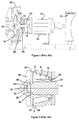
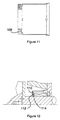
- Figure 1 shows, in partial cross section, an elevational view of a typical rotary fluid equipment in which this invention may be used.
- Figure 2 shows in cross section an enlarged view of a typical seal arrangement in this type of equipment, showing fluid flow patterns around the seal area.
- Figure 3 shows an enlarged view with a seal protector device of the invention installed (compressed against the impeller) and flow patterns associated therewith.
- Figure 4 is an end view of a seal protector in accordance with the present invention.
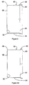
- Figure 5 is a cross section of the seal protector taken on the line 5-5 of Figure 4.
- Figure 5A shows a variant of the embodiment of Figure 5.
- Figure 6 is a cross sectional view similar to Figure 4 showing a variant of the invention, using a set screwed lock ring for securing the controller to the shaft.
- Figure 6A shows a variant of the embodiment of Figure 6.
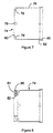
- Figure 7 is a cross sectional view showing a further enhancement to the first variant of the invention.
- Figure 8 is a cross sectional view similar to Figure 6 showing a further enhancement to the second variant of the invention.
- Figure 9 is a cross sectional view similar to Figure 7 showing an enhancement to the first variant of the invention.
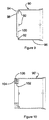
- Figure 10 is a cross sectional view similar to Figure 6 showing a further enhancement to the second variant of the invention.
- Figure 11 is a cross sectional view similar to Figure 10 showing a third enhancement to the second variant of the invention.
- Figure 12 is a cross sectional view similar to Figure 11 showing the current invention mounted directly onto the mechanical seal.
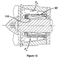
- Figure 13 is a cross sectional view similar to Figure 11 showing the flow patterns in and around the current invention, as installed and operating in a tapered seal cavity.
- FIG. 1 illustrates a typical environment for the device of the present invention.
- the rotary equipment comprises a centrifugal pump 10 which is operated by an electrical motor 12.
- the motor drives a rotary shaft 14 connected within a tapered bearing housing 16.
- the shaft is connected to a centrifugal impeller 18 which, as it rotates, draws fluid in through inlet 20 and pumps the fluid out through radial outlet 22.
- the shaft 14 is typically supported by bearings within the bearing housing 16.
- a seal cavity 28 is defined in general by the shaft 14, the housing 16, the seals 26, and the gland 24.
- FIG. 2 illustrates a somewhat enlarged view of the area where the shaft 14 connects to the impeller 18. It is seen therein that the shaft 14 has a shoulder 30 with a smaller diameter portion 32 extending therefrom. A threaded portion 34 projects from the portion 32. The impeller 18, with vanes 36, fits over the portion 32 and abuts the shoulder 30. A washer 38 and nut 40 are drawn tight against the impeller 18 to clamp it to the shaft 14; and a nose piece 42 fits over the nut, washer and exposed end of the threaded portion 34. With the impeller in place there is a thin gap g between the inner face 44 of the impeller and the outer face 46 of the housing.
- Figure 2 also illustrates typical flow patterns within the seal cavity 28.
- Rotation of the impeller 18 will create a radially outward flow along the rear face thereof, designated by the arrow A.
- a flow designated by the arrow B is set up within the seal cavity, that flow extending along the rear face of the impeller, turning inwardly along the outer surface of the cavity bore to the innermost end of the cavity, where it again turns and is directed generally axially along the seal 26 towards the impeller 18.
- Contaminants such as abrasive particles are carried by the flow B and tend to accumulate at the innermost end of the cavity, where they can damage the seal, the gland and/or the cavity bore.
- FIGS 3 to 6 illustrate the basic form of the seal protector of the present invention.
- the protector 50 includes a generally radial annular ring member 52 affixed to, or formed integrally with, a cylindrical member 54 which extends in one direction from the outer peripheral edge 56 of the ring member 52.
- the inner peripheral edge 58 of the ring member has a diameter that is essentially the same as that of the shaft 14 over which it will be positioned.
- the cylindrical member 54 has a frustoconical flange portion 60 which flares radially outwardly.
- a plurality of circumferentially spaced bumps or protrusions 62 is provided adjacent the free end 64 of the protector, which protrusions extend generally radially outwardly. As shown in Figures 5 and 6 these protrusions, or flow inducing means, are positioned at the transition of the cylindrical member into the flared flange portion thereof.
- the protrusions could easily be positioned solely on the cylindrical member or solely on the flared flange portion itself, the latter configuration being seen in Figures 5A and 6A.
- a first pattern F 1 is set up by the flow inducing protrusions 62.
- the protrusions drive a flow along the bore 16 in a direction towards the impeller, which draws a return flow back along the outer surface of the cylindrical member 54 to complete the flow loop. Since abrasives will centrifuge to the bore, the flow pattern continuously drives them towards the impeller, where centrifugal forces will cast them radially outwardly along the back of the impeller and into the pumpage.
- a second flow pattern F 2 is set up within the protector, the frictional effects of the ring member 52 driving a low velocity flow in a radially outward direction from the shaft,
- the cylindrical member 54 guides the flow axially towards the seal face 66. Since abrasives are normally higher in specific gravity than the fluid they are centrifuged to the inner surface of the cylindrical member 54 and are driven along with the axial flow. When the abrasives reach the gap g at the end of the protector they are centrifuged through the gap and out of the shrouded volume encompassed by the protector 50.
- the fluid, with abrasives being removed therefrom, will flow smoothly across the gap and then radially inwardly, along the seal face 66, and then axially along the outer surface of the seal 26 back to the inner diameter of the annular ring member 52, thereby completing the inner flow loop F 2 . Since air centrifuges radially inwardly, this direction of flow will force any air accumulation away from the seal face, toward the back of the seal. After a few revolutions, the abrasives are expelled from within the shrouded volume, air is pushed to the back of the seal and the mechanical seal operates in a clean environment.
- Figure 6 illustrates a different mechanism for securing the seal protector to the shaft 14.
- the protector 50' has a flange portion 68 which extends axially from the inner edge 58 of the annular ring member 52 in a direction opposite the cylindrical member 54.
- the diameter of the flange portion 68 is such that it has a tight fit on the shaft 14.
- an annular locking ring 70 fits over the flange portion and a plurality of circumferentially spaced set screws 72 are threaded radially inwardly to clamp the flange portion 68 against the shaft so that the protector 50' will rotate with the shaft.
- Figure 7 shows another embodiment 74 of the present invention which might be used with seals of axial length longer than those with which the first embodiment might be used. While the protector of Figures 3 to 6 might be used with seals of about 12.7 to 19 mm (1 ⁇ 2 to 3 ⁇ 4 inch) in length it will be seen that the cylindrical member 76 of this embodiment is longer such that the protector could be used with seals of 25.4 to 51 mm (1 to 2 inches) in length. Furthermore, this version of the present invention utilizes a plurality of vane members 78 which are provided internally of the protector at the junction of the cylindrical member 76 and the annular ring member 80.
- the vane members may be additional pieces attached to the inner walls of the ring and cylindrical members or they may be formed as indentations or grooves formed inwardly from the corner defined at the junction of the ring and cylindrical members.
- the vane members 78 provide a pumping action to the flow within the protector in the vicinity of the annular ring member 80, a necessity with the longer seal configurations with which it will be used. Such configurations may have surface irregularities on the seals which introduce unwanted vortices into the flow.
- the additional fluid drive provided by the vane members helps to overcome such vortices.
- Figure 8 shows a version 74' of the protector of Figure 7 which has a flange portion 82 extending from the inner edge of the annular ring member, along with an annular locking ring 84 and a plurality of set screws 86 which will be used to clamp the flange portion to the shaft 14.
- FIG 9 shows another embodiment 90 which incorporates a series of circumferentially spaced vent openings 92 along the outer periphery of the annular ring member 94.
- These vent openings replace the vane members of the previous embodiment and are configured to open inwardly towards the seal means, and away from the direction of rotation.
- the vent openings are formed in, as by molding or punching, the material of the protector. The recirculating flow passing over the vent openings creates a suction effect which draws additional fluid into the interior of the protector, which additional flow combines with the normal flow within the shrouded volume.
- vent openings are formed to open away from the direction of rotation, they can also perform a function similar to that of the vane members of the previous embodiment, helping to drive the total flow axially along the inside surface of the cylindrical member 96 toward the gap near the seal gland.
- the extra flow exiting through the gap at the end of the cylindrical member enhances the rate of particulate or abrasive removal and mixes with the recirculating flow outside the protector to enhance heat dissipation.
- the gap between the end of the cylindrical member and the seal gland should be in the range of 3.2 to 12.7 mm (1 ⁇ 8 to 1 ⁇ 2 inch) to ensure that no undesirable vortices are produced. This version of the invention would be used if additional cooling in particular is required.
- Figure 9 also shows an optional enhancement to the protector 90, bearing in mind that the annular ring member at its inner peripheral edge could be configured as in Figures 7 or 8, for example.
- the ring member 94 has a cup-shaped portion 98 extending away from the cylindrical member 96 so as to create a gap 100 forward of the ring member itself. This gap helps to protect against plugging of the vent openings 92 by large contaminants. It should be noted that plugging of the vent openings would not inhibit operation, but there would be a reduction in fluid exchange and a consequent fall-off in efficiency of operation.
- Figure 10 shows a version 90' of the embodiment of Figure 9 wherein a flange portion 102 extends from the inner edge of the annular ring member, and an annular locking ring 104 and a plurality of set screws 106 are be used to clamp the flange portion to the shaft 14.
- Figure 11 shows an enhancement to any of the versions which use the flange and locking ring combination, wherein one or more holes 108 pass through the locking ring to permit greater volumes of air to be pushed by the flow patterns.
- This enhancement is particularly advantageous in situations involving aerated fluids or in situations where product tanks are pumped dry.
- Figure 12 illustrates another mechanism for securing the protector for rotation with the shaft 14.
- the annular ring member 110 is provided with a plurality of circumferentially spaced through holes 112 and corresponding screws 114 are used to attach the ring member, and hence the protector itself to the seal member 26.
- the ring member could be welded, adhered, or otherwise secured to the seal member 26 in any conventional manner.
- Figure 13 is similar to Figure 3 in showing the flow patterns within a tapered seal cavity although in this case a protector 90' as seen in Figure 10 is used, the annular ring member 116 thereof being space from the end of the seal member.
- the recirculating flow pattern F 3 is similar to that of the flow pattern F 1 while the internal flow pattern F 4 is similar to that of flow pattern F 2 except that there is greater flow adjacent the inner surface of the ring member 116.
- All embodiments of the present invention can be manufactured from metal stampings, machined and fabricated assemblies, plastics moldings, or any other materials or combination thereof as long as such material is selected for long life within the specific environment in which it will be used.
Landscapes
- Engineering & Computer Science (AREA)
- General Engineering & Computer Science (AREA)
- Mechanical Engineering (AREA)
- Structures Of Non-Positive Displacement Pumps (AREA)
- Centrifugal Separators (AREA)
Claims (19)
- Mechanische Dichtungsanordnung zur Verwendung in einer Dreh-Fluideinrichtung, umfassend: einen Dichtungshohlraum mit einem axialen offenen Eintrittsende und definiert durch einen Teil einer Drehwelle (14) mit einer Achse, ein Wellengehäuse (16), welches mindestens einen Teil der Welle umgibt, eine mit der Welle zusammenarbeitende mechanische Dichtungseinrichtung (26), die einen ersten Abschnitt enthält, der sich axial über mindestens einen Teilabschnitt der Drehwelle erstreckt, und einen zweiten Abschnitt enthält, der für die Dichtung bezüglich des Gehäuses sorgt und ein axiales Ende des Hohlraums verschließt; und einen Dichtungshohlraumprotektor (50, 50', 74, 74', 90, 90'), umfassend: ein sich radial erstreckendes Scheibenelement (52, 80, 94) mit einem kreisförmigen Innen- und einem kreisförmigen Außenumfang, eine Einrichtung zum Verbinden des Scheibenelements in der Nähe von dessen Innenumfang mit der Welle, um mit dieser zusammen an dem Ein-trittsende zu drehen, ein zylindrisches Element (54, 76, 96), welches sich von dem Außenumfang des Scheibenelements ausgehend in axialer Richtung in den Hohlraum erstreckt und radial zwischen dem Gehäuse (16) und dem ersten Abschnitt der Dichtungseinrichtung liegt, um in radialer Nähe den ersten Abschnitt der Dichtungseinrichtung zumindest teilweise zu umschließen, wobei das zylindrische Element einen radial nach außen aufgeweiteten freien Endabschnitt (60) besitzt; und eine Mehrzahl von über den Umfang beabstandeten, eine Strömung induzierenden Vorsprüngen (62) an dem Protektor benachbart zu dem aufgeweiteten Endabschnitt (60).
- Anordnung (50, 50', 74, 74', 90, 90') nach Anspruch 1, dem die Vorsprünge (62) sich von dem zylindrischen Element (54, 76, 96) aus an der Verbindung des zylindrischen Elements (54, 76, 96) mit dem aufgeweiteten Abschnitt (60) aus radial nach außen erstrecken.
- Anordnung (74) nach Anspruch 2, enthaltend eine Mehrzahl von über den Umfang beabstandeten Flügelelementen (78) an der Verbindungsstelle zwisehen dem Scheibenelement (80) und dem zylindrischen Element (76) innerhalb des Protektors (74).
- Anordnung (74) nach Anspruch 3, bei der die Flügelelemente (78) ausgebildet sind als Einkerbungen, die sich von der Außenecke, die den Übergang zwischen dem Scheibenelement (80) und dem zylindrischen Element (76) definiert, in das innere des Protektors (74) erstrecken.
- Anordnung (50', 74') nach Anspruch 4, enthaltend: einen Ringflansch (68, 82), der sich von dem Innenumfang des Scheibenelements (52, 80) in eine Richtung entgegen dem zylindrischen Element (54, 76) erstreckt, und der einen solchen Durchmesser besitzt, daß ein Preßsitz an der Drehwelle entsteht; einen Sperring (70, 78), der an dem Flansch (68, 82) aufnehmbar ist; und eine Stellschraubeneinrichtung (72, 78), die in dem Sperring aufnehmbar ist, um den Flansch an der Drehwelle festzuklemmen, so daß der Protektor zusammen mit der Welle umlaufen kann.
- Anordnung nach Anspruch 4, enthaltend eine Einrichtung (112, 114) in Verbindung mit dem Scheibenelement (110) zum Fixieren des Scheibenelements (110) an einem benachbarten Ende der Dichtungseinrichtung zwecks Drehung zusammen mit der Welle.
- Anordnung nach Anspruch 6, bei der die zuletzt erwähnte Einrichtung eine Mehrzahl von über den Umfang beabstandeten Löchern (112) in dem Scheibenelement (110) aufweist, außerdem eine Mehrzahl von Schrauben (114), von denen jeweils eine durch ein zugehöriges Loch (112) in dem Ende des Dichtungselements paßt.
- Anordnung nach Anspruch 4, bei der das Scheibenelement zwischen der Dichtungseinrichtung und einer Laufradeinrichtung eingeklemmt ist, welche zum Umlaufen mit der Welle an dieser angebracht ist.
- Anordnung (90, 90') nach Anspruch 2, enthaltend eine Mehrzahl von über den Umfang beabstandeten Luftlöchern (92) an dem Übergang des Scheibenelements (94) zu dem zylindrischen Element (96), wobei jedes der Luftlöcher (92) in Richtung der Dichtungseinrichtung und entgegen der Drehrichtung der Welle mündet.
- Anordnung (90') nach Anspruch 9, enthaltend: einen Ringflansch (102), der sich von dem Innenumfang des Scheibenelements (94) in eine Richtung entgegen dem zylindrischen Element (96) erstreckt und einen Durchmesser besitzt, der zu einem Preßsitz an der Welle führt; einen Sperring (104), der an dem Flansch (102) aufnehmbar ist; und eine Stellschraubeneinrichtung (106), die an dem Sperring aufnehmbar ist, um den Flansch (102) an der Welle derart festzuklemmen, daß der Protektor zusammen mit der Welle umlaufen kann.
- Anordnung (90') nach Anspruch 9, bei der das Scheibenelement (94) zwischen der Dichtungseinrichtung und einer mit der Welle zum Umlaufen mit der Welle gekoppelten Laufradeinrichtung festgeklemmt ist.
- Anordnung nach Anspruch 9, enthaltend eine Einrichtung (112, 114) in Verbindung mit dem Scheibenelement (94) zum Fixieren des Scheibenelements (94) an einem benachbarten Ende der Dichtungseinrichtung, um mit der Welle umzulaufen.
- Anordnung nach Anspruch 12, bei der die zuletzt erwähnte Einrichtung eine Mehrzahl von über den Umfang beabstandeten Löchern (112) in dem Scheibenelement (94) und eine Mehrzahl von Schrauben (114) aufweist, die jeweils durch ein zugehöriges Loch (112) in das erwähnte Ende des Dichtungselements passen.
- Anordnung nach Anspruch 1, bei dem die Vorsprünge (62) sich von dem zylindrischen Element benachbart zu dessen Verbindung mit dem aufgeweiteten Abschnitt (60) radial nach außen erstrecken.
- Anordnung nach Anspruch 1, bei dem die Vorsprünge (62) sich von dem aufgeweiteten Abschnitt (60) radial nach außen erstrecken.
- Mechanische Dichtungsanordnung zur Verwendung in einer Dreh-Fluideinrichtung, umfassend: einen Dichtungshohlraum mit einem axialen offenen Eintrittsende und definiert durch einen Teil einer Drehwelle (14) mit einer Achse, ein konisches Wellengehäuse (16), welches mindestens einen Teil der Welle umgibt, eine mit der Welle zusammenarbeitende mechanische Dichtungseinrichtung (26), die einen ersten Abschnitt enthält, der sich axial über mindestens einen Teilabschnitts der Drehwelle erstreckt, und einen zweiten Abschnitt enthält, der für die Dichtung bezüglich des Gehäuses sorgt und ein axiales Ende des Hohlraums verschließt; und einen Dichtungshohlraumprotektor (50, 50', 74) umfassend: ein sich radial erstreckendes Scheibenelement (52, 80, 94) mit einem kreisförmigen inneren und einem kreisförmigen äußeren Umfang; einen Ringflansch (68, 82, 102), der sich ausgehend von dem Innenumfang des Scheibenelements erstreckt und einen Durchmesser besitzt, um einen Preßsitz an der Welle zu bewirken; einen Sperring (70, 84, 104), der auf den Flansch aufnehmbar ist; eine Stellschraubeneinrichtung (72, 86, 104) die in dem Sperring aufnehmbar ist, um den Flansch an der Welle an dem Hohlraum-Eingang festzuklemmen, so daß der Protektor zusammen mit der Welle drehen kann; ein zylindrisches Element (54, 76, 96) einstückig ausgebildet und sich axial weg erstreckend von dem Außenumfang des Scheibenelements in den Hohlraum hinein, und radial zwischen dem Gehäuse (16) und dem ersten Abschnitt der Dichtungseinrichtung angeordnet, um in enger radialer Nachbarschaft den ersten Abschnitt der Dichtungseinrichtung zumindest teilweise zu umschließen, wobei das zylindrische Element einen sich radial nach außen aufweitenden freien Endabschnitt (60) besitzt; und eine Mehrzahl von über den Umfang beabstandeten, eine Strömung induzierenden Vorsprüngen (62), die sich von dem aufgeweiteten Endabschnitt (60) aus etwa radial nach außen erstrecken.
- Anordnung (74') nach Anspruch 16, enthaltend eine Mehrzahl von über dem Umfang beabstandeten Flügelelementen (78) an der Verbindung des Scheibenelements (80) und des zylindrischen Elements (76) im inneren des Protektors.
- Anordnung (74') nach Anspruch 17, bei der die Flügelemente (78) als Einkerbung ausgebildet sind, die sich von der die Verbindung zwischen dem Scheibenelement (80) und dem zylindrischen Element (76) definierenden Außenkante in das innere des Protektors erstreckt.
- Anordnung (90') nach Anspruch 16, enthaltend eine Mehrzahl von über den Umfang beabstandeten Luftlöchern (92) an der Verbindung des Scheibenelements (94) mit dem zylindrischen Element (76), wobei jedes der Luftlöcher (92) sich in Richtung der Dichtungseinrichtung und weg von der Drehrichtung der Welle mündet.
Applications Claiming Priority (3)
| Application Number | Priority Date | Filing Date | Title |
|---|---|---|---|
| US681999 | 1976-04-30 | ||
| US08/681,999 US5718436A (en) | 1996-07-30 | 1996-07-30 | Flow controller for mechanical seal protection |
| PCT/CA1997/000399 WO1998004856A1 (en) | 1996-07-30 | 1997-06-09 | Flow controller for mechanical seal protection |
Publications (2)
| Publication Number | Publication Date |
|---|---|
| EP0912848A1 EP0912848A1 (de) | 1999-05-06 |
| EP0912848B1 true EP0912848B1 (de) | 2002-11-06 |
Family
ID=24737776
Family Applications (1)
| Application Number | Title | Priority Date | Filing Date |
|---|---|---|---|
| EP97924823A Expired - Lifetime EP0912848B1 (de) | 1996-07-30 | 1997-06-09 | Gleitringdichtungsvorrichtung für rotierende fluidgeräte |
Country Status (6)
| Country | Link |
|---|---|
| US (1) | US5718436A (de) |
| EP (1) | EP0912848B1 (de) |
| AU (1) | AU3020397A (de) |
| CA (1) | CA2262114C (de) |
| DE (1) | DE69716919T2 (de) |
| WO (1) | WO1998004856A1 (de) |
Families Citing this family (13)
| Publication number | Priority date | Publication date | Assignee | Title |
|---|---|---|---|---|
| GB9907372D0 (en) * | 1999-03-30 | 1999-05-26 | Concentric Pumps Ltd | Improvements in pumps |
| GB2390398B (en) * | 1999-03-30 | 2004-02-25 | Concentric Pumps Ltd | Improvements in pumps |
| US7108266B2 (en) * | 2002-05-20 | 2006-09-19 | Freudenberg-Nok General Partnership | Fan cooled seal seat |
| US7555658B2 (en) * | 2004-09-30 | 2009-06-30 | Regents Of The University Of California | Embedded electronics building blocks for user-configurable monitor/control networks |
| WO2007059599A1 (en) * | 2005-11-28 | 2007-05-31 | Cadtech Innovations | Bushing and lantern ring for rotary fluid pumping equipment |
| US8506238B2 (en) * | 2006-03-16 | 2013-08-13 | Ford Global Technologies, Llc | Water pump with housing/impeller to enhance seal performance |
| JP5170365B2 (ja) * | 2007-02-16 | 2013-03-27 | Nok株式会社 | 密封装置 |
| CA2645236A1 (en) * | 2008-11-03 | 2010-05-03 | Imad Hamad | Submersed turbine bearings |
| DE102009032112B4 (de) * | 2009-07-08 | 2024-08-01 | Dr. Ing. H.C. F. Porsche Aktiengesellschaft | Einrichtung zum Abdichten eines Gehäuses einer als Hybridmodul ausgebildeten Komponente eines Kraftfahrzeug-Antriebstrangs |
| DE102011109442A1 (de) * | 2011-08-04 | 2013-02-07 | Wilo Se | Mehrstufige Kreiselpumpe mit Sammelraum |
| US8523733B1 (en) * | 2012-07-30 | 2013-09-03 | Ford Global Technologies, Llc | Vehicle driveline differential with improved efficiency during vehicle cold starts |
| FR3081187B1 (fr) * | 2018-05-17 | 2022-05-27 | Safran Aircraft Engines | Coupelle de protection d'un lamage a montage sans interference |
| DE102024100124A1 (de) | 2024-01-03 | 2025-07-03 | KSB SE & Co. KGaA | Strömungsmaschine mit optimierter Kühlung der Gleitringdichtung |
Family Cites Families (12)
| Publication number | Priority date | Publication date | Assignee | Title |
|---|---|---|---|---|
| US776669A (en) * | 1904-04-14 | 1904-12-06 | Westinghouse Electric & Mfg Co | Bearing-housing. |
| US2063738A (en) * | 1931-04-08 | 1936-12-08 | American Steel Foundries | Wheel and axle assembly |
| US2960356A (en) * | 1959-03-06 | 1960-11-15 | Tyce Engineering Corp | Hydrodynamic rotary shaft seals |
| JPS54145851A (en) * | 1978-05-04 | 1979-11-14 | Hitachi Ltd | Device for sealing shaft |
| SE8006655L (sv) * | 1980-09-23 | 1982-03-24 | Scanpump Ab | Anordning vid tetningar, t ex for axlarna i centrifugalpumpar |
| DE3277780D1 (en) * | 1982-12-10 | 1988-01-14 | Caterpillar Inc | Dual labyrinth fluid seal with fluid slinger |
| US4428587A (en) * | 1983-05-10 | 1984-01-31 | Firma Carl Freudenberg | Seal ring with channel for radially accelerating medium to be sealed |
| US4872690A (en) * | 1988-09-09 | 1989-10-10 | Enviroseal Engineering Products Ltd. | Seal cavity protector |
| JPH0614136Y2 (ja) * | 1988-05-30 | 1994-04-13 | エヌオーケー株式会社 | 密封装置 |
| SE461677B (sv) * | 1989-03-16 | 1990-03-12 | Flygt Ab | Plantaetning |
| US5167418A (en) * | 1991-04-04 | 1992-12-01 | Dunford Joseph R | Grit protector |
| US5195867A (en) * | 1992-03-05 | 1993-03-23 | Barrett, Haentjens & Co. | Slurry pump shaft seal flushing |
-
1996
- 1996-07-30 US US08/681,999 patent/US5718436A/en not_active Expired - Lifetime
-
1997
- 1997-06-09 CA CA002262114A patent/CA2262114C/en not_active Expired - Lifetime
- 1997-06-09 AU AU30203/97A patent/AU3020397A/en not_active Abandoned
- 1997-06-09 EP EP97924823A patent/EP0912848B1/de not_active Expired - Lifetime
- 1997-06-09 DE DE69716919T patent/DE69716919T2/de not_active Expired - Lifetime
- 1997-06-09 WO PCT/CA1997/000399 patent/WO1998004856A1/en not_active Ceased
Also Published As
| Publication number | Publication date |
|---|---|
| AU3020397A (en) | 1998-02-20 |
| DE69716919T2 (de) | 2003-07-03 |
| CA2262114A1 (en) | 1998-02-05 |
| EP0912848A1 (de) | 1999-05-06 |
| WO1998004856A1 (en) | 1998-02-05 |
| CA2262114C (en) | 2002-12-17 |
| US5718436A (en) | 1998-02-17 |
| DE69716919D1 (de) | 2002-12-12 |
Similar Documents
| Publication | Publication Date | Title |
|---|---|---|
| EP0912848B1 (de) | Gleitringdichtungsvorrichtung für rotierende fluidgeräte | |
| US5195867A (en) | Slurry pump shaft seal flushing | |
| US5921748A (en) | Centrifugal pump | |
| CA2150293C (en) | Centrifugal pump | |
| EP0355980A1 (de) | Pumpen-Dichtungsvorrichtung | |
| US4538959A (en) | Clean-in-place pump | |
| CN101371047B (zh) | 用于转子动力泵的挠性浮动环密封装置 | |
| JPS5853698A (ja) | ポンプ組立体 | |
| AU657521B2 (en) | Grit protector | |
| CA2670701A1 (en) | Bushing and lantern ring for rotary fluid pumping equipment | |
| JP4057283B2 (ja) | 電動ポンプ用カセット式ダブルメカニカルシール | |
| US4872690A (en) | Seal cavity protector | |
| US5513856A (en) | Seal housing with helical element | |
| KR100469683B1 (ko) | 케미칼 프로세스 펌프 | |
| US5873698A (en) | Centrifugal pump | |
| KR200229322Y1 (ko) | 원심펌프 | |
| GB2081399A (en) | Improvements in rotary sealing devices | |
| KR102489161B1 (ko) | 이물질 끼임 방지용 수중펌프 | |
| EA038891B1 (ru) | Инверсированный узел кольцевого бокового зазора для центробежного насоса | |
| JP2847335B2 (ja) | ラジアル軸受装置及び該ラジアル軸受装置を備えたキャンドモータ | |
| KR960010210Y1 (ko) | 다단조립식 원심펌프용 스테이지의 압력누설 방지장치 | |
| WO1996018817A1 (en) | Impeller | |
| CA2192278A1 (en) | Deep well submersible pump with upthrust protection | |
| KR970005258B1 (ko) | 캔드전동기 펌프의 유체비산방지장치 | |
| AU692994B2 (en) | Centrifugal pump |
Legal Events
| Date | Code | Title | Description |
|---|---|---|---|
| PUAI | Public reference made under article 153(3) epc to a published international application that has entered the european phase |
Free format text: ORIGINAL CODE: 0009012 |
|
| 17P | Request for examination filed |
Effective date: 19990215 |
|
| AK | Designated contracting states |
Kind code of ref document: A1 Designated state(s): DE FR GB IT NL SE |
|
| GRAG | Despatch of communication of intention to grant |
Free format text: ORIGINAL CODE: EPIDOS AGRA |
|
| RTI1 | Title (correction) |
Free format text: MECHANICAL SEAL ARRANGEMENT FOR USE WITH ROTARY FLUID EQUIPMENT |
|
| 17Q | First examination report despatched |
Effective date: 20020125 |
|
| GRAG | Despatch of communication of intention to grant |
Free format text: ORIGINAL CODE: EPIDOS AGRA |
|
| GRAH | Despatch of communication of intention to grant a patent |
Free format text: ORIGINAL CODE: EPIDOS IGRA |
|
| GRAH | Despatch of communication of intention to grant a patent |
Free format text: ORIGINAL CODE: EPIDOS IGRA |
|
| GRAA | (expected) grant |
Free format text: ORIGINAL CODE: 0009210 |
|
| AK | Designated contracting states |
Kind code of ref document: B1 Designated state(s): DE FR GB IT NL SE |
|
| REG | Reference to a national code |
Ref country code: GB Ref legal event code: FG4D |
|
| REF | Corresponds to: |
Ref document number: 69716919 Country of ref document: DE Date of ref document: 20021212 |
|
| ET | Fr: translation filed | ||
| PLBE | No opposition filed within time limit |
Free format text: ORIGINAL CODE: 0009261 |
|
| STAA | Information on the status of an ep patent application or granted ep patent |
Free format text: STATUS: NO OPPOSITION FILED WITHIN TIME LIMIT |
|
| 26N | No opposition filed |
Effective date: 20030807 |
|
| REG | Reference to a national code |
Ref country code: FR Ref legal event code: PLFP Year of fee payment: 20 |
|
| PGFP | Annual fee paid to national office [announced via postgrant information from national office to epo] |
Ref country code: GB Payment date: 20160627 Year of fee payment: 20 Ref country code: DE Payment date: 20160602 Year of fee payment: 20 |
|
| PGFP | Annual fee paid to national office [announced via postgrant information from national office to epo] |
Ref country code: IT Payment date: 20160601 Year of fee payment: 20 Ref country code: FR Payment date: 20160531 Year of fee payment: 20 Ref country code: NL Payment date: 20160531 Year of fee payment: 20 Ref country code: SE Payment date: 20160622 Year of fee payment: 20 |
|
| REG | Reference to a national code |
Ref country code: DE Ref legal event code: R071 Ref document number: 69716919 Country of ref document: DE |
|
| REG | Reference to a national code |
Ref country code: NL Ref legal event code: MK Effective date: 20170608 |
|
| REG | Reference to a national code |
Ref country code: GB Ref legal event code: PE20 Expiry date: 20170608 |
|
| PG25 | Lapsed in a contracting state [announced via postgrant information from national office to epo] |
Ref country code: GB Free format text: LAPSE BECAUSE OF EXPIRATION OF PROTECTION Effective date: 20170608 |
|
| REG | Reference to a national code |
Ref country code: SE Ref legal event code: EUG |