EP0913529B1 - Fernbediende Regulierung der Kriechgeschwindigkeit - Google Patents
Fernbediende Regulierung der Kriechgeschwindigkeit Download PDFInfo
- Publication number
- EP0913529B1 EP0913529B1 EP98120498A EP98120498A EP0913529B1 EP 0913529 B1 EP0913529 B1 EP 0913529B1 EP 98120498 A EP98120498 A EP 98120498A EP 98120498 A EP98120498 A EP 98120498A EP 0913529 B1 EP0913529 B1 EP 0913529B1
- Authority
- EP
- European Patent Office
- Prior art keywords
- brake
- brake pedal
- construction machine
- plate
- positions
- Prior art date
- Legal status (The legal status is an assumption and is not a legal conclusion. Google has not performed a legal analysis and makes no representation as to the accuracy of the status listed.)
- Expired - Lifetime
Links
- 241000219098 Parthenocissus Species 0.000 title 1
- 230000002706 hydrostatic effect Effects 0.000 claims description 38
- 230000005540 biological transmission Effects 0.000 claims description 37
- 238000010276 construction Methods 0.000 claims description 33
- 230000033001 locomotion Effects 0.000 claims description 33
- 238000006386 neutralization reaction Methods 0.000 claims description 16
- 239000012530 fluid Substances 0.000 claims description 7
- 238000004891 communication Methods 0.000 claims description 5
- 230000003472 neutralizing effect Effects 0.000 description 3
- 238000012986 modification Methods 0.000 description 2
- 230000004048 modification Effects 0.000 description 2
- 230000009286 beneficial effect Effects 0.000 description 1
- 230000003247 decreasing effect Effects 0.000 description 1
- 230000000994 depressogenic effect Effects 0.000 description 1
- 238000005286 illumination Methods 0.000 description 1
- 238000000034 method Methods 0.000 description 1
- 238000003466 welding Methods 0.000 description 1
Images


Classifications
-
- E—FIXED CONSTRUCTIONS
- E02—HYDRAULIC ENGINEERING; FOUNDATIONS; SOIL SHIFTING
- E02F—DREDGING; SOIL-SHIFTING
- E02F9/00—Component parts of dredgers or soil-shifting machines, not restricted to one of the kinds covered by groups E02F3/00 - E02F7/00
- E02F9/20—Drives; Control devices
- E02F9/2004—Control mechanisms, e.g. control levers
-
- Y—GENERAL TAGGING OF NEW TECHNOLOGICAL DEVELOPMENTS; GENERAL TAGGING OF CROSS-SECTIONAL TECHNOLOGIES SPANNING OVER SEVERAL SECTIONS OF THE IPC; TECHNICAL SUBJECTS COVERED BY FORMER USPC CROSS-REFERENCE ART COLLECTIONS [XRACs] AND DIGESTS
- Y10—TECHNICAL SUBJECTS COVERED BY FORMER USPC
- Y10T—TECHNICAL SUBJECTS COVERED BY FORMER US CLASSIFICATION
- Y10T74/00—Machine element or mechanism
- Y10T74/20—Control lever and linkage systems
- Y10T74/20207—Multiple controlling elements for single controlled element
- Y10T74/20213—Interconnected
- Y10T74/2022—Hand and foot
Definitions
- This invention relates generally to neutralization of a hydrostatic transmission for a construction machine for diverting power from the hydrostatic transmission to an implement and more particularly to utilization of the hydrostatic transmission neutralization for setting and maintaining a preselected ground speed while allowing full engine speed and hydraulic power for implement control at a remote location from a brake pedal during operation of the construction machine.
- Present construction machines may utilize the neutralization of a hydrostatic transmission to assist in braking the machine and increasing the hydraulic power availability to an implement.
- An inching valve' in fluid communication with the hydrostatic transmission may be used to bleed off a volume of hydraulic control fluid from the hydrostatic transmission which subsequently slows down the machine. Machine ground speed is thus controlled substantially independent of engine speed allowing for increased hydraulic power availability to the implement.
- One such approach utilizes a conventional braking system to neutralize the hydrostatic transmission.
- An operator depresses a brake pedal a predetermined amount which, in turn, moves a piston within a brake cylinder to a position which allows a signal line to be fluidly connected to a tank.
- the fluid connection between the signal line and the tank creates a pressure drop in the signal line thus neutralizing the hydrostatic transmission.
- the neutralization of the hydrostatic transmission takes place by the continuous pressure applied to the brake pedal by the operator.
- the brake pedal is connected to the 'inching valve' in such a manner so that the first several degrees of pedal rotation are limited to the neutralization of the hydrostatic transmission without the application of a plurality of brake pads used for actual braking of the machine.
- the brake pedal may be moved remotely through the first several degrees of rotation to eliminate the necessity for the operator's direct and continuous application of the brake pedal. Additionally, it is beneficial to recognize when the operator is actually using the brake pedal for stopping the machine. Therefore, it is advantageous to actuate a brake light signal only when pressure is directly applied to the brake pedal and not during the remote setting of the ground speed.
- the present invention is directed to overcoming the problems as set forth above.
- an adjustable speed control device for increased implement control for use on a construction machine having an operator's compartment and a hydrostatic transmission.
- the device comprises a brake apparatus with a brake pedal located within the operator's compartment and movable between first and second positions.
- the brake pedal being connected through a brake shaft to a brake cylinder in fluid communication with the hydrostatic transmission.
- the brake cylinder has a valve operatively associated with the brake pedal within a predetermined portion of the movement between the first and the second positions for neutralizing the hydrostatic transmission.
- Control means is connected to the brake pedal and located remotely therefrom for moving the brake pedal through the predetermined portion of the movement thereof and for maintaining the brake pedal at any one of a plurality of positions within the predetermined portion of the movement to set a selected ground speed obtained from the neutralization of the hydrostatic transmission during operation of the construction machine.
- an adjustable speed control device for increased implement control for use on a construction machine having an operator's compartment and a hydrostatic transmission.
- the device comprises a brake apparatus with a brake pedal located within the operator's compartment and movable between first and second positions.
- the brake pedal being connected through a brake shaft to a brake cylinder in fluid communication with the hydrostatic transmission.
- the hydrostatic transmission has a valve operatively associated with the brake pedal within a predetermined portion of the movement between the first and the second positions for neutralizing the hydrostatic transmission.
- Control means is connected to the brake pedal and located remotely therefrom for moving the brake pedal through the predetermined portion of the movement thereof and for maintaining the brake pedal at any one of a plurality of positions within the predetermined portion of the movement to set a selected ground speed obtained from the neutralization of the hydrostatic transmission during operation of the construction machine.
- the present invention utilizes a control means to move the brake pedal remotely in such a manner to achieve a selected amount of hydrostatic transmission neutralization for maintaining a set ground speed for the machine which, in turn, allows full engine speed and hydraulic power for implement control.
- the ability to remotely neutralize the hydrostatic transmission and maintain a set ground speed for increased hydraulic power to control the implement eliminates the continuous direct application of the brake pedal, increasing operator flexibility and freedom while decreasing fatigue. Additionally, the efficiency of the hydrostatic neutralization process is increased due to the ability to set the control means without direct application of the brake pedal.
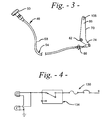
- a device 10 is illustrated for adjusting the speed of a construction machine 14, such as a wheel loader, while increasing the power availability to control an implement 16, such as a bucket.
- the construction machine 14 includes a hydrostatic transmission 18 fluidly connected to a brake apparatus 22.
- the brake apparatus 22 includes a brake cylinder 26 fluidly connected to the hydrostatic transmission 18 in a known manner.
- a brake pedal 30 is located within a operator's compartment 34 of the construction machine 14 in a well-known manner. It should be understood that the construction machine 14 may or may not include a cab as shown in Fig. 1 without limiting the scope of the invention.
- the brake pedal 30 is operatively associated with an operator's foot (not shown) or any other suitable device for rotational movement between first and second positions.
- the brake pedal 30 is connected through a brake shaft 38 to the brake cylinder 26 in a well-known manner.
- the brake shaft 38 is fixedly connected to the brake pedal 30 for movement therewith.
- the brake cylinder 26 has an inching valve 42 operative associated in a known manner with the brake pedal 30 to neutralize the hydrostatic transmission 18 when the brake pedal 30 is moved within a predetermined portion of the movement between the first and the second positions which may approximate ten to fifteen degrees of rotation.
- the inching valve 42 may or may not be integrally connected with the brake cylinder 26 and, therefore, may be separate therefrom without exceeding the scope of the invention.
- a plurality of brake pads are used to stop the construction machine 14 when the brake pedal 30 is moved past the predetermined portion of movement necessary for neutralization of the hydrostatic transmission.
- Control means 46 has a control knob 50 located within the operator's compartment 34 remote from the brake pedal 30 for operation by an operator's hand (not shown) or in any suitable manner.
- the control knob 50 is adjustable within a plurality of positions within a approximate turning range of three rotations.
- a cable mechanism 54 including a cable 58 disposed within a flexible outer housing 62 extends from the control knob 50 and terminates at a clevis connection 66.
- a dog-leg shaped lever assembly 70 is connected at a driven end 74 to the cable 58 at the clevis connection 66 for operation with the control knob 50.
- the lever assembly 70 is mounted for rotation by a bracket 78 to the operator's compartment 34 at a pivot point 82.
- a driving end 86 of the lever assembly 70 has a length approximately twice that of the driven end 74 and is opposite therefrom.
- the driving end 86 is positioned between a lever plate 90 and a curved brake plate 94 and connected therebetween by a pin 98.
- the pivot point 82 is positioned between the driven and driving ends 74,86, respectively, at a location to achieve the least number of turns of the control knob 50 to rotate the lever assembly 70.
- the brake plate 94 is fixedly connected to the brake shaft 38 in any suitable manner, such as through a spring pin (not shown), and moves dependently therewith and has a distal portion 100 extending outwardly from the connection with the brake shaft 38.
- the lever plate 90 is connected to the brake shaft 38 for rotation thereabout and is spaced approximately 10mm from the brake plate 94.
- the pin 98 is fixedly connected on the lever plate 90 in any suitable manner, such as welding, and extends outwardly from a lower portion 102 thereof.
- the pin 98 extends through a defined slot 106 on the driving end 86 of the lever assembly 70 and into a defined slot 110 in the brake plate 94.
- the slot 110 in the brake plate 94 has a arcuate shape with first and second ends 114,118 defining a range of motion for the brake plate 94 to rotate therebetween when the brake pedal 30 is directly applied.
- An electrical circuit 130 is connected to the brake pedal 30 and includes a brake light signal 134 actuated by a switch control (not shown) in a well-known manner, such as through direct application or depression of the brake pedal 30.
- the brake light signal 134 includes a bulb (not shown) which is illuminated when the brake light signal 134 is actuated.
- a brake light cover 138 is connected to the rear of the construction machine 14 in a well-known manner.
- a limit switch 142 which has a non-energized open position and an energized closed position is provided within the electrical circuit 130 between the control switch (not shown) and the brake light signal 134.
- the limit switch 142 is connected to an upper portion 146 of the lever plate 90 and has a contact point 150 which extends outwardly from the lever plate 90 toward the brake plate 94.
- the pin 98 extends from the lever plate 90 through the slot 106 in the lever assembly 70 and into the brake plate 94 so that the pin 98 is abutted against the first end 114 of the slot 110.
- the brake plate 94 is spaced sufficiently from the lever plate 90 to ensure that the distal portion 100 contacts to close and energize the limit switch 142 at the contact point 150 when the pin 98 is abutted against the first end 114 of the slot 110.
- the control knob 50 is turned which rotates the driven end 74 of lever assembly 70 inwardly toward the control knob 50 through the pivot point 82. The rotation of the driven end 74 propels the driving end 86 of the lever assembly 70 opposite the driven end 74.
- a pressure is exerted from the lever assembly 70 against the pin 98 which causes the simultaneous rotation of the lever and the brake plates 90,94, respectively, about the brake shaft 38.
- the direction of movement of the lever assembly 70 and the location of the pin 98 against the first end 114 of the slot 110 provides a constant contact between the brake plate 94 and the contact point 150 of the limit switch 142 throughout the rotation of the lever assembly 70.
- the rotation of the brake plate 94 simultaneously depresses the brake pedal 30 moving it through the predetermined portion of the movement which neutralizes the hydrostatic transmission 18.
- the control knob 50 may be set at any one of the plurality of positions to fix the lever assembly 70 rotation and maintain the brake pedal 30 in any of a plurality of depressed positions within the predetermined portion of movement.
- the ability to depress the brake pedal 30 remotely through the control knob 50 allows an operator to select a ground speed which provides increased hydraulic power availability to the implement through the neutralization of the hydrostatic transmission.
- the ability to maintain the brake pedal 30 at any one of a plurality of positions within the predetermined portion of movement remotely through the control knob 50 increases the operator's freedom of movement.
- the direct application of the brake pedal 30 rotates the brake plate 94 independently from the lever plate 90.
- the brake plate 94 rotates with the brake shaft 38 about the pin 98 within the range of motion allowed by the slot 110 independent from the lever plate 90.
- the independent rotation of the brake plate 94 moves the distal portion 100 thereof out of contact with the limit switch contact point 150 thereby opening and de-energizing the limit switch 142 and permitting actuation of the brake light signal 134.
- the actuation of the brake light signal 134 signifies, by the illumination of the bulb (not shown), that the operator intends to significantly slow or stop the construction machine 14.
Landscapes
- Engineering & Computer Science (AREA)
- Mining & Mineral Resources (AREA)
- Civil Engineering (AREA)
- General Engineering & Computer Science (AREA)
- Structural Engineering (AREA)
- Operation Control Of Excavators (AREA)
- Braking Elements And Transmission Devices (AREA)
Claims (14)
- Ein; eine steuerbares Werkzeug (16) tragende Baumaschine (14) mit einer Benutzerkabine (34), einem hydrostatischen Getriebe (18) und einer einstellbaren Geschwindigkeitssteuervorrichtung (10) für erhöhte Werkzeugsteuerung, wobei die einstellbare Geschwindigkeitssteuervorrichtung (10) Folgendes aufweist:eine Bremsvorrichtung (22) einschließlich eines innerhalb der Benutzerkabine (34) angeordneten zwischen ersten und zweiten Positionen bewegbaren Bremspedals (30), welches durch eine Bremswelle (38) mit einem Bremszylinder (26) in Strömungsmittelverbindung mit dem hydrostatischen Getriebe (18) steht, wobei der Bremszylinder (26) ein mit dem Bremspedal (30) betriebsmäßig assoziiertes Ventil (42) aufweist, und zwar innerhalb eines vorbestimmten Teils der Bewegung zwischen den ersten und zweiten Positionen, um eine ausgewählte Größe der hydrostatischen Getriebeneutralisierung zu erreichen; undSteuermittel (46) verbunden mit dem Bremspedal (30) und angeordnet entfernt davon zur Bewegung des Bremspedals (30) durch den vorbestimmten Teil der Bewegung desselben und zur Beibehaltung des Bremspedals (30) in irgendeiner aus einer Vielzahl von Positionen innerhalb des vorbestimmten Teils der Bewegung um eine ausgewählte Erd- oder Fahrgeschwindigkeit einzustellen und zwar Erhalten aus der ausgewählten Größe der hydrostatischen Getriebeneutralisierung, während des Betriebs der Baumaschine (14).
- Baumaschine (14) nach Anspruch 1, wobei die Bremswelle (38) fest mit dem Bremspedal (30) zur Bewegung damit verbunden ist, und wobei die Steuermittel (46) eine erste Platte (94) aufweisen und zwar fest verbunden mit der Bremswelle (38) zur Bewegung damit, wobei ferner eine zweite Platte (90) mit der Bremswelle (38) verbunden ist, und zwar beabstandet um einen vorbestimmten Abstand von der ersten Platte (94) und ferner mit einer Hebelanordnung (70) verbunden mit den ersten und zweiten Platten (94, 90) an einem ersten Ende (86) durch einen Stift (98) der sich dazwischen erstreckt und mit einem Kabelmechanismus (54) verbunden mit einem zweiten Ende (74) der Hebelanordnung (70) zum Verschwenken der Hebelanordnung (70) innerhalb eines vorbestimmten Bewegungsbereichs um gleichzeitig die ersten und zweiten Platten (94, 90) abhängig um die Bremswelle (38) zu verdrehen, so dass die erste Platte (94) das Bremspedal (30) durch den vorbestimmten Teil der Bewegung zwischen den ersten und zweiten Positionen bewegt.
- Baumaschine (14) nach Anspruch 2, wobei die Bremsvorrichtung (22) eine elektrische Schaltung (130) aufweist, und zwar verbunden mit dem Bremspedal (30) und mit einem Bremslichtsignal (134) betätigt durch das direkte Anlegen des Bremspedals (30) zwischen den ersten und zweiten Positionen und mit einem Grenzschalter (142) angeordnet zwischen dem Bremspedal (30) und dem Bremslichtsignal (134).
- Baumaschine (14) nach Anspruch 2, wobei die Bremsvorrichtung (22) eine elektrische Schaltung (130) aufweist, und zwar verbunden mit dem Bremspedal (30) und mit einem Bremslichtsignal (134) betätigt durch die Bewegung des Bremspedals (30) zwischen den ersten und zweiten Positionen und mit einem Grenzschalter (142) angeordnet zwischen dem Bremspedal (30) und dem Bremslichtsignal (134), und wobei der Grenzschalter (142) mit der zweiten Platte (90) verbunden ist und erregt wird durch Kontakte der ersten Platte (94) um die Betätigung des Bremslichtsignals (134) während der gleichzeitigen Drehung der ersten und zweiten Platten (24, 90) vorgesehen durch die Schwenkbewegung der Hebelanordnung (70) zu übersteuern.
- Baumaschine (14) nach Anspruch 4, wobei der Grenzschalter (142) durch direkte Anlegung des Bremspedals (30) enderregt wird, wobei das Bremspedal (30) die erste Platte (94) außer Kontakt mit dem Grenzschalter (142) bewegt, um die Betätigung des Bremslichtsignals (134) zu gestatten.
- Baumaschine (14) nach Anspruch 5, wobei das direkte Anlegen des Bremspedals (30) die erste Platte (94) unabhängig von der zweiten Platte (90) verdreht.
- Baumaschine (14) nach Anspruch 2, wobei die Hebelanordnung (70) ein Schwenkpunkt (82) aufweist und zwar angeordnet an einer vorbestimmten Position zwischen den ersten und zweiten Enden (86, 74) davon und ferner angeordnet zwischen den ersten und zweiten Platten (94, 90).
- Baumaschine (14) nach Anspruch 7, wobei der Kabelmechanismus (54) ein Kabel (58) aufweist, angeordnet innerhalb des flexiblen äußeren Gehäuses (62) welches sich von einem Steuerknopf (50) erstreckt und zwar einstellbar innerhalb einer Vielzahl von Positionen und endend an einer Clevis- bzw. Schwenkverbindung (66) mit der Hebelanordnung (70), derart, dass dann wenn der Steuerknopf (50) gedreht wird, die Hebelanordnung (70) sich durch den vorbestimmten Bereich der Bewegung verschwenkt und an irgendeiner Stelle festgelegt werden kann und zwar dadurch Einstellen des Steuerknopfes (50) auf irgendeine aus einer Vielzahl von Positionen.
- Baumaschine (14) nach Anspruch 8, wobei der Schwenkpunkt (82) derart angeordnet ist, um ein Laufverhältnis von eins zu drei zu erreichen und zwar vom Steuerknopf (50) zur Hebelanordnung (70).
- Baumaschine (14) nach Anspruch 9, wobei der Steuerknopf (50) geeignet ist, durch die Hand eines Benutzers verdreht zu werden.
- Baumaschine (14) nach Anspruch 6, wobei der Stift (98) fest an der zweiten Platte (90) befestigt ist und sich durch einen definierten Schlitz (106) am ersten Ende der Hebelanordnung (70) erstreckt und sich ferner durch einen definierten Schlitz (110) in der ersten Platte (94) erstreckt, wobei der definierte Schlitz (110) in der ersten Platte (94) erste und zweite Enden (114, 118) aufweist und zwar getrennt durch die Länge davon und einen vorbestimmten Bewegungsbereich definierend.
- Baumaschine (14) nach Anspruch 11, wobei sich der Stift (98) in Anlage mit dem ersten Ende (114) des definierten Schlitzes (110) in der ersten Platte (94) befindet und während des Schwenkes der Hebelanordnung (70) dagegen gehalten wird.
- Baumaschine (14) nach Anspruch 12, wobei die unabhängige Bewegung der ersten Platte (94) von der zweiten Platte (90) vorsieht, dass die erste Platte (94) sich um den Stift (98) längs irgendeiner Vielzahl von Positionen verdreht und zwar längs des vorbestimmten Bereichs der Bewegung gestattet durch den definierten Schlitz (110) in der ersten Platte (94).
- Ein, ein gesteuertes Werkzeug (16) tragende Baumaschine (14), die eine Benutzerkabine (34) aufweist und ferner ein hydrostatisches Getriebe (18) und eine einstellbare Geschwindigkeitssteuervorrichtung (10) zur erhöhten Werkzeugsteuerung, wobei die einstellbare Geschwindigkeitssteuervorrichtung (10) Folgendes aufweist:eine Bremsvorrichtung (22) mit einem Bremspedal (30) angeordnet innerhalb der Fahrkabine (34) und beweglich zwischen ersten und zweiten Positionen wobei das Bremspedal (30) durch eine Bremswelle (38) mit einem Bremszylinder (26) verbunden ist, und zwar in Strömungsmittelverbindung mit dem hydrostatischen Getriebe (18), wobei letzteres ein Ventil (42) aufweist und zwar betriebsmäßig assoziiert mit dem Bremspedal (30) innerhalb eines vorbestimmten Teils der Bewegung zwischen den ersten und zweiten Positionen um eine ausgewählte Größe der hydrostatischen Getriebeneutralisierung zu erreichen; undSteuermittel (46) verbunden mit dem Bremspedal (30) und angeordnet entfernt davon zur Bewegung des Bremspedals (30) durch den vorbestimmten Teil der Bewegung davon und zum Halten des Bremspedals (30) und irgendeiner aus einer Vielzahl von Positionen innerhalb des vorbestimmten Teils der Bewegung um eine ausgewählte Erd- oder Fahrgeschwindigkeit einzustellen und zwar Erhalten aus der ausgewählten Größe der hydrostatischen Getriebeneutralisierung während des Betriebs der Baumaschine (14).
Applications Claiming Priority (2)
| Application Number | Priority Date | Filing Date | Title |
|---|---|---|---|
| US962081 | 1997-10-31 | ||
| US08/962,081 US5941361A (en) | 1997-10-31 | 1997-10-31 | Remote creeper speed control |
Publications (3)
| Publication Number | Publication Date |
|---|---|
| EP0913529A2 EP0913529A2 (de) | 1999-05-06 |
| EP0913529A3 EP0913529A3 (de) | 2000-02-23 |
| EP0913529B1 true EP0913529B1 (de) | 2008-02-13 |
Family
ID=25505395
Family Applications (1)
| Application Number | Title | Priority Date | Filing Date |
|---|---|---|---|
| EP98120498A Expired - Lifetime EP0913529B1 (de) | 1997-10-31 | 1998-10-29 | Fernbediende Regulierung der Kriechgeschwindigkeit |
Country Status (4)
| Country | Link |
|---|---|
| US (1) | US5941361A (de) |
| EP (1) | EP0913529B1 (de) |
| JP (1) | JP4260939B2 (de) |
| DE (1) | DE69839107T2 (de) |
Families Citing this family (4)
| Publication number | Priority date | Publication date | Assignee | Title |
|---|---|---|---|---|
| US9126598B2 (en) * | 2006-06-05 | 2015-09-08 | Deere & Company | Power management for infinitely variable transmission (IVT) equipped machines |
| USD733519S1 (en) * | 2013-10-09 | 2015-07-07 | Security People, Inc. | Electronic locker lock |
| CN111877444B (zh) * | 2020-07-30 | 2022-04-22 | 柳州柳工挖掘机有限公司 | 一种挖掘机电子围墙配置方法、挖掘机控制器及挖掘机 |
| CN112031063A (zh) * | 2020-09-10 | 2020-12-04 | 上海三一重机股份有限公司 | 挖掘机的远程控制系统和方法 |
Family Cites Families (18)
| Publication number | Priority date | Publication date | Assignee | Title |
|---|---|---|---|---|
| US2847875A (en) * | 1955-09-28 | 1958-08-19 | Herbert D Drain | Speed responsive device for automobles |
| US2906141A (en) * | 1955-11-28 | 1959-09-29 | Kocsi Louis | Speed limiting device for vehicles |
| US2853164A (en) * | 1955-12-08 | 1958-09-23 | Harry D Sturdy | Speed control for automotive vehicles |
| US2912880A (en) * | 1957-01-14 | 1959-11-17 | Ralph J Biggs | Speed control device |
| US3050165A (en) * | 1959-08-26 | 1962-08-21 | Caterpillar Tractor Co | System for automatically neutralizing a vehicle transmission upon application of brakes |
| US3000475A (en) * | 1960-03-08 | 1961-09-19 | Leon G Arpin | Speed control for automotive vehicles |
| US3023634A (en) * | 1960-03-15 | 1962-03-06 | Nicholas W Tozza | Automobile speed limiting means |
| US3181666A (en) * | 1962-02-19 | 1965-05-04 | Dow Mechanical Corp | Accelerator controlling device |
| US3181667A (en) * | 1963-02-25 | 1965-05-04 | Caterpillar Tractor Co | System for automatically neutralizing a vehicle transmission upon application of brakes |
| US3999641A (en) * | 1972-08-14 | 1976-12-28 | Caterpillar Tractor Co. | Vehicle transmission neutralizing system |
| GB1427171A (en) * | 1973-02-23 | 1976-03-10 | Shaw & Sons Ltd Joshua | Wheeled vehicles incorporating hydrostatic transmission window frames and parts therefor |
| US4088208A (en) * | 1976-10-26 | 1978-05-09 | International Harvester Company | Transmission disconnect system |
| US4114738A (en) * | 1977-01-17 | 1978-09-19 | Towmotor Corporation | Brake and creeper control system |
| US4246989A (en) * | 1978-12-07 | 1981-01-27 | Caterpillar Tractor Co. | Parking brake and transmission interlock system |
| US4351198A (en) * | 1980-09-12 | 1982-09-28 | Allis-Chalmers Corporation | Hand and foot controlled throttle |
| US5228360A (en) * | 1991-07-26 | 1993-07-20 | The Toro Company | Cruise/speed control system for hydrostatic drive |
| US5203214A (en) * | 1992-04-06 | 1993-04-20 | Case Corporation | Engine throttle linkage with motion-reversing feature |
| KR960005404Y1 (ko) * | 1993-12-28 | 1996-06-28 | 대우중공업 주식회사 | 부스터 브레이크의 파이로트 압력을 이용한 인칭시스템 |
-
1997
- 1997-10-31 US US08/962,081 patent/US5941361A/en not_active Expired - Lifetime
-
1998
- 1998-10-29 EP EP98120498A patent/EP0913529B1/de not_active Expired - Lifetime
- 1998-10-29 DE DE69839107T patent/DE69839107T2/de not_active Expired - Lifetime
- 1998-11-02 JP JP31191598A patent/JP4260939B2/ja not_active Expired - Fee Related
Also Published As
| Publication number | Publication date |
|---|---|
| JP4260939B2 (ja) | 2009-04-30 |
| US5941361A (en) | 1999-08-24 |
| EP0913529A2 (de) | 1999-05-06 |
| JPH11245781A (ja) | 1999-09-14 |
| DE69839107D1 (de) | 2008-03-27 |
| EP0913529A3 (de) | 2000-02-23 |
| DE69839107T2 (de) | 2009-02-12 |
Similar Documents
| Publication | Publication Date | Title |
|---|---|---|
| CA2174011C (en) | Hydraulic control system providing proportional movement to an attachment of a power machine | |
| EP0913529B1 (de) | Fernbediende Regulierung der Kriechgeschwindigkeit | |
| US3868003A (en) | Brake actuated return to neutral mechanism | |
| EP1533208B1 (de) | Lenkradanordnung | |
| US3939937A (en) | Safety apparatus for service vehicle | |
| EP1216876A2 (de) | Bedienerschnittstellensystem | |
| US20050103555A1 (en) | Operator interface system | |
| EP1428094B1 (de) | Fahrzeugpedal mit einstellbarer steuerung | |
| US4936429A (en) | Indexing device for a vehicular steering assembly | |
| US3251492A (en) | Automatic boom positioning device | |
| US7104036B2 (en) | Reverse implement option using reverse pedal | |
| JP2003185006A (ja) | 作業車両の変速制御装置 | |
| JPH0650955U (ja) | 静油圧駆動車における車速コントロール装置 | |
| AU2001293238A1 (en) | Adjustable control vehicle pedal | |
| JP3543791B2 (ja) | 移動農機のブレーキ装置 | |
| JP3591038B2 (ja) | 移動農機におけるブレーキ用アクチュエータの取付構造 | |
| JP4207322B2 (ja) | 作業車両のブレーキ制御装置 | |
| JPH0821266A (ja) | 走行作業機のエンジンコントロール装置 | |
| JP2531296Y2 (ja) | 油圧装置の操作レバー装置 | |
| JPH032038Y2 (de) | ||
| GB2033834A (en) | Seam rubbing and strip applicator machine | |
| JPH0620731Y2 (ja) | 塵芥収集車の制御装置 | |
| JP2001289267A (ja) | 作業車両のクラッチ制御装置 | |
| JPS6410369B2 (de) | ||
| JPH0647701U (ja) | 油圧作業機のエンジン回転制御装置 |
Legal Events
| Date | Code | Title | Description |
|---|---|---|---|
| PUAI | Public reference made under article 153(3) epc to a published international application that has entered the european phase |
Free format text: ORIGINAL CODE: 0009012 |
|
| AK | Designated contracting states |
Kind code of ref document: A2 Designated state(s): DE FR GB |
|
| AX | Request for extension of the european patent |
Free format text: AL;LT;LV;MK;RO;SI |
|
| PUAL | Search report despatched |
Free format text: ORIGINAL CODE: 0009013 |
|
| AK | Designated contracting states |
Kind code of ref document: A3 Designated state(s): AT BE CH CY DE DK ES FI FR GB GR IE IT LI LU MC NL PT SE |
|
| AX | Request for extension of the european patent |
Free format text: AL;LT;LV;MK;RO;SI |
|
| 17P | Request for examination filed |
Effective date: 20000822 |
|
| AKX | Designation fees paid |
Free format text: DE FR GB |
|
| 17Q | First examination report despatched |
Effective date: 20061222 |
|
| GRAP | Despatch of communication of intention to grant a patent |
Free format text: ORIGINAL CODE: EPIDOSNIGR1 |
|
| GRAA | (expected) grant |
Free format text: ORIGINAL CODE: 0009210 |
|
| GRAS | Grant fee paid |
Free format text: ORIGINAL CODE: EPIDOSNIGR3 |
|
| AK | Designated contracting states |
Kind code of ref document: B1 Designated state(s): DE FR GB |
|
| REG | Reference to a national code |
Ref country code: GB Ref legal event code: FG4D |
|
| REF | Corresponds to: |
Ref document number: 69839107 Country of ref document: DE Date of ref document: 20080327 Kind code of ref document: P |
|
| EN | Fr: translation not filed | ||
| PLBE | No opposition filed within time limit |
Free format text: ORIGINAL CODE: 0009261 |
|
| STAA | Information on the status of an ep patent application or granted ep patent |
Free format text: STATUS: NO OPPOSITION FILED WITHIN TIME LIMIT |
|
| 26N | No opposition filed |
Effective date: 20081114 |
|
| PG25 | Lapsed in a contracting state [announced via postgrant information from national office to epo] |
Ref country code: FR Free format text: LAPSE BECAUSE OF FAILURE TO SUBMIT A TRANSLATION OF THE DESCRIPTION OR TO PAY THE FEE WITHIN THE PRESCRIBED TIME-LIMIT Effective date: 20081205 |
|
| GBPC | Gb: european patent ceased through non-payment of renewal fee |
Effective date: 20081029 |
|
| PG25 | Lapsed in a contracting state [announced via postgrant information from national office to epo] |
Ref country code: GB Free format text: LAPSE BECAUSE OF NON-PAYMENT OF DUE FEES Effective date: 20081029 |
|
| PGFP | Annual fee paid to national office [announced via postgrant information from national office to epo] |
Ref country code: DE Payment date: 20151030 Year of fee payment: 18 |
|
| REG | Reference to a national code |
Ref country code: DE Ref legal event code: R119 Ref document number: 69839107 Country of ref document: DE |
|
| PG25 | Lapsed in a contracting state [announced via postgrant information from national office to epo] |
Ref country code: DE Free format text: LAPSE BECAUSE OF NON-PAYMENT OF DUE FEES Effective date: 20170503 |