EP0913556A2 - Refroidissement d'une aube de turbine - Google Patents
Refroidissement d'une aube de turbine Download PDFInfo
- Publication number
- EP0913556A2 EP0913556A2 EP98308829A EP98308829A EP0913556A2 EP 0913556 A2 EP0913556 A2 EP 0913556A2 EP 98308829 A EP98308829 A EP 98308829A EP 98308829 A EP98308829 A EP 98308829A EP 0913556 A2 EP0913556 A2 EP 0913556A2
- Authority
- EP
- European Patent Office
- Prior art keywords
- blade
- cooling
- turbine blade
- side corner
- rearmost
- Prior art date
- Legal status (The legal status is an assumption and is not a legal conclusion. Google has not performed a legal analysis and makes no representation as to the accuracy of the status listed.)
- Withdrawn
Links
- 238000001816 cooling Methods 0.000 title claims abstract description 52
- 239000012530 fluid Substances 0.000 claims 2
- 238000010438 heat treatment Methods 0.000 abstract description 3
- 239000010408 film Substances 0.000 description 6
- 239000007789 gas Substances 0.000 description 6
- 239000000567 combustion gas Substances 0.000 description 5
- 238000005266 casting Methods 0.000 description 4
- POIUWJQBRNEFGX-XAMSXPGMSA-N cathelicidin Chemical compound C([C@@H](C(=O)N[C@@H](CCCNC(N)=N)C(=O)N[C@@H](CCCCN)C(=O)N[C@@H](CO)C(=O)N[C@@H](CCCCN)C(=O)N[C@@H](CCC(O)=O)C(=O)N[C@@H](CCCCN)C(=O)N[C@@H]([C@@H](C)CC)C(=O)NCC(=O)N[C@@H](CCCCN)C(=O)N[C@@H](CCC(O)=O)C(=O)N[C@@H](CC=1C=CC=CC=1)C(=O)N[C@@H](CCCCN)C(=O)N[C@@H](CCCNC(N)=N)C(=O)N[C@@H]([C@@H](C)CC)C(=O)N[C@@H](C(C)C)C(=O)N[C@@H](CCC(N)=O)C(=O)N[C@@H](CCCNC(N)=N)C(=O)N[C@@H]([C@@H](C)CC)C(=O)N[C@@H](CCCCN)C(=O)N[C@@H](CC(O)=O)C(=O)N[C@@H](CC=1C=CC=CC=1)C(=O)N[C@@H](CC(C)C)C(=O)N[C@@H](CCCNC(N)=N)C(=O)N[C@@H](CC(N)=O)C(=O)N[C@@H](CC(C)C)C(=O)N[C@@H](C(C)C)C(=O)N1[C@@H](CCC1)C(=O)N[C@@H](CCCNC(N)=N)C(=O)N[C@@H]([C@@H](C)O)C(=O)N[C@@H](CCC(O)=O)C(=O)N[C@@H](CO)C(O)=O)NC(=O)[C@H](CC=1C=CC=CC=1)NC(=O)[C@H](CC(O)=O)NC(=O)CNC(=O)[C@H](CC(C)C)NC(=O)[C@@H](N)CC(C)C)C1=CC=CC=C1 POIUWJQBRNEFGX-XAMSXPGMSA-N 0.000 description 4
- 239000002826 coolant Substances 0.000 description 3
- PXHVJJICTQNCMI-UHFFFAOYSA-N Nickel Chemical compound [Ni] PXHVJJICTQNCMI-UHFFFAOYSA-N 0.000 description 2
- WYTGDNHDOZPMIW-RCBQFDQVSA-N alstonine Natural products C1=CC2=C3C=CC=CC3=NC2=C2N1C[C@H]1[C@H](C)OC=C(C(=O)OC)[C@H]1C2 WYTGDNHDOZPMIW-RCBQFDQVSA-N 0.000 description 2
- 230000009286 beneficial effect Effects 0.000 description 1
- 230000007423 decrease Effects 0.000 description 1
- 230000003247 decreasing effect Effects 0.000 description 1
- 239000000446 fuel Substances 0.000 description 1
- 239000002184 metal Substances 0.000 description 1
- 229910052751 metal Inorganic materials 0.000 description 1
- 229910052759 nickel Inorganic materials 0.000 description 1
- 238000013021 overheating Methods 0.000 description 1
- 229910000601 superalloy Inorganic materials 0.000 description 1
- 239000010409 thin film Substances 0.000 description 1
- 230000007704 transition Effects 0.000 description 1
Images

Classifications
-
- F—MECHANICAL ENGINEERING; LIGHTING; HEATING; WEAPONS; BLASTING
- F01—MACHINES OR ENGINES IN GENERAL; ENGINE PLANTS IN GENERAL; STEAM ENGINES
- F01D—NON-POSITIVE DISPLACEMENT MACHINES OR ENGINES, e.g. STEAM TURBINES
- F01D5/00—Blades; Blade-carrying members; Heating, heat-insulating, cooling or antivibration means on the blades or the members
- F01D5/12—Blades
- F01D5/14—Form or construction
- F01D5/20—Specially-shaped blade tips to seal space between tips and stator
-
- F—MECHANICAL ENGINEERING; LIGHTING; HEATING; WEAPONS; BLASTING
- F01—MACHINES OR ENGINES IN GENERAL; ENGINE PLANTS IN GENERAL; STEAM ENGINES
- F01D—NON-POSITIVE DISPLACEMENT MACHINES OR ENGINES, e.g. STEAM TURBINES
- F01D5/00—Blades; Blade-carrying members; Heating, heat-insulating, cooling or antivibration means on the blades or the members
- F01D5/12—Blades
- F01D5/14—Form or construction
- F01D5/18—Hollow blades, i.e. blades with cooling or heating channels or cavities; Heating, heat-insulating or cooling means on blades
- F01D5/186—Film cooling
-
- F—MECHANICAL ENGINEERING; LIGHTING; HEATING; WEAPONS; BLASTING
- F01—MACHINES OR ENGINES IN GENERAL; ENGINE PLANTS IN GENERAL; STEAM ENGINES
- F01D—NON-POSITIVE DISPLACEMENT MACHINES OR ENGINES, e.g. STEAM TURBINES
- F01D5/00—Blades; Blade-carrying members; Heating, heat-insulating, cooling or antivibration means on the blades or the members
- F01D5/12—Blades
- F01D5/14—Form or construction
- F01D5/18—Hollow blades, i.e. blades with cooling or heating channels or cavities; Heating, heat-insulating or cooling means on blades
- F01D5/187—Convection cooling
Definitions
- the present invention relates generally to blades in a gas turbine engine, and more particularly to turbine blades having improved cooling features.
- a gas turbine engine includes a compressor for pressurizing air which is channeled to a combustor wherein it is mixed with fuel and ignited for generating hot combustion gas.
- the combustion gas flows downstream through one or more stages of turbine blades which extract energy from the combustion gas for producing useful work.
- Each turbine blade includes a dovetail which mounts the blade to the perimeter of a rotor disk and an integral hollow airfoil extending radially outwardly from the dovetail. Since the turbine blades are directly exposed to the hot combustion gas, they are typically provided with internal cooling circuits which channel a coolant, such as compressor bleed air, through the airfoil of the blade. The coolant exits the airfoil through a number of film cooling holes distributed over the surface thereof, thereby producing a thin film of cooling air which protects the airfoil from the hot combustion gas.
- a coolant such as compressor bleed air
- the aforementioned cooling circuit is typically arranged in a serpentine fashion in which cooling air enters the airfoil at the base, flows radially outwardly to the blade tip through a first passage, then turns 180° into an adjacent passage parallel to the first and flows back toward the base of the airfoil.
- the airflow typically passes through several such passages before finally being exhausted out of the airfoil.
- the cooling passage adjacent to the trailing edge of a turbine blade is a "blind" passage, that is, a passage that does not flow air to another passage in sequence.
- the airflow is maintained primarily through holes in the trailing edge of the blade that communicate with the rearmost cooling passage
- a "dead zone” of reduced airflow can occur in the forward, radially outermost corner of this rearmost cooling passage. This dead zone can lead to localized overheating of the blade which may result in failure of the blade.
- a turbine blade having a base section, a platform section, and an airfoil section.
- the airfoil section has a plurality of internal passages having angled turbulence promoters (or “turbulators”), a plurality of film cooling holes, and a tip cap with a slot near the trailing edge.
- turbulators angled turbulence promoters
- film cooling holes a plurality of film cooling holes
- tip cap with a slot near the trailing edge.
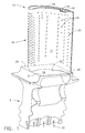
- FIG. 1 shows a turbine blade 10 in accordance with the present invention.
- the blade 10 has a dovetail 12 which mates with matching dovetail features in a turbine rotor, a platform section 14, and a hollow airfoil section 16 with a tip cap 18 that is preferably an integral part of the casting.
- the airfoil has a pressure side 17 and a suction side 19.
- the blade 10 also includes internal cooling passages 22 (see Fig. 2) which channel a coolant such as cooling air through the airfoil section 16 for cooling thereof.
- the pressure side 17 has radial rows of film cooling holes 20 which communicate with the various internal cooling passages of the blade 22 and provide an exit path for cooling air which is introduced through openings 32 in the base of the blade 10.
- the blade 10 is preferably formed as a one-piece casting of the dovetail 12, platform 14, airfoil 16 and tip cap 18 of a suitable high temperature metal such as a nickel-based superalloy which enjoys suitable strength at high temperature operation.
- the platform section 14 of the blade 10 comprises a generally rectangular surface having four corners: a front pressure side corner 24, a rear pressure side corner 26, a front suction side corner 28 and a rear suction side corner 30.
- the platform section 14 of the blade 10 is contoured to improve the flow of hot gas over adjacent blade platforms.
- the front pressure side corner 24 and the rear suction side corner 30 of the platform section 14 are slightly deflected inwardly and the rear pressure side corner 26 and the front suction side corner 28 are slightly deflected outwardly.
- the hot gas entering the turbine stage "steps down" as it passes from one blade platform's front suction side corner 28 to the adjacent blade's front pressure side corner 24 (Fig.
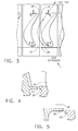
- Fig. 2 illustrates the internal configuration of the blade 10.
- the casting has multiple internal passages 22 arranged in a serpentine fashion for the flow of cooling air.
- the cooling air is introduced into the blade through openings 32 in the dovetail 12 of the blade 10.
- the air then flows around the serpentine passages 22 and out through film cooling holes 20 in the pressure side of the blade 17.
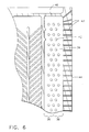
- a rearmost cooling passage 34 is fed through its own opening 32 in the base of the blade 10. Unlike the other passages 22 the rearmost passage 34 is "blind", i.e. the radially outer end of the passage 34 is closed in the sense that the flow passing through it does not enter another cooling passage. As seen in Fig. 6, the rearmost passage 34 can be radially divided into a forward section 36 and a rear section 38.
- the rearmost passage 34 has a bank of cylindrical pins 40 extending from the inner wall of the pressure side 17 to the inner wall of the suction side 19 which promote turbulence and provide additional surface area for heat transfer inside the blade 10.
- the airflow through the rearmost passage 34 is vented to the outside of the blade 10 through film cooling holes 20 on the pressure side 17 of the blade 10, through a radial row of holes 42 in the trailing edge 44 of the blade 10, and through an aperture 46 in the tip cap 18.
- cooling holes 48 are placed on the pressure side 17 of the blade 10 in the radially outer front corner of the rearmost cooling passage 34.
- This additional hole or holes 48 in cooperation with the aperture 46 in the tip cap 18, which is placed substantially in the forward section 36 of the rearmost cooling passage 34, ensures that airflow will continue through the rearmost cooling passage 34 all the way to the radially outer ends eliminating a "dead zone" of little or no air flow in the radially outer front corner of the rearmost cooling passage 34.
- the tip cap aperture 46 is placed as far forward as practicable, substantially in the forward section 36 of the rearmost passage 34.
- the aperture 46 is preferably a non-circular shape so that its area can be larger than that of a circular hole given the width constraints at the narrow rear section of the blade 10.
- the aperture 46 is placed so as to be in communication with the relatively lower pressure airflow outside the blade tip 18. This creates a pressure difference across the aperture 46 which causes the cooling airflow to flow through what would otherwise be a dead zone in the front corner of rearmost cooling passage 34.
- turbulence promoters or turbulators 50 which are slender ribs formed as part of the blade casting on the inside walls of the cooling passages 22.
- the turbulators 50 serve to promote turbulence and increase cooling efficiency of the blade 10. It is beneficial in blade design to maintain as low a pressure drop and as high a heat transfer rate as possible. An improvement, i.e. reduction, in pressure drop can be expected with angled turbulators. Since the pressure drop is proportional to the friction factor, decreasing turbulator angle from 90° to the direction of flow reduces flow resistance or friction thereby reducing pressure drop. However, as turbulators are angled away from 90° to the flow, the rate of heat transfer also decreases.
- the turbulators 50 are placed at a non-perpendicular angle to the flow to obtain a compromise between optimum heat transfer and minimum flow losses.
- the non-perpendicular angle is preferably in the range of about 40° to about 90°.
Landscapes
- Engineering & Computer Science (AREA)
- Mechanical Engineering (AREA)
- General Engineering & Computer Science (AREA)
- Turbine Rotor Nozzle Sealing (AREA)
Applications Claiming Priority (2)
| Application Number | Priority Date | Filing Date | Title |
|---|---|---|---|
| US96212897A | 1997-10-31 | 1997-10-31 | |
| US962128 | 1997-10-31 |
Publications (2)
| Publication Number | Publication Date |
|---|---|
| EP0913556A2 true EP0913556A2 (fr) | 1999-05-06 |
| EP0913556A3 EP0913556A3 (fr) | 2000-07-26 |
Family
ID=25505455
Family Applications (1)
| Application Number | Title | Priority Date | Filing Date |
|---|---|---|---|
| EP98308829A Withdrawn EP0913556A3 (fr) | 1997-10-31 | 1998-10-28 | Refroidissement d'une aube de turbine |
Country Status (2)
| Country | Link |
|---|---|
| EP (1) | EP0913556A3 (fr) |
| JP (1) | JPH11193701A (fr) |
Cited By (8)
| Publication number | Priority date | Publication date | Assignee | Title |
|---|---|---|---|---|
| EP1111190A1 (fr) * | 1999-12-18 | 2001-06-27 | General Electric Company | Aube de turbine refroidie avec turbulateurs inclinés ou en forme de V |
| US6579061B1 (en) | 2001-07-27 | 2003-06-17 | General Electric Company | Selective step turbine nozzle |
| US6672832B2 (en) | 2002-01-07 | 2004-01-06 | General Electric Company | Step-down turbine platform |
| US7097429B2 (en) | 2004-07-13 | 2006-08-29 | General Electric Company | Skirted turbine blade |
| US7121802B2 (en) | 2004-07-13 | 2006-10-17 | General Electric Company | Selectively thinned turbine blade |
| EP1731710A1 (fr) * | 2005-06-06 | 2006-12-13 | General Electric Company | Aube de turbine avec refroidissement par impact intégré et circuit de refroidissement en serpentin |
| EP1760267A2 (fr) | 2005-08-31 | 2007-03-07 | General Electric Company | Aube refroidie de turbine |
| CN104420893A (zh) * | 2013-08-30 | 2015-03-18 | 通用电气公司 | 具有多孔冷却特征的燃气涡轮机部件 |
Families Citing this family (3)
| Publication number | Priority date | Publication date | Assignee | Title |
|---|---|---|---|---|
| US6652235B1 (en) * | 2002-05-31 | 2003-11-25 | General Electric Company | Method and apparatus for reducing turbine blade tip region temperatures |
| US7946816B2 (en) * | 2008-01-10 | 2011-05-24 | General Electric Company | Turbine blade tip shroud |
| JP7224928B2 (ja) * | 2019-01-17 | 2023-02-20 | 三菱重工業株式会社 | タービン動翼及びガスタービン |
Family Cites Families (8)
| Publication number | Priority date | Publication date | Assignee | Title |
|---|---|---|---|---|
| US4135857A (en) * | 1977-06-09 | 1979-01-23 | United Technologies Corporation | Reduced drag airfoil platforms |
| US4278400A (en) * | 1978-09-05 | 1981-07-14 | United Technologies Corporation | Coolable rotor blade |
| JPS62228603A (ja) * | 1986-03-31 | 1987-10-07 | Toshiba Corp | ガスタ−ビンの翼 |
| US4753575A (en) * | 1987-08-06 | 1988-06-28 | United Technologies Corporation | Airfoil with nested cooling channels |
| GB2250548A (en) * | 1990-12-06 | 1992-06-10 | Rolls Royce Plc | Cooled turbine aerofoil blade |
| JP3006174B2 (ja) * | 1991-07-04 | 2000-02-07 | 株式会社日立製作所 | 内部に冷却通路を有する部材 |
| US5243759A (en) * | 1991-10-07 | 1993-09-14 | United Technologies Corporation | Method of casting to control the cooling air flow rate of the airfoil trailing edge |
| US5387085A (en) * | 1994-01-07 | 1995-02-07 | General Electric Company | Turbine blade composite cooling circuit |
-
1998
- 1998-10-27 JP JP30466498A patent/JPH11193701A/ja active Pending
- 1998-10-28 EP EP98308829A patent/EP0913556A3/fr not_active Withdrawn
Non-Patent Citations (1)
| Title |
|---|
| None |
Cited By (13)
| Publication number | Priority date | Publication date | Assignee | Title |
|---|---|---|---|---|
| EP1111190A1 (fr) * | 1999-12-18 | 2001-06-27 | General Electric Company | Aube de turbine refroidie avec turbulateurs inclinés ou en forme de V |
| US6579061B1 (en) | 2001-07-27 | 2003-06-17 | General Electric Company | Selective step turbine nozzle |
| EP1279796A3 (fr) * | 2001-07-27 | 2003-12-03 | General Electric Company | Tuyère étagée pour turbine |
| US6672832B2 (en) | 2002-01-07 | 2004-01-06 | General Electric Company | Step-down turbine platform |
| US7097429B2 (en) | 2004-07-13 | 2006-08-29 | General Electric Company | Skirted turbine blade |
| US7121802B2 (en) | 2004-07-13 | 2006-10-17 | General Electric Company | Selectively thinned turbine blade |
| EP1731710A1 (fr) * | 2005-06-06 | 2006-12-13 | General Electric Company | Aube de turbine avec refroidissement par impact intégré et circuit de refroidissement en serpentin |
| US7377747B2 (en) | 2005-06-06 | 2008-05-27 | General Electric Company | Turbine airfoil with integrated impingement and serpentine cooling circuit |
| EP1760267A2 (fr) | 2005-08-31 | 2007-03-07 | General Electric Company | Aube refroidie de turbine |
| US7249934B2 (en) | 2005-08-31 | 2007-07-31 | General Electric Company | Pattern cooled turbine airfoil |
| EP1760267A3 (fr) * | 2005-08-31 | 2009-06-10 | General Electric Company | Aube refroidie de turbine |
| CN1970997B (zh) * | 2005-08-31 | 2012-04-25 | 通用电气公司 | 图案化冷却的涡轮机翼型部 |
| CN104420893A (zh) * | 2013-08-30 | 2015-03-18 | 通用电气公司 | 具有多孔冷却特征的燃气涡轮机部件 |
Also Published As
| Publication number | Publication date |
|---|---|
| JPH11193701A (ja) | 1999-07-21 |
| EP0913556A3 (fr) | 2000-07-26 |
Similar Documents
| Publication | Publication Date | Title |
|---|---|---|
| EP1008724B1 (fr) | Aube de moteur à turbine à gaz | |
| US6099252A (en) | Axial serpentine cooled airfoil | |
| EP1327747B1 (fr) | Bord de fuite d'aube de turbine refroidi par impact | |
| EP1496204B1 (fr) | Aube de turbine | |
| JP4576177B2 (ja) | 収束ピン冷却式翼形部 | |
| CA2668605C (fr) | Profil aerodynamique de turbine a ecoulement transversal | |
| EP1473439B1 (fr) | Aube crénelée refroidie pour turbine | |
| EP1445424B1 (fr) | Aube creuse avec circuit incorporé pour le refroidissement des extrémités | |
| JP3459579B2 (ja) | 後方流動多段エーロフォイル冷却回路 | |
| US5207556A (en) | Airfoil having multi-passage baffle | |
| CA2327857C (fr) | Distributeur de turbine a refroidissement par film oblique | |
| US6471479B2 (en) | Turbine airfoil with single aft flowing three pass serpentine cooling circuit | |
| EP1035302A2 (fr) | Aube de turbomachine refroidie par impact multiple de jet d'air | |
| EP1001136B1 (fr) | Aube pour turbomachine avec refroidissement séparé du bord d'attaque | |
| EP1001135A2 (fr) | Aube de turbomachine refroidie par impact en cascade | |
| EP0913556A2 (fr) | Refroidissement d'une aube de turbine | |
| EP1362982B1 (fr) | Aube de turbine avec des canaux de refroidissement de serpentin triple dirigé vers l'arrière |
Legal Events
| Date | Code | Title | Description |
|---|---|---|---|
| PUAI | Public reference made under article 153(3) epc to a published international application that has entered the european phase |
Free format text: ORIGINAL CODE: 0009012 |
|
| AK | Designated contracting states |
Kind code of ref document: A2 Designated state(s): DE FR GB IT |
|
| AX | Request for extension of the european patent |
Free format text: AL;LT;LV;MK;RO;SI |
|
| PUAL | Search report despatched |
Free format text: ORIGINAL CODE: 0009013 |
|
| AK | Designated contracting states |
Kind code of ref document: A3 Designated state(s): AT BE CH CY DE DK ES FI FR GB GR IE IT LI LU MC NL PT SE |
|
| AX | Request for extension of the european patent |
Free format text: AL;LT;LV;MK;RO;SI |
|
| 17P | Request for examination filed |
Effective date: 20010126 |
|
| AKX | Designation fees paid |
Free format text: DE FR GB IT |
|
| STAA | Information on the status of an ep patent application or granted ep patent |
Free format text: STATUS: THE APPLICATION HAS BEEN WITHDRAWN |
|
| 18W | Application withdrawn |
Withdrawal date: 20010405 |