EP0913653B1 - Méthode de construction d'une installation cryogénique par éléments préassemblés - Google Patents
Méthode de construction d'une installation cryogénique par éléments préassemblés Download PDFInfo
- Publication number
- EP0913653B1 EP0913653B1 EP98402535A EP98402535A EP0913653B1 EP 0913653 B1 EP0913653 B1 EP 0913653B1 EP 98402535 A EP98402535 A EP 98402535A EP 98402535 A EP98402535 A EP 98402535A EP 0913653 B1 EP0913653 B1 EP 0913653B1
- Authority
- EP
- European Patent Office
- Prior art keywords
- column
- internal structure
- frame
- equipment
- package
- Prior art date
- Legal status (The legal status is an assumption and is not a legal conclusion. Google has not performed a legal analysis and makes no representation as to the accuracy of the status listed.)
- Expired - Lifetime
Links
Images


Classifications
-
- F—MECHANICAL ENGINEERING; LIGHTING; HEATING; WEAPONS; BLASTING
- F25—REFRIGERATION OR COOLING; COMBINED HEATING AND REFRIGERATION SYSTEMS; HEAT PUMP SYSTEMS; MANUFACTURE OR STORAGE OF ICE; LIQUEFACTION SOLIDIFICATION OF GASES
- F25J—LIQUEFACTION, SOLIDIFICATION OR SEPARATION OF GASES OR GASEOUS OR LIQUEFIED GASEOUS MIXTURES BY PRESSURE AND COLD TREATMENT OR BY BRINGING THEM INTO THE SUPERCRITICAL STATE
- F25J3/00—Processes or apparatus for separating the constituents of gaseous or liquefied gaseous mixtures involving the use of liquefaction or solidification
- F25J3/02—Processes or apparatus for separating the constituents of gaseous or liquefied gaseous mixtures involving the use of liquefaction or solidification by rectification, i.e. by continuous interchange of heat and material between a vapour stream and a liquid stream
- F25J3/04—Processes or apparatus for separating the constituents of gaseous or liquefied gaseous mixtures involving the use of liquefaction or solidification by rectification, i.e. by continuous interchange of heat and material between a vapour stream and a liquid stream for air
- F25J3/04763—Start-up or control of the process; Details of the apparatus used
- F25J3/04866—Construction and layout of air fractionation equipments, e.g. valves, machines
- F25J3/04945—Details of internal structure; insulation and housing of the cold box
-
- F—MECHANICAL ENGINEERING; LIGHTING; HEATING; WEAPONS; BLASTING
- F25—REFRIGERATION OR COOLING; COMBINED HEATING AND REFRIGERATION SYSTEMS; HEAT PUMP SYSTEMS; MANUFACTURE OR STORAGE OF ICE; LIQUEFACTION SOLIDIFICATION OF GASES
- F25J—LIQUEFACTION, SOLIDIFICATION OR SEPARATION OF GASES OR GASEOUS OR LIQUEFIED GASEOUS MIXTURES BY PRESSURE AND COLD TREATMENT OR BY BRINGING THEM INTO THE SUPERCRITICAL STATE
- F25J3/00—Processes or apparatus for separating the constituents of gaseous or liquefied gaseous mixtures involving the use of liquefaction or solidification
- F25J3/02—Processes or apparatus for separating the constituents of gaseous or liquefied gaseous mixtures involving the use of liquefaction or solidification by rectification, i.e. by continuous interchange of heat and material between a vapour stream and a liquid stream
- F25J3/04—Processes or apparatus for separating the constituents of gaseous or liquefied gaseous mixtures involving the use of liquefaction or solidification by rectification, i.e. by continuous interchange of heat and material between a vapour stream and a liquid stream for air
- F25J3/04763—Start-up or control of the process; Details of the apparatus used
- F25J3/04866—Construction and layout of air fractionation equipments, e.g. valves, machines
- F25J3/0489—Modularity and arrangement of parts of the air fractionation unit, in particular of the cold box, e.g. pre-fabrication, assembling and erection, dimensions, horizontal layout "plot"
-
- B—PERFORMING OPERATIONS; TRANSPORTING
- B01—PHYSICAL OR CHEMICAL PROCESSES OR APPARATUS IN GENERAL
- B01J—CHEMICAL OR PHYSICAL PROCESSES, e.g. CATALYSIS OR COLLOID CHEMISTRY; THEIR RELEVANT APPARATUS
- B01J2219/00—Chemical, physical or physico-chemical processes in general; Their relevant apparatus
- B01J2219/32—Details relating to packing elements in the form of grids or built-up elements for forming a unit of module inside the apparatus for mass or heat transfer
- B01J2219/322—Basic shape of the elements
- B01J2219/32203—Sheets
- B01J2219/32275—Mounting or joining of the blocks or sheets within the column or vessel
-
- F—MECHANICAL ENGINEERING; LIGHTING; HEATING; WEAPONS; BLASTING
- F25—REFRIGERATION OR COOLING; COMBINED HEATING AND REFRIGERATION SYSTEMS; HEAT PUMP SYSTEMS; MANUFACTURE OR STORAGE OF ICE; LIQUEFACTION SOLIDIFICATION OF GASES
- F25J—LIQUEFACTION, SOLIDIFICATION OR SEPARATION OF GASES OR GASEOUS OR LIQUEFIED GASEOUS MIXTURES BY PRESSURE AND COLD TREATMENT OR BY BRINGING THEM INTO THE SUPERCRITICAL STATE
- F25J2290/00—Other details not covered by groups F25J2200/00 - F25J2280/00
- F25J2290/42—Modularity, pre-fabrication of modules, assembling and erection, horizontal layout, i.e. plot plan, and vertical arrangement of parts of the cryogenic unit, e.g. of the cold box
-
- Y—GENERAL TAGGING OF NEW TECHNOLOGICAL DEVELOPMENTS; GENERAL TAGGING OF CROSS-SECTIONAL TECHNOLOGIES SPANNING OVER SEVERAL SECTIONS OF THE IPC; TECHNICAL SUBJECTS COVERED BY FORMER USPC CROSS-REFERENCE ART COLLECTIONS [XRACs] AND DIGESTS
- Y10—TECHNICAL SUBJECTS COVERED BY FORMER USPC
- Y10T—TECHNICAL SUBJECTS COVERED BY FORMER US CLASSIFICATION
- Y10T29/00—Metal working
- Y10T29/49—Method of mechanical manufacture
- Y10T29/49826—Assembling or joining
- Y10T29/49904—Assembling a subassembly, then assembling with a second subassembly
-
- Y—GENERAL TAGGING OF NEW TECHNOLOGICAL DEVELOPMENTS; GENERAL TAGGING OF CROSS-SECTIONAL TECHNOLOGIES SPANNING OVER SEVERAL SECTIONS OF THE IPC; TECHNICAL SUBJECTS COVERED BY FORMER USPC CROSS-REFERENCE ART COLLECTIONS [XRACs] AND DIGESTS
- Y10—TECHNICAL SUBJECTS COVERED BY FORMER USPC
- Y10T—TECHNICAL SUBJECTS COVERED BY FORMER US CLASSIFICATION
- Y10T29/00—Metal working
- Y10T29/53—Means to assemble or disassemble
- Y10T29/53443—Means to assemble or disassemble container and fluid component
Definitions
- the present invention relates to a method of making of a package per assembly according to the preamble of claim 1.
- the invention applies in particular to the production a package of an air distillation column surrounded of its support frame and equipped with its equipment functional.
- the pre-assembly in a package of a column, its support structure and its functional equipment allows to simplify such an installation. Indeed, such package is usually made in the workshop, then transported on the installation site where the number of operations to be performed is then limited.
- This pre-assembly is particularly interesting, for example, when the industrial site is subject to harsh weather conditions, or when is very far from the company's locations installing the column.
- the column not equipped in the frame one of the large side faces of which is entirely clear, to allow access to the different bodies of profession who then come to make the necessary connections and the installation of equipment.
- the invention aims to solve the problems previously mentioned by providing a method of making simpler, more economical, faster and to limit security problems and assembly errors.
- the subject of the invention is a method according to claim 1.
- the invention finally relates to a construction method on site of an assembly comprising a structure internal fluid containment intended to form the less part of a fluid supply installation, an exterior structure surrounding the interior structure, and functional equipment assembled at least on the interior structure, this assembly having a longitudinal axis, notably substantially vertical, characterized in what we erect on the site a package made as described above.
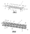
- Figures 1 and 2 show a column of air distillation 1 and its support frame 2 before assembly to make a package.
- Column 1 of generally cylindrical axis ⁇ 1, includes a main distillation section 3 and a additional distillation section 4 or "minaret" in diameter notably weaker, which extends the main stretch 3 at its upper end (on the left in FIG. 1).
- the main section 3 comprises the medium pressure part, the low pressure part and the main vaporizer-condenser.
- Column 1 has, for example, a length of about 15 meters.
- This column 1 rests on two transverse cradles support 5 spaced apart and whose longitudinal positions are as described below.
- cradles 5 are provided with roller skates 6 axes transverse to column 1.
- a metal belt protection 7 surrounds the column at each cradle 5.
- Frame 2 is a metal frame of general parallelepiped shape with four posts longitudinal 8 connected, on each large lateral face of the frame 2, by crosspieces 9 and braces diagonals 10.
- the median longitudinal axis of the frame 2 is referenced ⁇ 2 and is arranged horizontally.
- This frame 2 rests on four feet 11 of adjustable height.
- column 1 has been pre-equipped and frame 2 for the production of a package.
- column 1 is pre-equipped on its surface exterior of a phase separator pot 12 and its pipe liquid nitrogen outlet 13, a reflux line 14 liquid, heat exchanger 15 and its pipe liquid supply 16, and finally a pipe gas outlet 17.
- the separator pot 12 can also be connected to a nitrogen gas outlet pipe (not shown).
- the separator pot 12 has a generally cylindrical shape and it is fixed to column 1 with its axis substantially parallel to the axis ⁇ 1.
- the pot 12 is connected at the level of its lower part (right in figure 1) to its outlet pipe 13, which was fixed on column 1.
- This pipe 13 comprises a main part 18 rectilinear, of axis arranged parallel to the axis ⁇ 1, and connected to the pot 12, and a part in U 19 connection to the outside, substantially transverse in column 1, and extending part 18.
- this separator pot 12 allows the production of free liquid which will be brought through line 13 to external storage elements to the column.
- the liquid reflux line 14 is fixed to the column 1 and includes a main straight part 20 axis arranged parallel to the axis ⁇ 1 and a U-shaped part 21 connection, substantially transverse to column 1.
- Part 20 is connected by one end to section 3 and by another end to part 21.
- the heat exchanger 15 has a generally cylindrical shape and it is fixed to column 1 with its axis substantially parallel to the axis ⁇ 1.
- the exchanger 15 is connected at the level of its part lower than its liquid supply line 16, than it was fixed on column 1.
- This pipe 16 comprises a rectilinear main part 22 of axis arranged parallel to the ⁇ 1 axis, and connected to the exchanger 15, and a part in U 23 connection, substantially transverse to the column 1 and extending part 22.
- the gas outlet pipe 17 is connected to the head (on the left in figure 1) of the additional section 4 of column 1 via an elbow portion 24. This pipe 17 is fixed along the outer surface of column 1 parallel to the axis ⁇ 1.
- the pot 12, the lines 13, 14, 16 and 17, and the exchanger 15 are intended to be crossed by fluids whose temperatures are significantly lower than the frame temperature 2, i.e. at temperature ambient at the site where the column is to be installed.
- Frame 2 is pre-equipped with an interior ladder 25, rails 26 for threading column 1, a path instrumentation 27, and a protective sheet metal shown for clarity of description.
- the ladder 25 is arranged longitudinally at inside of frame 2, on one of the large side faces of frame 2, referenced 28. It is intended to allow access to the packet when it is erected on site as described below.
- the rails 26 are longitudinal rails arranged inside the frame 2 on the transport face 29 (below in Figure 2) of the frame 2.
- the instrumentation path 27 includes, fixed on a longitudinal support plate, pipes instrumentation, instrumentation cables and a pipe gas supply, shown schematically for the clarity of the figures.
- Instrumentation path 27 is a functional equipment to control operation from the distillation column 1 on site.
- the pipes instrumentation include sampling lines of fluid.
- the gas supply line allows to supply a gas to keep an insulator out of humidity which is placed between column 1 and frame 2 as described further.
- the instrumentation path 27 and in particular its support plate are meant to contract significantly less than the equipment attached to column 1 when operation of the latter.
- Frame 2 is also covered to the maximum of its protective sheet metal.
- this sheet metal work is arranged outside on all sides of the frame, except on face 29 and on bottom 30 of the frame (right in Figure 2).
- This sheet metal is intended for form a protective and thermal insulation envelope of the column.
- column 1 in the frame 2 by threading, by rolling the pads 6 on the rails 26, using a winch 31 connected by a cable to the upper end (at left in Figure 3) of column 1.
- a vertical cylinder 32 is disposed between the column 1 and a cross member 9 of the large upper side face (on the Figure 5) of the frame 2, and two horizontal cylinders 32 are each arranged between column 1 and a cross 9 a large vertical lateral face (in FIG. 5) of the frame 2.
- the inner ends of these three cylinders 32 are supported and welded to the surrounding belt 7 column 1 and their outer ends are fixed on the associated crosspieces 9 of the frame 2.
- Two vertical cylinders 32 are further arranged between the underside of the cradle 5 and a cross member 9 of the face 29 of the frame 2. Their upper ends are attached to cradle 5 and their lower ends on the frame 2. Then remove the pads 6 under the two cradles 5, as shown in Figure 5. We position then column 1 in relation to frame 2 so that their axes ⁇ 1 and ⁇ 2 are parallel and have a desired relative position. The relative position of these two axes can be determined using a sighting device or using another classic technique to the skilled person.
- This relative position can be changed by playing on the adjustment of the jacks 32.
- column 1 is arranged substantially in a central position of the frame 2, that is to say such that ⁇ 1 and ⁇ 2 are substantially combined and define the longitudinal axis of the package 33.
- a conventional insulator is then placed between the column 1 and the frame 2.
- the package 33 is then ready to be transported on an industrial site. Once on site, we erect the package 33 along its longitudinal axis using lifting means.
- the lower ends (on the right in the figure 4) longitudinal posts 8 are arranged on feet adjustable height. Thanks, for example, to a sighting or another conventional technique of the skilled person, the verticality of the axis ⁇ 2 is ensured.
- the axis ⁇ 1 of column 1 being parallel to the axis ⁇ 2 of frame 2, by modifying the respective height of feet on which the frame 2 rests, it is easily ensured the verticality of column 1 necessary for its proper functioning.
- the pre-equipment of the column and the frame according to the invention allows different trades to work in parallel on these two structures without getting in the way, the order of installation of the equipment on the frame and on the column being free unlike the case of the processes classic packet making.
- the number of access openings in the frame is limited compared to conventional packages, this which limits the disassembly / reassembly operations of the frame and allows to install in advance the protective sheet metal on three large lateral faces of the frame at instead of two in general according to conventional methods.
- the frames used for the implementation of the process according to the invention are, for this reason, more rigid and therefore more easily transportable than in traditional methods of making packages.
- the exterior structure can be a thermal insulation structure and the structure interior can be for example a cryogenic tank, i.e. containing a fluid at a lower temperature at least about 100 ° C at room temperature.
- the method can also be implemented according to the invention for making section packages of interior and exterior structures, interior structure then being, for example, a section of a column and the exterior structure then being a section of frame corresponding.
Landscapes
- Engineering & Computer Science (AREA)
- Physics & Mathematics (AREA)
- Mechanical Engineering (AREA)
- Thermal Sciences (AREA)
- General Engineering & Computer Science (AREA)
- Separation By Low-Temperature Treatments (AREA)
- Filling Or Discharging Of Gas Storage Vessels (AREA)
- Sewage (AREA)
- Conveying And Assembling Of Building Elements In Situ (AREA)
Description
- on pré-équipe avec au moins une partie d'au moins un équipement fonctionnel la structure extérieure avant enfilage dans cette dernière de la structure intérieure,
- la structure intérieure étant une structure de confinement d'au moins un fluide de température notablement différente de celle de la structure extérieure, on pré-équipe la structure extérieure avec au moins une partie d'au moins un équipement destinée à être sensiblement en équilibre thermique avec celle-ci,
- la structure intérieure étant une structure de confinement d'au moins un fluide de température notablement différente de celle de la structure extérieure, on pré-équipe la structure intérieure avec au moins une partie d'un équipement destinée à être sensiblement en équilibre thermique avec ledit fluide,
- on enfile la structure intérieure dans la structure extérieure en la déplaçant sur des rails prévus dans la structure extérieure disposée sensiblement horizontalement, et
- la structure extérieure est au moins un tronçon d'une charpente de support de la structure intérieure.
- les figures 1 et 2 sont des vues en perspective, illustrant respectivement une colonne de distillation et sa charpente de support pré-équipées selon l'invention,
- les figures 3 et 4 sont des vues en perspective, illustrant deux phases successives de l'enfilage de la colonne de la figure 1 dans la charpente de la figure 2, et
- la figure 5 est une vue schématique en coupe transversale de la colonne et de la charpente de la figure 4, illustrant le positionnement de la colonne par rapport à la charpente.
Claims (7)
- Procédé de réalisation d'un paquet (33) par assemblage d'une structure intérieure (1) qui est au moins un tronçon d'une colonne de distillation cryogénique, d'une structure extérieure (2), qui est au moins un tronçon d'une enveloppe d'isolation thermique, entourant la structure intérieure, et des équipements fonctionnels (12, 13, 14, 15, 16, 17, 27) au moins sur la structure intérieure (1), la structure intérieure (1) étant destinée à former au moins une partie d'une installation de fourniture de fluide, dans lequel on pré-équipe au moins la structure intérieure (1) avec au moins une partie d'au moins un équipement fonctionnel avant l'assemblage du paquet caractérisé en ce que l'on introduit la structure intérieure pré-équippée dans la structure extérieure (2) par enfilage selon un axe longitudinal du paquet (33).
- Procédé selon la revendication 1, caractérisé en ce qu'on pré-équipe avec au moins une partie d'au moins un équipement fonctionnel la structure extérieure (2) avant enfilage dans cette dernière de la structure intérieure (1).
- Procédé selon la revendication 2, caractérisé en ce que la structure intérieure (1) étant une structure de confinement d'au moins un fluide de température notablement différente de celle de la structure extérieure, on pré-équipe la structure extérieure avec au moins une partie d'au moins un équipement (27) destinée à être sensiblement en équilibre thermique avec celle-ci.
- Procédé selon l'une quelconque des revendications 1 à 3, caractérisé en ce que la structure intérieure (1) étant une structure de confinement d'au moins un fluide de température notablement différente de celle de la structure extérieure, on pré-équipe la structure intérieure avec au moins une partie d'un équipement destinée (12, 13, 14, 15, 16, 17) à être sensiblement en équilibre thermique avec ledit fluide.
- Procédé selon l'une quelconque des revendications 1 à 4, caractérisé en ce qu'on enfile la structure intérieure (1) dans la structure extérieure (2) en la déplaçant sur des rails (26) prévus dans la structure extérieure (2) disposée sensiblement horizontalement.
- Procédé selon l'une quelconque des revendications 1 à 5, caractérisé en ce que la structure extérieure est au moins un tronçon d'une charpente de support de la structure intérieure.
- Procédé de construction sur site d'un assemblage comprenant une structure intérieure de confinement de fluide (1) destinée à former au moins une partie d'une installation de fourniture de fluide, une structure extérieure (2) entourant la structure intérieure, et des équipements fonctionnels (12, 13, 14, 15, 16, 17, 27) assemblés au moins sur la structure intérieure (1), cet assemblage présentant un axe longitudinal, notamment sensiblement vertical, caractérisé en ce qu'on érige sur le site un paquet (33) réalisé selon l'une quelconque des revendications 1 à 6.
Applications Claiming Priority (2)
| Application Number | Priority Date | Filing Date | Title |
|---|---|---|---|
| FR9712840A FR2769656B1 (fr) | 1997-10-14 | 1997-10-14 | Procede de realisation d'un paquet par assemblage d'une structure interieure de confinement de fluide, d'une structure exterieure et d'equipements, et procede de construction sur site utilisant un tel paquet |
| FR9712840 | 1997-10-14 |
Publications (3)
| Publication Number | Publication Date |
|---|---|
| EP0913653A1 EP0913653A1 (fr) | 1999-05-06 |
| EP0913653B1 true EP0913653B1 (fr) | 2003-05-21 |
| EP0913653B2 EP0913653B2 (fr) | 2007-03-28 |
Family
ID=9512211
Family Applications (1)
| Application Number | Title | Priority Date | Filing Date |
|---|---|---|---|
| EP98402535A Expired - Lifetime EP0913653B2 (fr) | 1997-10-14 | 1998-10-13 | Méthode de construction d'une installation cryogénique par éléments préassemblés |
Country Status (12)
| Country | Link |
|---|---|
| US (1) | US6711868B1 (fr) |
| EP (1) | EP0913653B2 (fr) |
| JP (1) | JP4248632B2 (fr) |
| KR (1) | KR19990037046A (fr) |
| CN (1) | CN1216819A (fr) |
| AR (1) | AR016959A1 (fr) |
| AU (1) | AU736839B2 (fr) |
| BR (1) | BR9803895A (fr) |
| CA (1) | CA2249888C (fr) |
| DE (1) | DE69814792T3 (fr) |
| FR (1) | FR2769656B1 (fr) |
| ZA (1) | ZA989248B (fr) |
Families Citing this family (18)
| Publication number | Priority date | Publication date | Assignee | Title |
|---|---|---|---|---|
| FR2799822B1 (fr) * | 1999-10-18 | 2002-03-29 | Air Liquide | Boite froide, installation de distillation d'air et procede de construction correspondants |
| DE10040391A1 (de) * | 2000-08-18 | 2002-02-28 | Linde Ag | Tieftemperaturluftzerlegungsanlage |
| US6691532B2 (en) | 2001-11-13 | 2004-02-17 | The Boc Group, Inc. | Air separation units |
| GB2398516A (en) * | 2003-02-18 | 2004-08-25 | Air Prod & Chem | Distillation column with a surrounding insulating support structure |
| EP2009378B1 (fr) | 2007-06-26 | 2018-08-08 | Linde AG | Procédé de montage d'une installation de séparation de gaz |
| DE102008024505A1 (de) | 2007-06-26 | 2009-01-02 | Linde Ag | Montage einer Anlage zur Gaszerlegung |
| JP5354972B2 (ja) * | 2007-06-26 | 2013-11-27 | リンデ アクチエンゲゼルシャフト | 気体分離設備の組立方法 |
| US9187194B2 (en) * | 2013-05-24 | 2015-11-17 | L'Air Liquide Société Anonyme Pour L'Étude Et L'Exploitation Des Procedes Georges Claude | System for distributing the weight of a column section |
| FR3052244B1 (fr) | 2016-06-06 | 2018-05-18 | L'air Liquide, Societe Anonyme Pour L'etude Et L'exploitation Des Procedes Georges Claude | Procede de construction ou de modification d'un appareil d'echange de matiere et/ou de chaleur |
| WO2018130157A1 (fr) * | 2017-01-10 | 2018-07-19 | L'air Liquide, Societe Anonyme Pour L'etude Et L'exploitation Des Procedes Georges Claude | Enceinte pour appareil de séparation d'un mélange gazeux par distillation, et appareil de séparation comprenant une telle enceinte |
| WO2018140445A1 (fr) * | 2017-01-25 | 2018-08-02 | Praxair Technology, Inc. | Ensemble support structurel pour structures de boîte froide dans une unité de séparation d'air |
| WO2018191526A1 (fr) * | 2017-04-12 | 2018-10-18 | L'air Liquide, Societe Anonyme Pour L'etude Et L'exploitation Des Procedes Georges Claude | Procédé de construction d'un module de boîte froide et appareil obtenu |
| IT201700042150A1 (it) * | 2017-04-14 | 2018-10-14 | Cristiano Galbiati | Separation equipment |
| CN107218505A (zh) * | 2017-07-05 | 2017-09-29 | 江西制氧机有限公司 | 一种高真空绝热容器用活动式套胆工装 |
| FR3095217B1 (fr) * | 2019-04-17 | 2021-03-19 | Air Liquide | Panneau de charpente destiné à faire partie d’une boîte froide d’un appareil de séparation |
| FR3102238B1 (fr) * | 2019-10-16 | 2022-11-04 | Air Liquide | Enceinte de colonne de distillation cryogénique et procédé d’assemblage d’une telle enceinte |
| FR3118453B1 (fr) * | 2020-12-24 | 2023-03-24 | Air Liquide | Enceinte et procédé de construction d’une enceinte d’un appareil de séparation par distillation cryogénique |
| US20240375226A1 (en) * | 2023-05-09 | 2024-11-14 | Air Products And Chemicals, Inc. | Apparatus and Method for Horizontal Transport and Vertical Installation of Heat Exchanger |
Citations (5)
| Publication number | Priority date | Publication date | Assignee | Title |
|---|---|---|---|---|
| CH378354A (de) * | 1960-07-29 | 1964-06-15 | Sulzer Ag | Vorrichtung zur Wärme-Isolation von Anlageteilen einer Tieftemperaturanlage |
| DE2422450A1 (de) * | 1973-05-14 | 1974-12-05 | Cryox Corp | Verfahren und vorrichtung zum erzeugen von sauerstoff hoher reinheit |
| US5042149A (en) * | 1984-05-30 | 1991-08-27 | John Holland | Method of assembling a well pump |
| DE4320027A1 (de) * | 1992-06-17 | 1993-12-23 | Air Liquide | Verfahren zur Herstellung einer Tieftemperaturanlage zur Gastrennung, Tieftemperaturanlage, Teileinheit und transportierbare Einheit zur Herstellung einer derartigen Tieftemperaturanlage |
| US5617742A (en) * | 1996-04-30 | 1997-04-08 | The Boc Group, Inc. | Distillation apparatus |
Family Cites Families (8)
| Publication number | Priority date | Publication date | Assignee | Title |
|---|---|---|---|---|
| US2146381A (en) * | 1934-12-31 | 1939-02-07 | Richard S Rheem | Metal shipping barrel |
| US2968410A (en) * | 1956-11-28 | 1961-01-17 | Cleveland Pneumatic Ind Inc | Towers |
| US3750413A (en) * | 1968-10-15 | 1973-08-07 | Hydrocarbon Research Inc | Cryogenic apparatus assembly method |
| US3673754A (en) * | 1969-07-18 | 1972-07-04 | Kawatetsu Kizai Kogyo Co | Lift up process |
| US4295526A (en) * | 1979-02-21 | 1981-10-20 | Service Equipment Design Co., Inc. | Method and apparatus for connecting steel pipe sections |
| DE3248345A1 (de) * | 1982-12-28 | 1984-06-28 | Klöckner-Humboldt-Deutz AG, 5000 Köln | Fertigbauverfahren fuer industrieanlagen in containerbauweise |
| US5649402A (en) * | 1995-09-01 | 1997-07-22 | Fwt, Inc. | Antenna support for power transmission tower |
| FR2775439B1 (fr) * | 1997-10-14 | 2000-04-14 | Air Liquide | Procede de construction d'une structure interieure de confinement de fluide allongee, de grandes dimensions, et entouree d'une structure exterieure |
-
1997
- 1997-10-14 FR FR9712840A patent/FR2769656B1/fr not_active Expired - Fee Related
-
1998
- 1998-10-01 US US09/164,340 patent/US6711868B1/en not_active Expired - Fee Related
- 1998-10-07 AU AU88334/98A patent/AU736839B2/en not_active Ceased
- 1998-10-09 CA CA002249888A patent/CA2249888C/fr not_active Expired - Fee Related
- 1998-10-09 ZA ZA989248A patent/ZA989248B/xx unknown
- 1998-10-13 BR BR9803895-8A patent/BR9803895A/pt not_active IP Right Cessation
- 1998-10-13 CN CN98120928A patent/CN1216819A/zh active Pending
- 1998-10-13 EP EP98402535A patent/EP0913653B2/fr not_active Expired - Lifetime
- 1998-10-13 AR ARP980105087A patent/AR016959A1/es unknown
- 1998-10-13 KR KR1019980042687A patent/KR19990037046A/ko not_active Withdrawn
- 1998-10-13 JP JP29038898A patent/JP4248632B2/ja not_active Expired - Fee Related
- 1998-10-13 DE DE69814792T patent/DE69814792T3/de not_active Expired - Lifetime
Patent Citations (5)
| Publication number | Priority date | Publication date | Assignee | Title |
|---|---|---|---|---|
| CH378354A (de) * | 1960-07-29 | 1964-06-15 | Sulzer Ag | Vorrichtung zur Wärme-Isolation von Anlageteilen einer Tieftemperaturanlage |
| DE2422450A1 (de) * | 1973-05-14 | 1974-12-05 | Cryox Corp | Verfahren und vorrichtung zum erzeugen von sauerstoff hoher reinheit |
| US5042149A (en) * | 1984-05-30 | 1991-08-27 | John Holland | Method of assembling a well pump |
| DE4320027A1 (de) * | 1992-06-17 | 1993-12-23 | Air Liquide | Verfahren zur Herstellung einer Tieftemperaturanlage zur Gastrennung, Tieftemperaturanlage, Teileinheit und transportierbare Einheit zur Herstellung einer derartigen Tieftemperaturanlage |
| US5617742A (en) * | 1996-04-30 | 1997-04-08 | The Boc Group, Inc. | Distillation apparatus |
Non-Patent Citations (1)
| Title |
|---|
| TITZE H.: "Elemente des Apparatebaues", 1963, SPRINGER-VERLAG * |
Also Published As
| Publication number | Publication date |
|---|---|
| BR9803895A (pt) | 1999-12-14 |
| KR19990037046A (ko) | 1999-05-25 |
| AR016959A1 (es) | 2001-08-01 |
| FR2769656A1 (fr) | 1999-04-16 |
| ZA989248B (en) | 1999-06-17 |
| US6711868B1 (en) | 2004-03-30 |
| DE69814792T3 (de) | 2007-10-31 |
| CN1216819A (zh) | 1999-05-19 |
| FR2769656B1 (fr) | 1999-12-17 |
| AU8833498A (en) | 1999-09-16 |
| DE69814792D1 (de) | 2003-06-26 |
| JP4248632B2 (ja) | 2009-04-02 |
| DE69814792T2 (de) | 2004-03-18 |
| AU736839B2 (en) | 2001-08-02 |
| EP0913653B2 (fr) | 2007-03-28 |
| JPH11190588A (ja) | 1999-07-13 |
| EP0913653A1 (fr) | 1999-05-06 |
| CA2249888C (fr) | 2006-12-12 |
| CA2249888A1 (fr) | 1999-04-14 |
Similar Documents
| Publication | Publication Date | Title |
|---|---|---|
| EP0913653B1 (fr) | Méthode de construction d'une installation cryogénique par éléments préassemblés | |
| CA2145235C (fr) | Conteneur a double paroi pour le transport et le stockage d'un gaz liquifie | |
| US9399530B2 (en) | System for moving heavy objects about a remote manufacturing yard | |
| EP0913655B1 (fr) | Procédé de construction d'une colonne de rectification par modules préassemblés | |
| EP0863260B1 (fr) | Procédé d'assemblage de tronçons de jambes de support d'une plate-forme pétrolière | |
| BE1005580A3 (fr) | Navire, en particulier navire marchand. | |
| EP2191744A1 (fr) | Profil de reprise de charges | |
| FR2705160A1 (fr) | Procédé et dispositif de fixation étanche d'un tube de traversée dans une paroi bombée d'un composant de réacteur nucléaire. | |
| FR2677259A1 (fr) | Structure d'escalade artificielle polyvalente. | |
| WO2022136015A1 (fr) | Dispositif pour pomper l'eau en grande profondeur | |
| FR3068995A1 (fr) | Ouvrage comprenant un ensemble de blocs et une armature | |
| FR3118453A1 (fr) | Enceinte et procédé de construction d’une enceinte d’un appareil de séparation par distillation cryogénique | |
| EP0756516A1 (fr) | Installation de melange et de conditionnement de produits liquides | |
| WO2026068675A1 (fr) | Tour de chargement et/ou de dechargement de fluide cryogenique | |
| FR2741862A1 (fr) | Casier de rangement, en particulier pour echelles d'echafaudages et/ou d'etaiement | |
| FR3063133A1 (fr) | Procede de transportation de deux elements de construction d’au moins une enceinte et ensemble de transport | |
| FR2668848A2 (fr) | Procede et dispositif de demantelement d'un composant irradie d'un reacteur nucleaire par decoupage de sa paroi. | |
| WO2010072827A1 (fr) | Module elementaire de cintre pour dispositif de coffrage de tunnels et dispositif de coffrage de tunnels | |
| FR3153873A1 (fr) | Dispositif de guidage pour tour de chargement et/ou de déchargement de fluide cryogénique | |
| FR2523628A1 (fr) | Reservoir de stockage de grandes dimensions | |
| FR2937172A1 (fr) | Dispositif et procede de securisation d'au moins un assemblage combustible reste accroche sous une plaque superieure d'un coeur de reacteur nucleaire | |
| FR2707955A1 (fr) | Casier palette pour le stockage, la manutention et le transport de bouteilles de gaz. | |
| FR2745189A1 (fr) | Dispositif anti-incendie amovible et procede d'extinction rapide d'un incendie utilisant un tel dispositif | |
| BE646308A (fr) |
Legal Events
| Date | Code | Title | Description |
|---|---|---|---|
| PUAI | Public reference made under article 153(3) epc to a published international application that has entered the european phase |
Free format text: ORIGINAL CODE: 0009012 |
|
| AK | Designated contracting states |
Kind code of ref document: A1 Designated state(s): BE DE FR GB IT NL |
|
| AX | Request for extension of the european patent |
Free format text: AL;LT;LV;MK;RO;SI |
|
| 17P | Request for examination filed |
Effective date: 19991108 |
|
| AKX | Designation fees paid |
Free format text: BE DE FR GB IT NL |
|
| 17Q | First examination report despatched |
Effective date: 20011011 |
|
| RAP1 | Party data changed (applicant data changed or rights of an application transferred) |
Owner name: L'AIR LIQUIDE, S.A. A DIRECTOIRE ET CONSEIL DE SUR |
|
| GRAH | Despatch of communication of intention to grant a patent |
Free format text: ORIGINAL CODE: EPIDOS IGRA |
|
| GRAH | Despatch of communication of intention to grant a patent |
Free format text: ORIGINAL CODE: EPIDOS IGRA |
|
| GRAA | (expected) grant |
Free format text: ORIGINAL CODE: 0009210 |
|
| AK | Designated contracting states |
Designated state(s): BE DE FR GB IT NL |
|
| REG | Reference to a national code |
Ref country code: GB Ref legal event code: FG4D Free format text: NOT ENGLISH |
|
| REF | Corresponds to: |
Ref document number: 69814792 Country of ref document: DE Date of ref document: 20030626 Kind code of ref document: P |
|
| GBT | Gb: translation of ep patent filed (gb section 77(6)(a)/1977) | ||
| PLBQ | Unpublished change to opponent data |
Free format text: ORIGINAL CODE: EPIDOS OPPO |
|
| PLBI | Opposition filed |
Free format text: ORIGINAL CODE: 0009260 |
|
| PLAX | Notice of opposition and request to file observation + time limit sent |
Free format text: ORIGINAL CODE: EPIDOSNOBS2 |
|
| 26 | Opposition filed |
Opponent name: LINDE AKTIENGESELLSCHAFT Effective date: 20040220 |
|
| NLR1 | Nl: opposition has been filed with the epo |
Opponent name: LINDE AKTIENGESELLSCHAFT |
|
| PLAX | Notice of opposition and request to file observation + time limit sent |
Free format text: ORIGINAL CODE: EPIDOSNOBS2 |
|
| PLBB | Reply of patent proprietor to notice(s) of opposition received |
Free format text: ORIGINAL CODE: EPIDOSNOBS3 |
|
| PUAH | Patent maintained in amended form |
Free format text: ORIGINAL CODE: 0009272 |
|
| STAA | Information on the status of an ep patent application or granted ep patent |
Free format text: STATUS: PATENT MAINTAINED AS AMENDED |
|
| 27A | Patent maintained in amended form |
Effective date: 20070328 |
|
| AK | Designated contracting states |
Kind code of ref document: B2 Designated state(s): BE DE FR GB IT NL |
|
| NLR2 | Nl: decision of opposition |
Effective date: 20070328 |
|
| GBTA | Gb: translation of amended ep patent filed (gb section 77(6)(b)/1977) | ||
| NLR3 | Nl: receipt of modified translations in the netherlands language after an opposition procedure | ||
| PGFP | Annual fee paid to national office [announced via postgrant information from national office to epo] |
Ref country code: BE Payment date: 20121022 Year of fee payment: 15 Ref country code: DE Payment date: 20121023 Year of fee payment: 15 Ref country code: FR Payment date: 20121031 Year of fee payment: 15 |
|
| PGFP | Annual fee paid to national office [announced via postgrant information from national office to epo] |
Ref country code: GB Payment date: 20121019 Year of fee payment: 15 Ref country code: IT Payment date: 20121026 Year of fee payment: 15 |
|
| PGFP | Annual fee paid to national office [announced via postgrant information from national office to epo] |
Ref country code: NL Payment date: 20121019 Year of fee payment: 15 |
|
| BERE | Be: lapsed |
Owner name: S.A. L'*AIR LIQUIDE A DIRECTOIRE ET CONSEIL DE SUR Effective date: 20131031 |
|
| REG | Reference to a national code |
Ref country code: NL Ref legal event code: V1 Effective date: 20140501 |
|
| GBPC | Gb: european patent ceased through non-payment of renewal fee |
Effective date: 20131013 |
|
| REG | Reference to a national code |
Ref country code: DE Ref legal event code: R119 Ref document number: 69814792 Country of ref document: DE Effective date: 20140501 |
|
| PG25 | Lapsed in a contracting state [announced via postgrant information from national office to epo] |
Ref country code: GB Free format text: LAPSE BECAUSE OF NON-PAYMENT OF DUE FEES Effective date: 20131013 |
|
| REG | Reference to a national code |
Ref country code: FR Ref legal event code: ST Effective date: 20140630 |
|
| PG25 | Lapsed in a contracting state [announced via postgrant information from national office to epo] |
Ref country code: IT Free format text: LAPSE BECAUSE OF NON-PAYMENT OF DUE FEES Effective date: 20131013 Ref country code: NL Free format text: LAPSE BECAUSE OF NON-PAYMENT OF DUE FEES Effective date: 20140501 Ref country code: DE Free format text: LAPSE BECAUSE OF NON-PAYMENT OF DUE FEES Effective date: 20140501 Ref country code: FR Free format text: LAPSE BECAUSE OF NON-PAYMENT OF DUE FEES Effective date: 20131031 |
|
| PG25 | Lapsed in a contracting state [announced via postgrant information from national office to epo] |
Ref country code: BE Free format text: LAPSE BECAUSE OF NON-PAYMENT OF DUE FEES Effective date: 20131031 |