EP0913886A2 - Borne femelle miniaturisée - Google Patents
Borne femelle miniaturisée Download PDFInfo
- Publication number
- EP0913886A2 EP0913886A2 EP98119462A EP98119462A EP0913886A2 EP 0913886 A2 EP0913886 A2 EP 0913886A2 EP 98119462 A EP98119462 A EP 98119462A EP 98119462 A EP98119462 A EP 98119462A EP 0913886 A2 EP0913886 A2 EP 0913886A2
- Authority
- EP
- European Patent Office
- Prior art keywords
- contact element
- plug
- contact
- element according
- spring
- Prior art date
- Legal status (The legal status is an assumption and is not a legal conclusion. Google has not performed a legal analysis and makes no representation as to the accuracy of the status listed.)
- Granted
Links
Images




Classifications
-
- H—ELECTRICITY
- H01—ELECTRIC ELEMENTS
- H01R—ELECTRICALLY-CONDUCTIVE CONNECTIONS; STRUCTURAL ASSOCIATIONS OF A PLURALITY OF MUTUALLY-INSULATED ELECTRICAL CONNECTING ELEMENTS; COUPLING DEVICES; CURRENT COLLECTORS
- H01R13/00—Details of coupling devices of the kinds covered by groups H01R12/70 or H01R24/00 - H01R33/00
- H01R13/02—Contact members
- H01R13/15—Pins, blades or sockets having separate spring member for producing or increasing contact pressure
- H01R13/18—Pins, blades or sockets having separate spring member for producing or increasing contact pressure with the spring member surrounding the socket
-
- H—ELECTRICITY
- H01—ELECTRIC ELEMENTS
- H01R—ELECTRICALLY-CONDUCTIVE CONNECTIONS; STRUCTURAL ASSOCIATIONS OF A PLURALITY OF MUTUALLY-INSULATED ELECTRICAL CONNECTING ELEMENTS; COUPLING DEVICES; CURRENT COLLECTORS
- H01R13/00—Details of coupling devices of the kinds covered by groups H01R12/70 or H01R24/00 - H01R33/00
- H01R13/02—Contact members
- H01R13/03—Contact members characterised by the material, e.g. plating, or coating materials
-
- H—ELECTRICITY
- H01—ELECTRIC ELEMENTS
- H01R—ELECTRICALLY-CONDUCTIVE CONNECTIONS; STRUCTURAL ASSOCIATIONS OF A PLURALITY OF MUTUALLY-INSULATED ELECTRICAL CONNECTING ELEMENTS; COUPLING DEVICES; CURRENT COLLECTORS
- H01R13/00—Details of coupling devices of the kinds covered by groups H01R12/70 or H01R24/00 - H01R33/00
- H01R13/02—Contact members
- H01R13/10—Sockets for co-operation with pins or blades
- H01R13/11—Resilient sockets
-
- H—ELECTRICITY
- H01—ELECTRIC ELEMENTS
- H01R—ELECTRICALLY-CONDUCTIVE CONNECTIONS; STRUCTURAL ASSOCIATIONS OF A PLURALITY OF MUTUALLY-INSULATED ELECTRICAL CONNECTING ELEMENTS; COUPLING DEVICES; CURRENT COLLECTORS
- H01R4/00—Electrically-conductive connections between two or more conductive members in direct contact, i.e. touching one another; Means for effecting or maintaining such contact; Electrically-conductive connections having two or more spaced connecting locations for conductors and using contact members penetrating insulation
- H01R4/10—Electrically-conductive connections between two or more conductive members in direct contact, i.e. touching one another; Means for effecting or maintaining such contact; Electrically-conductive connections having two or more spaced connecting locations for conductors and using contact members penetrating insulation effected solely by twisting, wrapping, bending, crimping, or other permanent deformation
- H01R4/18—Electrically-conductive connections between two or more conductive members in direct contact, i.e. touching one another; Means for effecting or maintaining such contact; Electrically-conductive connections having two or more spaced connecting locations for conductors and using contact members penetrating insulation effected solely by twisting, wrapping, bending, crimping, or other permanent deformation by crimping
- H01R4/183—Electrically-conductive connections between two or more conductive members in direct contact, i.e. touching one another; Means for effecting or maintaining such contact; Electrically-conductive connections having two or more spaced connecting locations for conductors and using contact members penetrating insulation effected solely by twisting, wrapping, bending, crimping, or other permanent deformation by crimping for cylindrical elongated bodies, e.g. cables having circular cross-section
- H01R4/184—Electrically-conductive connections between two or more conductive members in direct contact, i.e. touching one another; Means for effecting or maintaining such contact; Electrically-conductive connections having two or more spaced connecting locations for conductors and using contact members penetrating insulation effected solely by twisting, wrapping, bending, crimping, or other permanent deformation by crimping for cylindrical elongated bodies, e.g. cables having circular cross-section comprising a U-shaped wire-receiving portion
- H01R4/185—Electrically-conductive connections between two or more conductive members in direct contact, i.e. touching one another; Means for effecting or maintaining such contact; Electrically-conductive connections having two or more spaced connecting locations for conductors and using contact members penetrating insulation effected solely by twisting, wrapping, bending, crimping, or other permanent deformation by crimping for cylindrical elongated bodies, e.g. cables having circular cross-section comprising a U-shaped wire-receiving portion combined with a U-shaped insulation-receiving portion
Definitions
- the invention relates to a miniaturized plug contact element according to the preamble of claim 1.
- Such plug contact elements are usually used in connector housings arranged in a predetermined grid and to make an electrical connection, one at a time post-like, a square or round cross-section having plug connector pin.
- This plug contact element has one behind the other along a longitudinal axis arranged a rear conductor wire connection area, a middle spring arm base area and a front one Spring arm area.
- the connection area includes wire and Insulation claws.
- connection area goes into a rectangular tubular spring arm base area about.
- the rectangular tubular contact spring arm base area has a substantially square cross section with a bottom wall, two side walls and one Ceiling wall. From a pair of each other Front edges of two walls of the rectangular tubular base a pair of elongated contact springs extend forward and form the spring arm area.
- the two contact spring arms point consequently an L-shaped cross section.
- the contact spring arms run between the base and one opposite the base free end of the contact spring arms essentially parallel to each other, so that the total square cross section the contact spring arm base continues forward. In the area the free ends of the contact spring arms is in each L-leg in the manner of an embossing one to the longitudinal axis of the contact element domed elevation trained.
- Every survey forms a uniformly curved, spherical segment or spherical segment-shaped Contact area.
- a longitudinal slot through which they in the area of Slot is shared.
- the L-legs of each contact spring are thus by a spring arm connection tab in the area of the contact elevations to the free end of the contact spring arms and also connected to each other at the contact spring arm base.
- the plug contact element is provided with a protective sleeve, which overstress or overstretch the contact springs should counteract the plug contact element with an oversized pin or a pin be inserted into the plug contact element in the wrong alignment.
- This protective sleeve is square tubular with an im essentially square cross-section one bottom wall, two side walls and one top wall on. A locking tongue is cut out of the ceiling wall, the free end of which to grip a shoulder in a cavity is bent out in a plug contact housing. One of the side walls is extended beyond the ceiling wall, whereby a coding plate is formed, which a desired orientation when plugging into a plug contact housing guarantee.
- the Protective sleeve At its front end, the Protective sleeve four holding flanges, which are inclined to Inside the protective sleeve or to the longitudinal axis of the plug contact element extend. Are at the rear end of the protective sleeve Clamp tabs arranged.
- the protective sleeve is used for assembly with its rear end over the contact spring arms in the direction pushed onto the spring arm base. When assembled, that is enough Protective sleeve from the spring arm base to over the free end of the Contact spring arms out.
- the contact spring arms are included such plug contact elements on all four side surfaces of a plug contact pin only in some areas with the Contact spring arms.
- a box spring is known from EP 0 352 871 B1 known.
- a flat fork spring is included with this box spring combined a spring, both in miniaturized Form.
- the flat fork spring is a double-arm flat fork spring executed, the spring arms of the flat fork spring and the spring arms are arranged in the east-west direction and a detent spring arm is arranged in the north or south direction.
- the spring arm base is U-shaped in this known box spring educated.
- the plug contact pins which are usually used for contacting of such a plug contact element are used, are production-related usually only on two opposite sides namely in a north-south direction with precious metal in a defined Layer thickness coated.
- the sides of a plug contact element or a plug contact pin can be plugged into one Define top view analogous to a compass rose, whereby the Bottom wall of the connection area of the plug contact element or the plug contact pin defines the south side and the Side to which the crimp flags point or the top open one Side is called the north side. Consequently, the side walls form the east and west side.
- the spring arms are made of parabolic free cuts from the Cut away the top and bottom walls of the locking sleeve, that they are moving from one longitudinal edge towards extend an opposite longitudinal edge, according to are bent in to rest on the contact spring arms.
- from the ceiling wall is an up and back Pointing detent spring arm cut free and bent outwards.
- This known plug contact element has the disadvantage that itself through the design of the spring arms, in particular due to the short effective travel as well as the resulting strong deflection in the sleeve an unfavorable spring characteristic results.
- the spring arms slide on one Widening of the spring arms transversely to the longitudinal direction over their outer Surface, causing the contact spring forces across the width the contact spring are not constant.
- Detent spring arm By arranging the Detent spring arm adjacent to one of the spring arms is this very short so that it does not protrude very far outward can be.
- the immediately adjacent arrangement a spring arm and a detent spring arm on a single one Wall of a contact spring element also lead to instabilities the spring sleeve.
- the object of the invention is a miniaturized plug contact element with two contact spring arms made from a stamped sheet metal part create which has a small, in particular lower lateral Requires space, so that given small There is no space constraint and which is more simply constructed and is easier to manufacture and which one in particular also better contacting by contacting in a north-south direction as well as optimized contact spring forces with an optimized Allows current transfer.
- the miniaturized plug contact element only the sides coated in the north-south direction of a contact pin to be inserted opposite contact spring arms on.
- These contact spring arms can be used on the whole Width of the respective north or south side of a plug contact pin rest with their contact or fork spring arms.
- the contact spring arms are additionally loaded with spring arms, the spring arms are also arranged in a north-south direction are.
- a detent spring arm is located above one of these spring arms also arranged in the north or south direction, so that by the waiver according to the invention on the side walls projecting components on the outside a particularly narrow and space-saving Construction of a plug contact element is achieved.
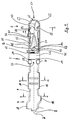
- the plug contact element 1 according to the invention has one designed as a fork spring basic contact 3 and a sleeve-like around the base contact 3 arranged box spring 50 on.
- the basic contact 3 has a rear along a longitudinal axis 2 Connection area 4, a central base area 5 and one Contact area 6, which are integrally connected one behind the other are, the direction of insertion is from front to back.
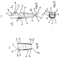
- the connection area 4 is in cross section (Fig. 6, 7) flat, round, circular section with a rounded bottom wall 7 formed, being at its free rear end region 8 each have a crimp flag 10 on an upper edge 9 of the wall 7 is arranged for an electrical conductor.
- the crimp flags 10 are about half of their width with respect to the longitudinal axis 2 arranged offset to each other so that a crimp flag 10 in direct neighborhood to the rear free end 8 is set and the other crimp flag 10 with respect to the longitudinal axis 2 Is shifted forward.
- connection area 3 forward are from the front crimp flag 10 and around whose width is spaced from this, on both upper edges 9 and one crimp flap with respect to the longitudinal axis at the same height 11 arranged for conductor cores of an electrical conductor.
- the Crimp tabs 11 have a width that is approximately three times corresponds to the width of the crimping tabs 10.
- connection area can also be used as an insulation displacement contact or Be solder contact.
- the longitudinal axis 2 to the front includes a Transition piece 15 connected to the base area 5.
- the bottom wall 7 takes a flat Course on, perpendicular to the bottom wall 7 on the longitudinal edges 16 side walls 17 connected extending upwards are so that an open at the top, elongated in cross section U-shaped configuration is achieved.
- the side walls 17 initially widen from the connection area 4 to the base area 5 with a slope 19 to a step 22 in which the side wall 17 has approximately 2/3 of its total width.
- the side walls 17 each have a rectangular shape Recess 18 on, which is opposite at a height are arranged.
- the side walls widen 17 and form guide tabs 20. Adjacent to the guide tabs 20 is in the direction of the longitudinal extension forward, the recesses 18 in the longitudinal direction one each further recess 21 made in the side walls 17.
- the base region 5 Adjacent to the recesses 21 along the longitudinal extent Following in the foreground, the base region 5 has a box shape, being opposite and parallel to the bottom wall 7 a ceiling wall 25 is arranged.
- the top wall 25 is along an upper side edge 26, one of the side walls 17 connected to this.
- the ceiling wall 25 extends to the opposite inside 27 of the other side wall 17, the ceiling wall 25 in the area the upper longitudinal edge 28 of the side wall 17 with your outside 29 ends flush.
- the side walls 17 and the top wall 25 are facing forward end edges 31, 32, 33, 34 formed at a height, with which the base area closes to the front.
- the contact spring arms 37, 38 have a width that is preferably is slightly less than the width of the bottom wall 7 and the top wall 25.
- the contact spring arms 37, 38 extend forward, up to a contact point area or converge to a contact line 40 and their free Ends 41, 42 away from the contact point or from the contact line 40 are bent outwards and form a finding funnel 45.
- the contact line 40 is different from the transverse center 42 of the Base area 5 shifted up to the ceiling wall 25, so that the lower contact spring arms 37 are bent more inward is as the upper contact spring arm 38.
- the bottom wall 7 and top wall 25 Adjacent to the connection area of the contact spring arms 37, 38 the bottom wall 7 and top wall 25 have the contact spring arms 37, 38 on their longitudinal edges 39 pointing outwards or projecting circular segment-shaped tab 44, which after protrude outside.
- the box spring 50 is elongated box or rectangular with a substantially square cross-section, a front Plug opening 51 and a rear opening 52 formed.
- the Box spring 50 has a bottom wall 53, two side walls 54, 55 and a top wall 56 and four longitudinal edges 57 on.
- the bottom wall 53 faces from the longitudinal center Plug-in opening 51 has a U-shaped cutout 59, which extends laterally beyond the side edges 57. This will a spring arm 60, which is towards the plug opening 51 extends cut free.
- the insertion opening 51 has a smaller square cross section Diameter than the box spring 50.
- the plug-in opening 51 are sloping towards one another towards the front Walls 63 arranged, whereby the bottom, side and Converge ceiling walls to the plug opening 51.
- the after forward-facing free ends of the walls 63 are opposite to the Plug direction slightly bent outwards so that a finding funnel 65 is formed. Cover in the direction of insertion the sloping walls 63 the free ends 41, 42 of the contact spring arms 37, 38, so that incorrect insertion is avoided.
- the top wall 56 is on the right side wall in the direction of insertion 54 (Fig.10) tied and extends along the edge 57 parallel to the opposite side wall 55 to the bottom wall 53.
- the polarizing plate 70 has approximately a width that 1/4 to 1/3 of the side walls 54, 55 corresponds.
- a U-shaped cut 71 one pointing backwards and widening a little backwards and cut-up detent spring arm 72 cut free (Fig.4; Fig.10), the free cut 71 over the common edge 57 of the top wall 56 and the side wall 55 extends and on the opposite side over the common edge 57 with the polarizing plate 70 Piece extends upward, the detent spring arm 72 preferably ends with the top edge of the polarizing plate 70 or protrudes beyond it.
- the detent spring arm 72 has a V-shaped configuration 81, the open side to its free rearward end 82 points. At a rear free transverse edge 83 of the free end 82, the detent spring arm 72 has an embossing 84 pointing downward on.
- a spring arm connection tab 73 is located from the side wall 54 bent at right angles and extends to the side wall 55, a rear transverse edge 74 of the spring arm connection tab 73 a little bit below the free cut 71 to the rear limiting transverse edge of the ceiling wall 56 is arranged and firmly connected to it by means of a welding spot 75 is.
- the spring arms 60, 77 lie with free ends 78, 79 on the Contact spring arms 37, 38, with the spring arm 77 less is strongly bent inwards than the spring arm 60.
- the spring arm 77 has at its free end 78 to the contact spring arm 38 has a chamfer 80 (FIG. 12) with which it rests on the contact spring arm 38.
- the spring arms 60, 77 lie approximately in the middle of the longitudinal extent on the contact spring arms 37, 38 on this.
- Tab 85 of the top wall 56 which extends over the side wall 55 extends on the side wall 55 and is with this is connected by means of a welding spot 86.
- the contact spring arms, the spring arms, the Latch spring arm and the polarizing plate on the north-south sides are arranged or oriented in a north-south direction, so that the Plug contact element, which on the east-west sides no protruding Elements, but only has side walls, very much can be made narrow.
- the constructive design according to the invention is the first time before, a contact spring arm, a spring arm and a detent spring arm on one (north-south) side of the plug contact element to arrange without this plug contact element in strength loses.
Landscapes
- Connector Housings Or Holding Contact Members (AREA)
- Details Of Connecting Devices For Male And Female Coupling (AREA)
- Coupling Device And Connection With Printed Circuit (AREA)
Applications Claiming Priority (2)
| Application Number | Priority Date | Filing Date | Title |
|---|---|---|---|
| DE29719153U DE29719153U1 (de) | 1997-10-28 | 1997-10-28 | Miniaturisiertes Steckkontaktelement |
| DE29719153U | 1997-10-28 |
Publications (3)
| Publication Number | Publication Date |
|---|---|
| EP0913886A2 true EP0913886A2 (fr) | 1999-05-06 |
| EP0913886A3 EP0913886A3 (fr) | 2001-01-03 |
| EP0913886B1 EP0913886B1 (fr) | 2003-06-11 |
Family
ID=8047858
Family Applications (1)
| Application Number | Title | Priority Date | Filing Date |
|---|---|---|---|
| EP98119462A Expired - Lifetime EP0913886B1 (fr) | 1997-10-28 | 1998-10-15 | Borne femelle miniaturisée |
Country Status (4)
| Country | Link |
|---|---|
| US (1) | US6126495A (fr) |
| EP (1) | EP0913886B1 (fr) |
| DE (2) | DE29719153U1 (fr) |
| ES (1) | ES2201389T3 (fr) |
Cited By (1)
| Publication number | Priority date | Publication date | Assignee | Title |
|---|---|---|---|---|
| DE10034862A1 (de) * | 2000-07-18 | 2002-01-31 | Grote & Hartmann | Elektrisches Kontaktelement |
Families Citing this family (35)
| Publication number | Priority date | Publication date | Assignee | Title |
|---|---|---|---|---|
| DE59807845D1 (de) * | 1997-12-02 | 2003-05-15 | Tyco Electronics Logistics Ag | Kontaktfeder |
| DE19835020C2 (de) | 1998-08-03 | 2001-02-08 | Tyco Electronics Logistics Ag | Buchsenkontakt |
| JP3556879B2 (ja) * | 2000-03-15 | 2004-08-25 | 住友電装株式会社 | コネクタ |
| US6494751B1 (en) * | 2001-07-20 | 2002-12-17 | Delphi Technologies, Inc. | Terminal-side locking electrical header connector |
| DE10143057A1 (de) * | 2001-09-03 | 2003-03-20 | Delphi Tech Inc | Elektrisches Anschlußelement |
| JP2004006132A (ja) * | 2002-05-31 | 2004-01-08 | Sumitomo Wiring Syst Ltd | 端子金具 |
| JP2004158239A (ja) * | 2002-11-05 | 2004-06-03 | Yazaki Corp | 雌端子、及びその雌端子を備えた電気コネクタ |
| DE10335196B3 (de) | 2003-07-30 | 2005-04-07 | Yazaki Europe Ltd., Hemel Hempstead | Kontaktbuchse für einen Flachstecker |
| JP4552781B2 (ja) * | 2005-07-05 | 2010-09-29 | 住友電装株式会社 | 端子金具 |
| WO2007006874A1 (fr) * | 2005-07-06 | 2007-01-18 | Fci | Contact electrique a patte de retention rapportee |
| KR100630759B1 (ko) * | 2005-08-16 | 2006-10-02 | 삼성전자주식회사 | 멀티 채널 - 싱글 앰프 구조를 갖는 액정 표시 장치의 구동방법 |
| US7517235B2 (en) | 2006-12-28 | 2009-04-14 | General Electric Company | Press fit connection for mounting electrical plug-in outlet insulator to a busway aluminum housing |
| DE102010029192B4 (de) * | 2010-05-20 | 2012-04-05 | Tyco Electronics Amp Gmbh | Steckverbinder und Steckmodulsystem |
| US9308636B2 (en) | 2012-02-03 | 2016-04-12 | Milwaukee Electric Tool Corporation | Rotary hammer with vibration dampening |
| US9166322B2 (en) | 2013-02-08 | 2015-10-20 | Lear Corporation | Female electric terminal with gap between terminal beams |
| DE102014011523B4 (de) | 2013-08-01 | 2025-06-26 | Lear Corporation | Elektrische anschlussanordnung |
| US9190756B2 (en) | 2013-08-01 | 2015-11-17 | Lear Corporation | Electrical terminal assembly |
| US9711926B2 (en) | 2013-11-19 | 2017-07-18 | Lear Corporation | Method of forming an interface for an electrical terminal |
| DE102014118688A1 (de) * | 2014-08-21 | 2016-02-25 | Erni Production Gmbh & Co. Kg | Kontaktelement und Steckverbinder |
| DE102014216864B4 (de) * | 2014-08-25 | 2017-05-11 | Robert Bosch Gmbh | Kontaktelement |
| JP6296358B2 (ja) * | 2015-08-19 | 2018-03-20 | 住友電装株式会社 | 雌端子金具 |
| JP2017139213A (ja) * | 2015-11-30 | 2017-08-10 | タイコ エレクトロニクス (シャンハイ) カンパニー リミテッド | 接続ターミナルおよび接続アッセンブリ |
| US9905953B1 (en) | 2016-09-30 | 2018-02-27 | Slobodan Pavlovic | High power spring-actuated electrical connector |
| CN106384901B (zh) * | 2016-11-29 | 2018-09-04 | 河南天海电器有限公司 | 汽车用激光焊接端子 |
| DE102016125764A1 (de) * | 2016-12-28 | 2018-06-28 | Lear Corporation | Zweistückige elektrische clean-body-anschlussbuchse |
| US10511130B2 (en) * | 2017-09-07 | 2019-12-17 | Suyin Electronics (Dongguan) Co., Ltd | Charging connector having a sleeve with slots surrounding a contact piece with corresponding contact arms |
| JP6989715B2 (ja) | 2018-02-26 | 2022-01-05 | ロイヤル プレシジョン プロダクツ,エルエルシー | 高電力用途用のばね作動式電気コネクター |
| CN112930624B (zh) | 2018-06-07 | 2023-10-03 | 皇家精密制品有限责任公司 | 具有内部弹簧部件的电连接器系统 |
| DE112020000424T5 (de) | 2019-01-15 | 2021-09-23 | Royal Precision Products, Llc | Abgeschirmtes elektrisches steckverbindersystem mit innenliegendem federelement |
| CN113508498B (zh) | 2019-01-21 | 2025-03-18 | 皇家精密制品有限责任公司 | 汇流排系统 |
| DE102019211762A1 (de) * | 2019-08-06 | 2021-02-11 | Lear Corporation | Elektrischer clean-body anschluss |
| US11721942B2 (en) | 2019-09-09 | 2023-08-08 | Eaton Intelligent Power Limited | Connector system for a component in a power management system in a motor vehicle |
| DE112020003846T5 (de) | 2019-09-09 | 2022-05-12 | Royal Precision Products Llc | Verbinderaufzeichnungssystem mit lesbaren und aufzeichenbarenkennzeichnungen |
| JP7734183B2 (ja) | 2020-07-29 | 2025-09-04 | イートン インテリジェント パワー リミテッド | インターロックシステムを含むコネクタシステム |
| FI130101B (fi) * | 2022-01-31 | 2023-02-28 | Parkkisaehkoe Oy | Sähköasennusliitin, menetelmä sähköasennusliittimen valmistamiseksi ja sähköasennusliittimen käyttö |
Family Cites Families (16)
| Publication number | Priority date | Publication date | Assignee | Title |
|---|---|---|---|---|
| DE352871C (de) * | 1922-05-06 | Anton Ebert | Getreideputzmaschine (Gerstenentgranner) | |
| US3836947A (en) * | 1973-02-23 | 1974-09-17 | Amp Inc | Electrical contact receptacle with helper spring |
| DE8502106U1 (de) * | 1985-01-26 | 1985-05-02 | Kabelwerke Reinshagen Gmbh, 5600 Wuppertal | Elektrischer Doppelflachfederkontakt |
| DE8508964U1 (de) * | 1985-03-26 | 1986-12-18 | Grote & Hartmann Gmbh & Co Kg, 5600 Wuppertal | Kastenfeder |
| DE3540869A1 (de) * | 1985-11-18 | 1987-05-21 | Grote & Hartmann | Doppelflachfederkontakt mit aussenueberfeder |
| DE8713038U1 (de) * | 1987-09-28 | 1987-11-19 | Amp Deutschland Gmbh, 6070 Langen | Buchsenartiger elektrischer Anschluß |
| GB8728575D0 (en) * | 1987-12-07 | 1988-01-13 | Amp Gmbh | Electrical socket terminal |
| DE8811020U1 (de) * | 1988-08-31 | 1988-10-20 | Grote & Hartmann Gmbh & Co Kg, 5600 Wuppertal | Federarmkontakt mit Außenüberfeder |
| DE8914951U1 (de) * | 1989-12-18 | 1991-04-18 | Grote & Hartmann Gmbh & Co Kg, 5600 Wuppertal | Elektrisches Kontaktelement mit einer Überfeder |
| US5188545A (en) * | 1990-06-05 | 1993-02-23 | Amp Incorporated | Electrical socket terminal |
| DE9106775U1 (de) * | 1991-06-03 | 1991-07-18 | Amp Inc., Harrisburg, Pa. | Elektrischer Steckkontakt |
| DE9211819U1 (de) * | 1992-07-07 | 1993-11-04 | Grote & Hartmann | Elektrisches Kontaktelement |
| FR2717624B1 (fr) * | 1994-03-21 | 1996-04-26 | Cinch Connecteurs Sa | Organe de contact électrique femelle. |
| DE19517353C1 (de) * | 1995-05-11 | 1996-04-04 | Siemens Ag | Kontaktfeder |
| DE19536264C2 (de) * | 1995-09-28 | 2001-10-18 | Tyco Electronics Logistics Ag | Kontaktfeder mit Rasthülse |
| US5938485A (en) * | 1996-09-30 | 1999-08-17 | The Whitaker Corporation | Electrical terminal |
-
1997
- 1997-10-28 DE DE29719153U patent/DE29719153U1/de not_active Expired - Lifetime
-
1998
- 1998-10-15 DE DE59808684T patent/DE59808684D1/de not_active Expired - Lifetime
- 1998-10-15 ES ES98119462T patent/ES2201389T3/es not_active Expired - Lifetime
- 1998-10-15 EP EP98119462A patent/EP0913886B1/fr not_active Expired - Lifetime
- 1998-10-23 US US09/178,459 patent/US6126495A/en not_active Expired - Lifetime
Cited By (2)
| Publication number | Priority date | Publication date | Assignee | Title |
|---|---|---|---|---|
| DE10034862A1 (de) * | 2000-07-18 | 2002-01-31 | Grote & Hartmann | Elektrisches Kontaktelement |
| DE10034862B4 (de) * | 2000-07-18 | 2009-06-25 | Lear Corp., Southfield | Elektrisches Kontaktelement |
Also Published As
| Publication number | Publication date |
|---|---|
| DE29719153U1 (de) | 1999-03-04 |
| US6126495A (en) | 2000-10-03 |
| ES2201389T3 (es) | 2004-03-16 |
| EP0913886B1 (fr) | 2003-06-11 |
| EP0913886A3 (fr) | 2001-01-03 |
| DE59808684D1 (de) | 2003-07-17 |
Similar Documents
| Publication | Publication Date | Title |
|---|---|---|
| EP0913886B1 (fr) | Borne femelle miniaturisée | |
| EP0577927B1 (fr) | Elément de contact électrique | |
| DE2925938C2 (fr) | ||
| DE69228392T2 (de) | Elektrischer Kontakt | |
| DE3817803C2 (fr) | ||
| DE69221539T2 (de) | Elektrischer Kontakt | |
| DE8914951U1 (de) | Elektrisches Kontaktelement mit einer Überfeder | |
| DE4312641C2 (de) | Elektrische Kontakthülse | |
| EP0272200A2 (fr) | Bloc de connexion pour les télécommunications | |
| EP3843221A1 (fr) | Cadre de support pour un connecteur | |
| DE4131470C2 (fr) | ||
| DE3441416C2 (de) | Elektrische Steckverbindung | |
| DE102016102036B4 (de) | Elektrischer Steckkontakt, elektrische Anschlussklemme und Verfahren zur Herstellung eines elektrischen Steckkontakts | |
| DE69013734T2 (de) | Elektrischer Verbinder. | |
| EP0738028B1 (fr) | Fiche plate | |
| DE4310369C2 (de) | Kontaktsatz für einen Steckverbinder | |
| DE4016114A1 (de) | Elektrischer mehrkontakt-verbinder, der eine geringe verbindungs- und trennkraft erfordert | |
| DE4034094C2 (de) | Elektrisches Kontaktelement mit Kontaktfederarmen | |
| DE8704494U1 (de) | Schraubenlose Anschlußklemme | |
| EP3698439B1 (fr) | Pièce de connecteur enfichable | |
| DE3340035C2 (de) | Kontaktelement mit Eindringklemme sowie Steckergehäuse dafür | |
| DE4306795C2 (de) | Kontaktelement | |
| WO2024125704A1 (fr) | Insert de connecteur à fiche pour un connecteur électrique à fiche | |
| DE2710235A1 (de) | Gehaeuse aus elektrisch isolierendem werkstoff fuer eine elektrische anschlussklemme | |
| DE1954997C3 (de) | Elektrische Steckvorrichtung |
Legal Events
| Date | Code | Title | Description |
|---|---|---|---|
| PUAI | Public reference made under article 153(3) epc to a published international application that has entered the european phase |
Free format text: ORIGINAL CODE: 0009012 |
|
| AK | Designated contracting states |
Kind code of ref document: A2 Designated state(s): DE ES FR IT |
|
| AX | Request for extension of the european patent |
Free format text: AL;LT;LV;MK;RO;SI |
|
| PUAL | Search report despatched |
Free format text: ORIGINAL CODE: 0009013 |
|
| AK | Designated contracting states |
Kind code of ref document: A3 Designated state(s): AT BE CH CY DE DK ES FI FR GB GR IE IT LI LU MC NL PT SE |
|
| AX | Request for extension of the european patent |
Free format text: AL;LT;LV;MK;RO;SI |
|
| 17P | Request for examination filed |
Effective date: 20010623 |
|
| AKX | Designation fees paid |
Free format text: DE ES FR IT |
|
| GRAH | Despatch of communication of intention to grant a patent |
Free format text: ORIGINAL CODE: EPIDOS IGRA |
|
| GRAH | Despatch of communication of intention to grant a patent |
Free format text: ORIGINAL CODE: EPIDOS IGRA |
|
| GRAA | (expected) grant |
Free format text: ORIGINAL CODE: 0009210 |
|
| AK | Designated contracting states |
Designated state(s): DE ES FR IT |
|
| REF | Corresponds to: |
Ref document number: 59808684 Country of ref document: DE Date of ref document: 20030717 Kind code of ref document: P |
|
| ET | Fr: translation filed | ||
| REG | Reference to a national code |
Ref country code: ES Ref legal event code: FG2A Ref document number: 2201389 Country of ref document: ES Kind code of ref document: T3 |
|
| PLBE | No opposition filed within time limit |
Free format text: ORIGINAL CODE: 0009261 |
|
| STAA | Information on the status of an ep patent application or granted ep patent |
Free format text: STATUS: NO OPPOSITION FILED WITHIN TIME LIMIT |
|
| 26N | No opposition filed |
Effective date: 20040312 |
|
| PGFP | Annual fee paid to national office [announced via postgrant information from national office to epo] |
Ref country code: FR Payment date: 20041029 Year of fee payment: 7 Ref country code: ES Payment date: 20041029 Year of fee payment: 7 |
|
| PG25 | Lapsed in a contracting state [announced via postgrant information from national office to epo] |
Ref country code: IT Free format text: LAPSE BECAUSE OF NON-PAYMENT OF DUE FEES Effective date: 20051015 |
|
| PG25 | Lapsed in a contracting state [announced via postgrant information from national office to epo] |
Ref country code: ES Free format text: LAPSE BECAUSE OF NON-PAYMENT OF DUE FEES Effective date: 20051017 |
|
| PG25 | Lapsed in a contracting state [announced via postgrant information from national office to epo] |
Ref country code: FR Free format text: LAPSE BECAUSE OF NON-PAYMENT OF DUE FEES Effective date: 20060630 |
|
| REG | Reference to a national code |
Ref country code: FR Ref legal event code: ST Effective date: 20060630 |
|
| REG | Reference to a national code |
Ref country code: ES Ref legal event code: FD2A Effective date: 20051017 |
|
| PGFP | Annual fee paid to national office [announced via postgrant information from national office to epo] |
Ref country code: DE Payment date: 20171027 Year of fee payment: 20 |
|
| REG | Reference to a national code |
Ref country code: DE Ref legal event code: R071 Ref document number: 59808684 Country of ref document: DE |