EP0914956A2 - Tintenpatrone für einen Drucker - Google Patents
Tintenpatrone für einen Drucker Download PDFInfo
- Publication number
- EP0914956A2 EP0914956A2 EP99103201A EP99103201A EP0914956A2 EP 0914956 A2 EP0914956 A2 EP 0914956A2 EP 99103201 A EP99103201 A EP 99103201A EP 99103201 A EP99103201 A EP 99103201A EP 0914956 A2 EP0914956 A2 EP 0914956A2
- Authority
- EP
- European Patent Office
- Prior art keywords
- ink
- ink supply
- ink cartridge
- supply port
- main body
- Prior art date
- Legal status (The legal status is an assumption and is not a legal conclusion. Google has not performed a legal analysis and makes no representation as to the accuracy of the status listed.)
- Granted
Links
Images

Classifications
-
- B—PERFORMING OPERATIONS; TRANSPORTING
- B41—PRINTING; LINING MACHINES; TYPEWRITERS; STAMPS
- B41J—TYPEWRITERS; SELECTIVE PRINTING MECHANISMS, i.e. MECHANISMS PRINTING OTHERWISE THAN FROM A FORME; CORRECTION OF TYPOGRAPHICAL ERRORS
- B41J2/00—Typewriters or selective printing mechanisms characterised by the printing or marking process for which they are designed
- B41J2/005—Typewriters or selective printing mechanisms characterised by the printing or marking process for which they are designed characterised by bringing liquid or particles selectively into contact with a printing material
- B41J2/01—Ink jet
- B41J2/17—Ink jet characterised by ink handling
- B41J2/175—Ink supply systems ; Circuit parts therefor
- B41J2/17503—Ink cartridges
- B41J2/17553—Outer structure
-
- B—PERFORMING OPERATIONS; TRANSPORTING
- B41—PRINTING; LINING MACHINES; TYPEWRITERS; STAMPS
- B41J—TYPEWRITERS; SELECTIVE PRINTING MECHANISMS, i.e. MECHANISMS PRINTING OTHERWISE THAN FROM A FORME; CORRECTION OF TYPOGRAPHICAL ERRORS
- B41J2/00—Typewriters or selective printing mechanisms characterised by the printing or marking process for which they are designed
- B41J2/005—Typewriters or selective printing mechanisms characterised by the printing or marking process for which they are designed characterised by bringing liquid or particles selectively into contact with a printing material
- B41J2/01—Ink jet
- B41J2/17—Ink jet characterised by ink handling
- B41J2/175—Ink supply systems ; Circuit parts therefor
- B41J2/17503—Ink cartridges
- B41J2/17513—Inner structure
-
- B—PERFORMING OPERATIONS; TRANSPORTING
- B41—PRINTING; LINING MACHINES; TYPEWRITERS; STAMPS
- B41J—TYPEWRITERS; SELECTIVE PRINTING MECHANISMS, i.e. MECHANISMS PRINTING OTHERWISE THAN FROM A FORME; CORRECTION OF TYPOGRAPHICAL ERRORS
- B41J2/00—Typewriters or selective printing mechanisms characterised by the printing or marking process for which they are designed
- B41J2/005—Typewriters or selective printing mechanisms characterised by the printing or marking process for which they are designed characterised by bringing liquid or particles selectively into contact with a printing material
- B41J2/01—Ink jet
- B41J2/17—Ink jet characterised by ink handling
- B41J2/175—Ink supply systems ; Circuit parts therefor
- B41J2/17503—Ink cartridges
- B41J2/1752—Mounting within the printer
- B41J2/17523—Ink connection
Definitions
- the present invention relates generally to an ink cartridge for use with an ink-jet type recording apparatus.
- Ink-jet type recording apparatuses use liquid ink to print recording data.
- an ink-jet type recording apparatus employs an ink cartridge that supplies ink contained therein to the recording head.
- the ink cartridge is directly connected to the recording head through the use of an ink supply needle mounted on the recording head.
- Ink is delivered by utilizing a pressure difference between the ink in the recording head and the ink in the ink cartridge, and by capillary forces.
- the ink cartridge is required to have a structure for connecting the ink cartridge to the ink supply needle.
- This structure is disposed either on the lower surface of the ink cartridge or below the ink cartridge itself.
- This arrangement of the connecting structure in turn requires that an appropriate measure be taken to contain leakage of ink from the ink cartridge when the cartridge is connected to the ink supply needle.
- one method of dealing with the leaking of ink which is widely used is to employ a packing having a through-hole and a seal that allows the ink supply needle to be hermetically fitted into this through-hole at the ink supply port of the ink cartridge. With this structure, the ink cartridge can be positioned and retained in contact with the recording head without allowing any ink to leak by inserting the ink supply needle into the through-hole of the packing so as to pierce the seal.
- the ink supply port provided on the ink cartridge must have a minimal diameter. This design further requires a minimal diameter for the through-hole in the packing that is disposed in the ink supply port.
- the ink supply needle is not positioned precisely coaxial with the through-hole in the packing disposed in the ink supply port, or if the ink supply needle is not perfectly perpendicular with respect to the packing disposed in the ink supply port, then the ink supply needle will not be centered upon insertion into the through-hole of the packing. As a result, the ink supply needle will be in contact with only a portion of the packing, whereas the remaining portion of the packing will not come in contact with the ink supply needle. Thus, ink will leak from between the ink supply needle and the packing where the ink supply needle does not contact the packing.
- This problem of leaking ink also arises from inconsistent positioning tolerances among the multiple ink supply needles in a recording head for a color printer using more than one ink supply needle to supply color inks to a recording head from a plurality of color ink tanks.
- the plurality of color ink tanks is provided as a plurality of compartments in a single tank, so that the spacing between the connecting structures of the ink tank compartment and between the respective ink supply needles is fixed, aggravating the tolerance problem.
- An ink tank is provided with a seal which compensates for inconsistent positioning of ink-supply needles, or inconsistent inclines of ink-supply needles and keeps ink from leaking from the ink supply tank while being in use.
- An ink cartridge for use with an ink-jet type recording apparatus compensates for misalignment of the ink supply port and ink supply needle to stop any ink from leaking.
- a novel ink cartridge which is capable of compensating for any displacement of the ink supply needle with respect to the ink supply port at the time the ink supply needle is connected to the ink supply port.
- the needle and port can be connected with out allowing the ink to leak.
- the ink cartridge comprises at least one self-aligning ring operatively coupled to an ink supply port of the ink cartridge on the outlet or recording head side.
- each ink supply port is coupled with an ink supply needle emanating from the recording head through the self aligning ring.
- the self-aligning ring preferably includes: a first annular seal member whose inner diameter is slightly smaller than an outer diameter of the ink supply needle; a second annular seal member whose outer diameter is slightly larger than an inner diameter of the ink supply port; and a thin connecting member for connecting the two seal members.
- An improved ink transfer mechanism is provided for transferring between an ink cartridge and a recording head.
- An improved ink transfer mechanism is capable of compensating for any misalignment of the ink supply needle with respect to the ink supply port during use.
- An improved ink transfer mechanism is provided wherein a self aligning ring permits a hermetic seal between an ink cartridge and a recording head regardless of misalignment of the ink supply needle with respect to the ink supply port during use.
- the invention according to preferred embodiments comprises the features of construction, combination of elements, and arrangement of parts, which will be exemplified in the construction hereinafter set forth.
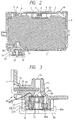
- FIGS. 1 and 2 show an ink cartridge constructed in accordance with a preferred embodiment of the present invention.
- the ink cartridge of this embodiment is especially designed for monochromatic printers.
- an ink cartridge main body indicated generally as 1
- Ink cartridge main body 1 is made of a resin material that suppresses evaporation of ink and is constructed to allow air passage.
- ink cartridge main body 1 The upper opening of ink cartridge main body 1 is covered integrally with a cover 2 having both an ink charging port 3 sealed by a spherical stopper 4 and an air vent 5 similarly sealed by a spherical stopper 6 designed to permit air flow into the ink cartridge while preventing ink loss.
- the air vent 5 communicates with atomosphere through a winding groove 61 and an air communication hole 60.
- An ink supply port, indicated generally as 10, is formed on one side of the bottom of ink cartridge main body 1.
- Ink supply port 10 communicates with an ink supply needle 31 of a recording head (not shown).
- an ink absorbing member 8 formed of a flexible porous material, is disposed within main body 1.
- a biasing plate 7 is positioned with respect to cover 2 to form a gap between cover 2 and ink absorbing member 8.
- the ink supply needle is positioned relative to the ink cartridge by a positioning member 33 which is dimensioned to receive an outwardly projecting portion 12 of the ink receiving and transmitting portion of the ink cartridge which defines the ink supply port.
- Ink supply port 10 includes an inward projecting portion 11 and an outward projecting portion 12.
- Inward projecting portion 11 projects inward into ink cartridge main body 1 to bias ink absorbing member 8.
- Outward projecting portion 12 projects outward from ink cartridge main body 1 to position ink cartridge main body 1.
- Inward projecting portion 11 is preferably provided such as to assist the flow of ink within ink absorbing member 8 to ink supply port 10 by compressing ink absorbing member 8 in the area adjacent inward projecting portion 11 to produce an average pore diameter of ink absorbing member 8 at this location smaller than the average pore diameter of absorbing body 8 at locations not adjacent inward projecting portion 11.
- a stepped insertion hole 14 in outward projecting portion 12 is dimensioned to receive a self-aligning ring 20 (described below).
- a through-hole 16 serving as an ink through-hole (part of the ink supply port) is provided in inward projecting portion 11. Stepped insertion hole 14 and through-hole 16 are formed coaxially so as to communicate with each other when ink cartridge main body 1 is coupled with in supply needle 31 of the recording head.
- Self-aligning ring 20 is made of a flexible resin material and comprises three distinct portions.
- a ring-like annular needle seal 21 (the first seal) having advantageously a circular form in section is coupled with a ring-like annular port seal 22 (the second seal) having advantageously a circular form in section by a thin truncated conical connecting ring 23 that is thinner than annular needle seal 21 or annular port seal 22 in the axial direction.
- the inner diameter of annular needle seal 21 is slightly smaller than the outer diameter of ink supply needle 31.
- the outer diameter of annular port seal 22 is slightly larger than the inner diameter of an entrance portion 14a of stepped insertion hole 14.
- a ring-like movable bush 24 having advantageously an L-shaped form in cross section is fitted adjacent annular needle seal 21 from outside so as to suppress the expansion of needle seal 21.
- the inner diameter of movable bush 24 is substantially smaller than the inner diameter of a portion 14b of stepped insertion hole 14.
- a ring-like fixed bush 25 having advantageously an L-shaped form in section is positioned within annular port seal 22 so as to insure fixed bush 25 remains in contact with the inner surface of entrance portion 14a of stepped insertion hole 14.
- Fixed bush 25 is dimensioned so that the inner end of fixed bush 25 does not come in contact with needle seal 21. Fixed bush 25 guides ink supply needle 31 into stepped insertion hole 14 during insertion.
- Fixed bush 25 is mounted in such a manner that movable bush 24 is in sliding contact with stepped portion 15 within stepped insertion hole 14 and that fixed bush 25 is fitted into entrance portion 14a of insertion hole 14.
- Projections 24a which preferably are radially extending projected bars 24a are formed on the inner end surface 9 of movable bush 24 and are maintained in sliding contact with stepped portion 15 within stepped insertion hole 14.
- ink cartridge main body 1 is evacuated to a negative pressure.
- a plurality of through-holes 24b are formed between projected bars 24a of movable bush 24 so that essentially all of the air within stepped insertion hole 14 can be released from around self-aligning ring 20 through through-holes 24b between the projected bars 24a.
- First seal member 9a in Fig. 2 which can be a sheet of seals the opening end of ink charging port 3, and second seal member 17 in FIG. 1 seals the opening end of ink supply port 10, and is penetrated by ink supply needle 31 during mounting of the ink supply cartridge.
- An electrode 35 extends through a bore 36 in a wall of ink cartridge body 1 and serves as one electrode of an ink exhaustion sensor to inform the user that the ink cartridge requires replacement.
- An O-ring 37 prevents escape of ink through bore 36.
- Ink cartridge main body 1 is coupled with the recording head in such a manner so as to align ink supply port 10 with ink supply needle 31.
- Ink supply needle 31 is inserted into ink supply port 10 while piercing seal member 17 that seals ink supply port 10.
- Ink supply needle 31 then enters into through-hole 16 and is hermetically fitted with movable bush 24.
- ribs 13 disposed around the circumference of the outward projecting portion 12 are fitted into annular positioning projected edge 33a of positioning member 33 disposed on the recording head to thereby fix ink cartridge main body 1 in position.
- Ink cartridge main body 1 is attached to the recording head so as to align ink supply needle 31 with positioning projected edge 33 even if ink supply needle 31 is not projected precisely coaxial with through-hole 16, or if ink supply needle 31 does not project precisely perpendicularly from the recording head.
- ink supply needle 31 is hermetically fitted to needle seal 21 even if not properly situated without greatly deforming needle seal 21. Needle seal 21 moves with movable bush 24 along stepped portion 15 within insertion hole 14 upon insertion of tapered tip portion 32 of ink supply needle 31, and thin conical connecting ring 23 is deformed and displaced in the radial direction outward.
- FIG. 3 depicts the positioning of the movable bush 24 and self-aligning ring 20 when an ink supply needle 31 is not aligned with the axis of insertion hole 14.
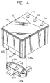
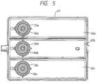
- a cartridge main body 41 has a plurality of ink tanks or compartments 42a, 42b, 42c fixed integrally thereto for containing separate inks, e.g., different color inks.
- Ink supply ports 50a, 50b, 50c having similar self-aligning rings 20a, 20b, 20c are disposed on the bottoms of ink tanks 42a, 42b, 42c.
- Each ink tank 42a, 42b and 42c has an air vent sealed by a stopper 6a, 6b and 6c respectively (FIG. 4).
- the ink changing ports of the three ink tanks or compartments are covered and sealed by sheet member 9'.
- self-aligning rings 20a, 20b, 20c inside the ink supply ports 50a, 50b, 50c are designed so that the misaligned ink supply needles displace the respective needle seals 21 and movable bushes 24 as described above so as to align each needle seal 21 with the position of the corresponding ink supply needle 31a, 31b, 31c while flexing each corresponding thin conical connecting ring 23.
- This construction thereby prevents the ink from leaking, and permits fitting and retaining each ink supply needle 31a, 31b, 31c hermetically with the corresponding needle seal 21 by only deforming the thin connecting members 23.
- an ink cartridge for mounting on at least one ink supply needle 31, 31a, 31b, 31c of a recording head comprises:
- an ink cartridge for mounting on a recording head having at least two ink supply needles 31a, 31b, 31c comprises:
- the ink cartridge main body 1, 41 has a plurality of walls.
- the ink cartridge further includes an annular movable bush 24 having an inner diameter smaller than the outer diameter of said first annular seal member 21 and an outer diameter smaller than the inner diameter of the adjacent region of said ink supply port to limit the expansion of said first annular seal member 21 when the bush 24 is disposed on the outer circumference of said respective first annular seal member 21.
- the annular movable bush 24 has an essentially L-shape in cross section, a first arm of said L being engaged by said outer circumference of said first annular seal member 21, and a second arm of said L being engaged on the interior side of said first annular seal member.
- the respective ink supply port 10, 50a, 50b, 50c is formed with a stepped interior construction defining a region of greater diameter for receiving said self aligning ring 20, 20a, 20b, 20c with the interior side of the second arm of the movable bush 24 facing and engaging said interior step of said ink supply port.
- the interior side of said second arm of said movable bush 24 is formed with spaced projections 24a extending toward and engaging said step.
- the projections 24a are radially extending spaced projections.
- the second arm of said movable bush 24 is formed with at least one through hole providing communication between the interior and exterior of said movable bush.
- the through hole is in a region between said projections.
- the ink cartridge further includes an annular fixed bush 25 for guiding said respective ink supply needle 31, 31a, 31b, 31c disposed along the inner circumference of said second annular seal member 22 to engage said second annular seal member against the inner circumference of the adjacent region of said associated ink supply port 10, 50a, 50b, 50c.
- each of said annular fixed bush 25 has essentially an L-shape in cross-section, a first arm of said L being engaged by said inner circumference of said second annular seal member 22 and a second arm of said L being engaged by the exterior side of said second annular seal member 22.
- the second arm of said respective fixed bush is formed with at least one through hole 25a providing communication between the interior and exterior of said fixed bush.
- the present invention provides a self-aligning ring 20 for receipt within the ink supply port 10 of an ink cartridge.
- the ring 20 includes, on the side thereof facing the interior of the ink cartridge, a first annular seal member 21 whose inner diameter is slightly smaller than the outer diameter of an ink supply needle 31 of a recording head, and on the side thereof facing the exterior of the ink cartridge, the ring includes a second annular seal member 22 whose outer diameter is slightly larger than the inner diameter of the ink supply port 10.
- the seal members 21,22 are connected by a thin flexible connecting member 23.
- the first annular seal member 21 is displaced to conform with the ink supply needle 31 positioned by deforming only the thin connecting member 23 and is hermetically fitted to the ink supply needle 31.
- a self-aligning ring would be mounted in the ink supply port of each compartment for cooperation with an associated ink supply needle.
Landscapes
- Ink Jet (AREA)
Applications Claiming Priority (4)
| Application Number | Priority Date | Filing Date | Title |
|---|---|---|---|
| JP301151/93 | 1993-11-05 | ||
| JP30115193 | 1993-11-05 | ||
| JP30115193A JP3199092B2 (ja) | 1993-11-05 | 1993-11-05 | プリンタ用のインクカートリッジ |
| EP94117447A EP0665108B1 (de) | 1993-11-05 | 1994-11-04 | Tintenpatrone für einen Drucker |
Related Parent Applications (1)
| Application Number | Title | Priority Date | Filing Date |
|---|---|---|---|
| EP94117447A Division EP0665108B1 (de) | 1993-11-05 | 1994-11-04 | Tintenpatrone für einen Drucker |
Publications (3)
| Publication Number | Publication Date |
|---|---|
| EP0914956A2 true EP0914956A2 (de) | 1999-05-12 |
| EP0914956A3 EP0914956A3 (de) | 1999-11-24 |
| EP0914956B1 EP0914956B1 (de) | 2003-02-19 |
Family
ID=17893400
Family Applications (2)
| Application Number | Title | Priority Date | Filing Date |
|---|---|---|---|
| EP99103201A Expired - Lifetime EP0914956B1 (de) | 1993-11-05 | 1994-11-04 | Tintenpatrone für einen Drucker |
| EP94117447A Expired - Lifetime EP0665108B1 (de) | 1993-11-05 | 1994-11-04 | Tintenpatrone für einen Drucker |
Family Applications After (1)
| Application Number | Title | Priority Date | Filing Date |
|---|---|---|---|
| EP94117447A Expired - Lifetime EP0665108B1 (de) | 1993-11-05 | 1994-11-04 | Tintenpatrone für einen Drucker |
Country Status (5)
| Country | Link |
|---|---|
| US (2) | US5633667A (de) |
| EP (2) | EP0914956B1 (de) |
| JP (1) | JP3199092B2 (de) |
| DE (2) | DE69420696T2 (de) |
| SG (1) | SG52541A1 (de) |
Cited By (1)
| Publication number | Priority date | Publication date | Assignee | Title |
|---|---|---|---|---|
| US7195345B2 (en) | 1998-11-11 | 2007-03-27 | Seiko Epson Corporation | Ink-jet printing apparatus and ink cartridge |
Families Citing this family (56)
| Publication number | Priority date | Publication date | Assignee | Title |
|---|---|---|---|---|
| US6145974A (en) * | 1983-10-13 | 2000-11-14 | Seiko Epson Corporation | Ink-supplied printer head and ink container |
| US6474798B1 (en) | 1984-10-11 | 2002-11-05 | Seiko Epson Corporation | Ink supplied printer head and ink container |
| GB2306401B (en) * | 1994-09-16 | 1998-05-06 | Seiko Epson Corp | Ink tank cartridge for a printer or the like |
| JPH08132636A (ja) * | 1994-09-16 | 1996-05-28 | Seiko Epson Corp | インクジェットプリンタ用インクカートリッジ、及びカートリッジへのインクの充填方法 |
| US6238042B1 (en) * | 1994-09-16 | 2001-05-29 | Seiko Epson Corporation | Ink cartridge for ink jet printer and method of charging ink into said cartridge |
| IT1286298B1 (it) | 1995-04-05 | 1998-07-08 | Seiko Epson Corp | Apparecchio di registrazione a getto di inchiostro. |
| GB2323564B (en) * | 1995-05-17 | 1999-02-24 | Dynamic Cassette Int | An ink cartridge for an ink jet printer |
| US5917525A (en) * | 1995-10-30 | 1999-06-29 | Pelikan Produktions Ag | Ink cartridge for a print head of an ink-jet printer |
| US5751322A (en) * | 1996-02-13 | 1998-05-12 | Hewlett-Packard Company | Limited access needle/septum ink-supply interface mechanism |
| DE69733176T2 (de) | 1996-02-21 | 2006-02-16 | Seiko Epson Corp. | Tintenkartusche |
| KR100338451B1 (ko) * | 1996-07-05 | 2002-10-11 | 세이코 엡슨 가부시키가이샤 | 잉크카트리지및잉크카트리지용로딩기구 |
| GB2342619B (en) * | 1996-08-02 | 2000-08-30 | Seiko Epson Corp | Ink cartridge and a printing device using the ink cartridge |
| FR2751916B1 (fr) * | 1996-08-02 | 2000-11-17 | Seiko Epson Corp | Cartouche d'encres et appareil d'impression |
| JP3295339B2 (ja) * | 1996-08-30 | 2002-06-24 | キヤノン株式会社 | インクタンク、ホルダー、インクジェットカートリッジおよびキャップ |
| JPH10193646A (ja) * | 1997-01-09 | 1998-07-28 | Seiko Epson Corp | 印刷ヘッドユニット、これを備えたインクジェットプリンタおよびインクカートリッジ |
| JP3746870B2 (ja) * | 1997-03-07 | 2006-02-15 | セイコーエプソン株式会社 | インクジェット式記録装置用インクカートリッジ |
| JPH10250104A (ja) | 1997-03-12 | 1998-09-22 | Seiko Epson Corp | インクジェット式記録装置用インクカートリッジ、及びその製造方法 |
| US6786420B1 (en) | 1997-07-15 | 2004-09-07 | Silverbrook Research Pty. Ltd. | Data distribution mechanism in the form of ink dots on cards |
| US6618117B2 (en) | 1997-07-12 | 2003-09-09 | Silverbrook Research Pty Ltd | Image sensing apparatus including a microcontroller |
| US7551201B2 (en) | 1997-07-15 | 2009-06-23 | Silverbrook Research Pty Ltd | Image capture and processing device for a print on demand digital camera system |
| US6879341B1 (en) | 1997-07-15 | 2005-04-12 | Silverbrook Research Pty Ltd | Digital camera system containing a VLIW vector processor |
| US6690419B1 (en) | 1997-07-15 | 2004-02-10 | Silverbrook Research Pty Ltd | Utilising eye detection methods for image processing in a digital image camera |
| US7110024B1 (en) | 1997-07-15 | 2006-09-19 | Silverbrook Research Pty Ltd | Digital camera system having motion deblurring means |
| US6624848B1 (en) | 1997-07-15 | 2003-09-23 | Silverbrook Research Pty Ltd | Cascading image modification using multiple digital cameras incorporating image processing |
| US6508546B2 (en) * | 1998-10-16 | 2003-01-21 | Silverbrook Research Pty Ltd | Ink supply arrangement for a portable ink jet printer |
| EP0949080A3 (de) * | 1998-04-06 | 2000-01-26 | Xerox Corporation | Tintenbehälter mit verbesserter Auslassöffnungsdichtung |
| US6299296B2 (en) * | 1998-07-31 | 2001-10-09 | Hewlett Packard Company | Sealing member for a fluid container |
| AUPP702098A0 (en) | 1998-11-09 | 1998-12-03 | Silverbrook Research Pty Ltd | Image creation method and apparatus (ART73) |
| US6805435B2 (en) * | 1998-10-16 | 2004-10-19 | Silverbrook Research Pty Ltd | Printhead assembly with an ink distribution arrangement |
| AUPP701798A0 (en) * | 1998-11-09 | 1998-12-03 | Silverbrook Research Pty Ltd | Image creation method and apparatus (ART75) |
| AUPP702198A0 (en) * | 1998-11-09 | 1998-12-03 | Silverbrook Research Pty Ltd | Image creation method and apparatus (ART79) |
| AUPQ056099A0 (en) | 1999-05-25 | 1999-06-17 | Silverbrook Research Pty Ltd | A method and apparatus (pprint01) |
| JP3755344B2 (ja) * | 1999-07-07 | 2006-03-15 | セイコーエプソン株式会社 | 印刷ヘッド装置およびこれを備えたインクジェットプリンタ |
| PT1095777E (pt) * | 1999-10-29 | 2006-06-30 | Seiko Epson Corp | Cartucho de tinta para utilizacao num aparelho de gravacao de jacto de tinta |
| GB9925988D0 (en) * | 1999-11-03 | 2000-01-12 | Dynamic Cassette Int | An ink cartridge |
| JP4592174B2 (ja) * | 1999-11-15 | 2010-12-01 | オセ−テクノロジーズ ビーブイ | インクペレットディスペンサを有するインクジェット装置 |
| US6332676B1 (en) | 2000-01-05 | 2001-12-25 | Hewlett-Packard Company | Vent for an ink-jet print cartridge |
| US6935730B2 (en) * | 2000-04-03 | 2005-08-30 | Unicorn Image Products Co. Ltd. Of Zhuhai | One-way valve, valve unit assembly, and ink cartridge using the same |
| US20030107626A1 (en) * | 2000-08-16 | 2003-06-12 | Xiao Qingguo | Ink cartridge having bellows valve, ink filling method and apparatus used thereof |
| JP2002079690A (ja) * | 2000-06-30 | 2002-03-19 | Seiko Epson Corp | 保守用カートリッジ、及びこのカートリッジを使用するインクジェット記録装置 |
| US20050243147A1 (en) * | 2000-10-12 | 2005-11-03 | Unicorn Image Products Co. Ltd. | Ink cartridge having bellows valve, ink filling method and apparatus used thereof |
| DE10100171B4 (de) * | 2001-01-04 | 2005-02-24 | Artech Gmbh Design + Production In Plastic | Durchstechbares Verschlusselement und Tintenbehälter mit durchstechbarem Verschlusselement |
| US6929356B2 (en) * | 2001-03-21 | 2005-08-16 | Canon Kabushiki Kaisha | Container of consumable supplies for a printer and printer utilizing the container |
| JP4193435B2 (ja) * | 2002-07-23 | 2008-12-10 | ブラザー工業株式会社 | インクカートリッジ、および、そのインク充填方法 |
| US6386691B1 (en) * | 2001-06-05 | 2002-05-14 | Win-Yin Liu | Ink cartridge of a printer facilitating second refilling |
| US7431427B2 (en) * | 2002-06-13 | 2008-10-07 | Silverbrook Research Pty Ltd | Ink supply arrangement with improved ink flows |
| AU2002323370A1 (en) | 2002-08-22 | 2004-03-11 | Mvm Products, Llc | Universal inkjet printer device and methods |
| AU2003901513A0 (en) * | 2003-03-28 | 2003-04-17 | Proteome Systems Intellectual Property Pty Ltd | Apparatus for dispensing and printing fluids |
| CN2700105Y (zh) * | 2003-10-14 | 2005-05-18 | 珠海天威飞马打印耗材有限公司 | 可组合式连续供墨容器 |
| ATE333371T1 (de) * | 2003-11-19 | 2006-08-15 | 3T Supplies Ag | Tintenpatrone, tintenpatroneneinheit sowie tintenstrahldruckkopf |
| JP4513337B2 (ja) | 2004-01-23 | 2010-07-28 | セイコーエプソン株式会社 | インクカートリッジ |
| US7591400B2 (en) * | 2005-02-28 | 2009-09-22 | Cristian Penciu | Cartridge for dispenser of particular fluid substances |
| JP2006248159A (ja) | 2005-03-14 | 2006-09-21 | Seiko Epson Corp | インクカートリッジおよびその製造方法 |
| JP4737430B2 (ja) * | 2006-06-22 | 2011-08-03 | セイコーエプソン株式会社 | キャリッジ装置、記録装置、液体噴射装置 |
| CN105793050B (zh) * | 2013-11-29 | 2018-06-05 | 株式会社日立产机系统 | 补给容器和包括该补给容器的喷墨记录装置 |
| CN113601989B (zh) * | 2021-07-27 | 2024-01-19 | 珠海天威飞马打印耗材有限公司 | 加墨装置及其加墨方法 |
Family Cites Families (15)
| Publication number | Priority date | Publication date | Assignee | Title |
|---|---|---|---|---|
| DE2709730C2 (de) * | 1977-03-05 | 1981-12-03 | Olympia Werke Ag, 2940 Wilhelmshaven | Tintenbehälter mit einem flexiblen Beutel |
| US4162501A (en) * | 1977-08-08 | 1979-07-24 | Silonics, Inc. | Ink supply system for an ink jet printer |
| US4156244A (en) * | 1977-09-06 | 1979-05-22 | Bell & Howell Company | Ink jet printer ink cartridge |
| DE2916472A1 (de) * | 1979-04-24 | 1980-11-06 | Olympia Werke Ag | Tintenbehaelter |
| JPS57201682A (en) * | 1981-06-08 | 1982-12-10 | Canon Inc | Ink cassette |
| US4591875A (en) * | 1985-04-12 | 1986-05-27 | Eastman Kodak Company | Ink cartridge and cooperative continuous ink jet printing apparatus |
| US4771295B1 (en) * | 1986-07-01 | 1995-08-01 | Hewlett Packard Co | Thermal ink jet pen body construction having improved ink storage and feed capability |
| JPS63162249A (ja) * | 1986-12-26 | 1988-07-05 | Ricoh Co Ltd | インクジエツトプリンタのインクカ−トリツジ装置 |
| JPS63276554A (ja) * | 1987-05-08 | 1988-11-14 | Ricoh Co Ltd | インクカ−トリッジ装置 |
| US4806032A (en) * | 1987-05-11 | 1989-02-21 | Hewlett-Packard Company | Conical vent containing capillary bore |
| DE69031872T2 (de) * | 1989-09-18 | 1998-04-30 | Canon Kk | Methode zum Füllen einer Tintenpatrone für Tintenstrahlaufzeichnungsgeräte |
| JPH03169563A (ja) * | 1989-11-29 | 1991-07-23 | Mitsubishi Pencil Co Ltd | インクジエツトカートリツジ |
| DE69119179T2 (de) * | 1990-10-03 | 1996-10-17 | Canon Kk | Tintenstrahlaufzeichnungsgerät |
| US5477963A (en) * | 1992-01-28 | 1995-12-26 | Seiko Epson Corporation | Ink-jet recording apparatus and ink tank cartridge therefor |
| JP3229444B2 (ja) * | 1993-07-06 | 2001-11-19 | ブラザー工業株式会社 | インク供給装置及びラッピングインク含浸フォーム |
-
1993
- 1993-11-05 JP JP30115193A patent/JP3199092B2/ja not_active Expired - Fee Related
-
1994
- 1994-11-04 EP EP99103201A patent/EP0914956B1/de not_active Expired - Lifetime
- 1994-11-04 US US08/334,719 patent/US5633667A/en not_active Expired - Fee Related
- 1994-11-04 DE DE69420696T patent/DE69420696T2/de not_active Expired - Fee Related
- 1994-11-04 SG SG1996005769A patent/SG52541A1/en unknown
- 1994-11-04 DE DE69432157T patent/DE69432157T2/de not_active Expired - Fee Related
- 1994-11-04 EP EP94117447A patent/EP0665108B1/de not_active Expired - Lifetime
-
1997
- 1997-05-21 US US08/861,253 patent/US5907341A/en not_active Expired - Fee Related
Cited By (1)
| Publication number | Priority date | Publication date | Assignee | Title |
|---|---|---|---|---|
| US7195345B2 (en) | 1998-11-11 | 2007-03-27 | Seiko Epson Corporation | Ink-jet printing apparatus and ink cartridge |
Also Published As
| Publication number | Publication date |
|---|---|
| EP0914956B1 (de) | 2003-02-19 |
| JP3199092B2 (ja) | 2001-08-13 |
| JPH07125238A (ja) | 1995-05-16 |
| US5633667A (en) | 1997-05-27 |
| SG52541A1 (en) | 1998-09-28 |
| EP0665108A3 (de) | 1996-07-24 |
| DE69420696D1 (de) | 1999-10-21 |
| DE69432157T2 (de) | 2003-12-04 |
| US5907341A (en) | 1999-05-25 |
| EP0665108A2 (de) | 1995-08-02 |
| EP0665108B1 (de) | 1999-09-15 |
| HK1020550A1 (en) | 2000-05-12 |
| EP0914956A3 (de) | 1999-11-24 |
| DE69432157D1 (de) | 2003-03-27 |
| DE69420696T2 (de) | 2000-05-31 |
Similar Documents
| Publication | Publication Date | Title |
|---|---|---|
| EP0914956B1 (de) | Tintenpatrone für einen Drucker | |
| EP1687147B1 (de) | Ventil, Tintenpatrone mit diesem Ventil und Tintenversorgungsverfahren | |
| US5126767A (en) | Ink tank with dual-member sealing closure | |
| EP1792737B1 (de) | Tintenzufuhreinheit | |
| EP1013443B1 (de) | Tintenkassette für einen Tintenstrahldrucker | |
| US4928126A (en) | Ink container with dual-member sealing closure | |
| KR100466151B1 (ko) | 교체가능한잉크저장용기,편축형잉크젯인쇄시스템및교체가능한잉크저장용기삽입방법 | |
| US7300142B1 (en) | Ink cartridge for ink-jet printing apparatus | |
| EP0778148A1 (de) | Kodierungsvorrichtung für Tintenzufuhrbehälter | |
| US6280024B1 (en) | Ink cartridge for printer | |
| JPS634953A (ja) | インク供給装置 | |
| US6145967A (en) | Method and apparatus for configuring a fluid interconnect for an ink-jet printhead | |
| JP2023144615A (ja) | カートリッジ、記録装置、及び、カートリッジを製造する方法 | |
| HK1020550B (en) | Ink cartridge for printer | |
| GB2315462A (en) | Ink cartridge having tapered bore | |
| JPS633958A (ja) | インク供給装置 | |
| EP1594703B1 (de) | Tintenpatrone | |
| EP1592560B1 (de) | Tintenpatrone | |
| HK1034493B (en) | Print head device and ink jet printer including the print head device | |
| HK1034493A1 (en) | Print head device and ink jet printer including the print head device | |
| HK1028972B (en) | Ink cartridge for ink jet printer | |
| HK1093042A (en) | Ink cartridge for ink-jet printer |
Legal Events
| Date | Code | Title | Description |
|---|---|---|---|
| PUAI | Public reference made under article 153(3) epc to a published international application that has entered the european phase |
Free format text: ORIGINAL CODE: 0009012 |
|
| 17P | Request for examination filed |
Effective date: 19990218 |
|
| AC | Divisional application: reference to earlier application |
Ref document number: 665108 Country of ref document: EP |
|
| AK | Designated contracting states |
Kind code of ref document: A2 Designated state(s): CH DE FR GB IT LI NL SE |
|
| PUAL | Search report despatched |
Free format text: ORIGINAL CODE: 0009013 |
|
| AK | Designated contracting states |
Kind code of ref document: A3 Designated state(s): CH DE FR GB IT LI NL SE |
|
| 17Q | First examination report despatched |
Effective date: 20011030 |
|
| GRAH | Despatch of communication of intention to grant a patent |
Free format text: ORIGINAL CODE: EPIDOS IGRA |
|
| GRAH | Despatch of communication of intention to grant a patent |
Free format text: ORIGINAL CODE: EPIDOS IGRA |
|
| GRAA | (expected) grant |
Free format text: ORIGINAL CODE: 0009210 |
|
| AC | Divisional application: reference to earlier application |
Ref document number: 0665108 Country of ref document: EP Kind code of ref document: P |
|
| AK | Designated contracting states |
Designated state(s): CH DE FR GB IT LI NL SE |
|
| REG | Reference to a national code |
Ref country code: GB Ref legal event code: FG4D |
|
| REG | Reference to a national code |
Ref country code: CH Ref legal event code: EP |
|
| REF | Corresponds to: |
Ref document number: 69432157 Country of ref document: DE Date of ref document: 20030327 Kind code of ref document: P |
|
| REG | Reference to a national code |
Ref country code: SE Ref legal event code: TRGR |
|
| REG | Reference to a national code |
Ref country code: CH Ref legal event code: NV Representative=s name: ARNOLD & SIEDSMA AG |
|
| ET | Fr: translation filed | ||
| PLBE | No opposition filed within time limit |
Free format text: ORIGINAL CODE: 0009261 |
|
| STAA | Information on the status of an ep patent application or granted ep patent |
Free format text: STATUS: NO OPPOSITION FILED WITHIN TIME LIMIT |
|
| 26N | No opposition filed |
Effective date: 20031120 |
|
| PGFP | Annual fee paid to national office [announced via postgrant information from national office to epo] |
Ref country code: NL Payment date: 20071115 Year of fee payment: 14 Ref country code: DE Payment date: 20071101 Year of fee payment: 14 |
|
| PGFP | Annual fee paid to national office [announced via postgrant information from national office to epo] |
Ref country code: CH Payment date: 20071029 Year of fee payment: 14 Ref country code: IT Payment date: 20071127 Year of fee payment: 14 |
|
| PGFP | Annual fee paid to national office [announced via postgrant information from national office to epo] |
Ref country code: SE Payment date: 20071106 Year of fee payment: 14 |
|
| PGFP | Annual fee paid to national office [announced via postgrant information from national office to epo] |
Ref country code: GB Payment date: 20071031 Year of fee payment: 14 Ref country code: FR Payment date: 20071108 Year of fee payment: 14 |
|
| REG | Reference to a national code |
Ref country code: CH Ref legal event code: PL |
|
| EUG | Se: european patent has lapsed | ||
| GBPC | Gb: european patent ceased through non-payment of renewal fee |
Effective date: 20081104 |
|
| PG25 | Lapsed in a contracting state [announced via postgrant information from national office to epo] |
Ref country code: NL Free format text: LAPSE BECAUSE OF NON-PAYMENT OF DUE FEES Effective date: 20090601 |
|
| NLV4 | Nl: lapsed or anulled due to non-payment of the annual fee |
Effective date: 20090601 |
|
| PG25 | Lapsed in a contracting state [announced via postgrant information from national office to epo] |
Ref country code: IT Free format text: LAPSE BECAUSE OF NON-PAYMENT OF DUE FEES Effective date: 20081104 |
|
| REG | Reference to a national code |
Ref country code: FR Ref legal event code: ST Effective date: 20090731 |
|
| PG25 | Lapsed in a contracting state [announced via postgrant information from national office to epo] |
Ref country code: LI Free format text: LAPSE BECAUSE OF NON-PAYMENT OF DUE FEES Effective date: 20081130 Ref country code: DE Free format text: LAPSE BECAUSE OF NON-PAYMENT OF DUE FEES Effective date: 20090603 Ref country code: CH Free format text: LAPSE BECAUSE OF NON-PAYMENT OF DUE FEES Effective date: 20081130 |
|
| PG25 | Lapsed in a contracting state [announced via postgrant information from national office to epo] |
Ref country code: GB Free format text: LAPSE BECAUSE OF NON-PAYMENT OF DUE FEES Effective date: 20081104 |
|
| PG25 | Lapsed in a contracting state [announced via postgrant information from national office to epo] |
Ref country code: SE Free format text: LAPSE BECAUSE OF NON-PAYMENT OF DUE FEES Effective date: 20081105 |
|
| PG25 | Lapsed in a contracting state [announced via postgrant information from national office to epo] |
Ref country code: FR Free format text: LAPSE BECAUSE OF NON-PAYMENT OF DUE FEES Effective date: 20081130 |