EP0915003A1 - Fahrzeuglenkung - Google Patents
Fahrzeuglenkung Download PDFInfo
- Publication number
- EP0915003A1 EP0915003A1 EP98811100A EP98811100A EP0915003A1 EP 0915003 A1 EP0915003 A1 EP 0915003A1 EP 98811100 A EP98811100 A EP 98811100A EP 98811100 A EP98811100 A EP 98811100A EP 0915003 A1 EP0915003 A1 EP 0915003A1
- Authority
- EP
- European Patent Office
- Prior art keywords
- rotation
- axis
- steering
- steering gear
- angle
- Prior art date
- Legal status (The legal status is an assumption and is not a legal conclusion. Google has not performed a legal analysis and makes no representation as to the accuracy of the status listed.)
- Granted
Links
- 230000005540 biological transmission Effects 0.000 claims abstract description 21
- 238000006073 displacement reaction Methods 0.000 claims description 3
- 210000002414 leg Anatomy 0.000 description 40
- 230000000750 progressive effect Effects 0.000 description 8
- 238000010276 construction Methods 0.000 description 4
- 230000007935 neutral effect Effects 0.000 description 4
- 238000004519 manufacturing process Methods 0.000 description 3
- 230000008901 benefit Effects 0.000 description 2
- 230000008859 change Effects 0.000 description 2
- 230000008878 coupling Effects 0.000 description 2
- 238000010168 coupling process Methods 0.000 description 2
- 238000005859 coupling reaction Methods 0.000 description 2
- 238000010586 diagram Methods 0.000 description 2
- 230000009467 reduction Effects 0.000 description 2
- 210000000689 upper leg Anatomy 0.000 description 2
- 239000006096 absorbing agent Substances 0.000 description 1
- 239000003795 chemical substances by application Substances 0.000 description 1
- 230000007423 decrease Effects 0.000 description 1
- 230000003247 decreasing effect Effects 0.000 description 1
- 230000001419 dependent effect Effects 0.000 description 1
- 230000007246 mechanism Effects 0.000 description 1
Images


Classifications
-
- B—PERFORMING OPERATIONS; TRANSPORTING
- B62—LAND VEHICLES FOR TRAVELLING OTHERWISE THAN ON RAILS
- B62D—MOTOR VEHICLES; TRAILERS
- B62D3/00—Steering gears
- B62D3/02—Steering gears mechanical
-
- B—PERFORMING OPERATIONS; TRANSPORTING
- B62—LAND VEHICLES FOR TRAVELLING OTHERWISE THAN ON RAILS
- B62D—MOTOR VEHICLES; TRAILERS
- B62D1/00—Steering controls, i.e. means for initiating a change of direction of the vehicle
- B62D1/02—Steering controls, i.e. means for initiating a change of direction of the vehicle vehicle-mounted
- B62D1/16—Steering columns
- B62D1/20—Connecting steering column to steering gear
-
- F—MECHANICAL ENGINEERING; LIGHTING; HEATING; WEAPONS; BLASTING
- F16—ENGINEERING ELEMENTS AND UNITS; GENERAL MEASURES FOR PRODUCING AND MAINTAINING EFFECTIVE FUNCTIONING OF MACHINES OR INSTALLATIONS; THERMAL INSULATION IN GENERAL
- F16D—COUPLINGS FOR TRANSMITTING ROTATION; CLUTCHES; BRAKES
- F16D3/00—Yielding couplings, i.e. with means permitting movement between the connected parts during the drive
- F16D3/16—Universal joints in which flexibility is produced by means of pivots or sliding or rolling connecting parts
- F16D3/26—Hooke's joints or other joints with an equivalent intermediate member to which each coupling part is pivotally or slidably connected
Definitions
- the present invention relates to vehicle steering with a variable transmission ratio and a steering gear for such steering.
- the invention relates to a vehicle steering (device for steering a Vehicle) of the type that allows the gear ratio for the translation between the control movement of a steering actuator and the controlled movement of the vehicle components steered by means of the steering vary, with the variability of the gear ratio essentially due to a steering gear is generated.
- a steering gear of this type includes a drive member and an output member and translates movement of the drive member into one Movement of the output member, the transmission ratio being variable.
- the Drive element of the steering gear is coupled to the steering actuation device, where a possible transmission ratio between the movement of the Steering actuator and that of the drive member essentially is constant.
- the output link of the steering gear is with the steered Vehicle components coupled, where again an existing one Gear ratio between the movement of the output member and that of the steered vehicle components is essentially constant.
- a vehicle is generally any vehicle (Land vehicle, watercraft, aircraft, spacecraft) to understand, though to illustrate both the inventive and the known steering systems and steering gear always the most common example in the form of a Passenger car (car) is used.
- Steering actuator usually consists of a steering wheel and the steered Vehicle components are formed by vehicle wheels.
- Steering control device and steered vehicle components from steering wheel or control rudder, in the case of an aircraft consisting of control stick or side and / or horizontal tail.
- Steering gear drive link - usually in the form of a steering gear input shaft - coupled with a steering wheel.
- the steering gear output member is via a steering linkage coupled with the steered vehicle wheels, mostly the front wheels.
- the Steering linkage usually includes tie rods, steering push rods, steering levers and / or other elements.
- the steering gear comprises a rack and pinion mechanism, wherein the steering gear output member forming rack is connected to the steering linkage.
- a Worm roller steering and / or a ball nut hydraulic steering becomes the steering gear output member formed by a so-called steering roller shaft, on which a Steering column lever is attached, which operates the steering linkage.
- the angular position becomes of the steering wheel with ⁇ and that of the steered wheels with ⁇ . Then it will be a total steering movement of the steering wheel by a vehicle steering Angle of rotation d ⁇ in a rotational movement of the steered wheels by a steering angle d ⁇ implemented.
- the gear ratio is between the rotational movement of the steering wheel and that of the steered wheels the entire steering range from one stop of the steering to the other stop essentially constant, i.e. there is a linear relationship between that Angle of rotation da of the steering wheel and the steering angle d ⁇ of the steered wheels.
- gear ratio d ⁇ / d ⁇ ratio between the angle of rotation d ⁇ des Steering wheel and steering angle d ⁇ of the steered wheels
- gear ratio d ⁇ / d ⁇ ratio between the angle of rotation d ⁇ des Steering wheel and steering angle d ⁇ of the steered wheels
- a degressive steering i.e. a steering with a degressive characteristic of the gear ratio
- the gear ratio d ⁇ / d ⁇ ratio between the angle of rotation d ⁇ of the steering wheel and the steering angle d ⁇ of the steered wheels
- Vehicle steering with variable transmission ratio is e.g. by the company "ZF Friedrichshafen AG” from Germany in the form of a rack and pinion steering degressive or progressive characteristics offered.
- the degressiveness or the Progressiveness of this steering is based on a rack, the toothing with different module and pressure angle is made.
- the difference between the The largest and the smallest translation of the rack is approximately maximum 30%.
- From EP 0 737 612 A is a control gear for controlling a Control valve described, which in turn one or more hydraulic cylinders controls for steering an articulated vehicle.
- the control gear includes one Telescopic shaft, at the two longitudinal ends of a universal joint arranged in such a way is that the gimbal errors of the two universal joints do not cancel each other out, but rather reinforce.
- a control gear of this type is suitable because of the two Cardan joints sum up game badly as the actual steering gear since it cannot be set without play.
- steering gears with a variable transmission ratio are known which the variability of the gear ratio by using elliptical Gears is realized.
- the object of the present invention is a steering system with a variable transmission ratio To provide that essentially free of play over the entire steering range is adjustable, has a simple construction and achieves one for Suitable steering ratio enables vehicle steering.
- vehicle steering has a variable transmission ratio a steering gear, which has a drive member rotatable about a first axis of rotation, which via an intermediate member with a rotatable about a second axis of rotation Output member is coupled, the drive member about a third axis of rotation pivotable on the intermediate member and this pivotable about a fourth axis of rotation Output member is articulated.
- the drive link, the intermediate link, the output link and the four axes of rotation are arranged such that the four axes of rotation are in intersect a single point and that between the first axis of rotation and the fourth rotation axis included minimum angles in a range of 0.1 degrees to 40 degrees.
- a steering gear according to the invention for vehicle steering with a variable transmission ratio has a drive member rotatable about a first axis of rotation, which via an intermediate link is coupled to an output link rotatable about a second axis of rotation is, the drive member pivotable about a third axis of rotation on the intermediate member and this is pivoted about a fourth axis of rotation on the output member is.
- the drive link, the intermediate link, the output link and the four Axes of rotation are to be arranged in such a way that the four axes of rotation are in one Intersect point and that between the first axis of rotation and the fourth axis of rotation included minimum angles are in a range of 0.1 degrees to 40 degrees.
- the transmission ratio varies between the rotational movement of the drive member and the associated one Rotary movement of the output link (similar to a universal joint) in operation the angular position of the drive member.
- the gear ratio is in essentially by the angular position of the transmission and by the between the first The axis of rotation and the fourth axis of rotation included which angle itself varies in function of the angular position of the gearbox.
- the arrangement is preferably such that this angle is between 30 degrees and 0.1 degrees. In particular, an arrangement is preferred in which this angle is about 5 degrees. This makes it a compared to previously known Steering gear allows much smaller minimum gear ratio, so that on the arrangement of an additional reduction gear for a Vehicle steering can be dispensed with.
- the steering gear according to the invention essentially consists only of the three Share drive link, intermediate link and output link as well as from first joint means for pivotable articulation of the drive member on the intermediate member and from the second Articulation means for the pivotable articulation of the intermediate link on the output link.
- the steering gear according to the invention thus has an extremely simple construction on. All articulation means required for the steering gear according to the invention adjustable bearings, e.g. Tapered roller bearings, so that the inventive Steering gear adjustable essentially free of play over the entire steering range is.
- these are Drive member and the driven member arranged with respect to each other such that the between the first axis of rotation and the second axis of rotation included in is in a range between 50 degrees and 89.9 degrees.
- the arrangement is preferred such that this angle is between 60 degrees and 89.9 degrees. In particular an arrangement is preferred in which this angle is approximately 70 degrees.
- a further preferred embodiment of the steering according to the invention comprises to operate the steering a steering wheel, which to limit the rotational movement the steering wheel is provided with angle of rotation limiting means.
- the angle of rotation limiting means can e.g. comprise a cam fixedly attached to the steering wheel, which with a cam stop attached to the steering wheel bracket for limitation the rotation to the right and to the left interacts.
- This embodiment the invention proves particularly when used in a Power steering (power steering) as advantageous.
- the maximum steering angle by the stop of the steered wheels limited typically a hydraulic rotary valve to control the Servo drive through the transmission input shaft arranged on the steering wheel on the steering gear controlled. This creates the risk of overloading the hydraulic device the power steering, e.g.
- Another preferred embodiment of the steering gear according to the invention is characterized in that the intermediate member with respect to the output member is arranged that the fourth axis of rotation with respect to the second axis of rotation Angles in the range of 25 degrees to 85 degrees, preferably one between 70 degrees and 80 degrees. In particular, an arrangement is preferred such that this angle is about 75 degrees.
- this embodiment of the steering gear according to the invention there is a range of angular positions (phases) of the transmission, in which a rotary movement of the drive member by a semicircular angle (with the phase as the center) with a rotary movement of the output member is coupled by an angle that is smaller than a semicircle angle. This area is used as the long phase area of the drive element or the short phase area of the output element Are defined.
- a steering gear according to the invention preferably comprises those described above Type means for optional adjustment of the between the fourth axis of rotation and the second axis of rotation (included angle.
- the drive member arranged with respect to the intermediate member such that the first axis of rotation with respect the third axis of rotation includes an angle in the range of 45 degrees to 90 degrees. This angle is preferably approximately 90 degrees.
- the drive member preferably comprises a fork-shaped section (with a similar shape like a bicycle fork) with two fork legs (fork blades), the two fork legs each with the first joint means for pivoting the fork legs on Intermediate link are provided.
- the first articulation means can include journals, which can be screwed into the fork legs and with the corresponding intermediate piece arranged bushings and tapered roller bearings interact. With the screwable spindle, the play of the tapered roller bearings can be adjusted.
- the fork legs can be slotted in the longitudinal direction of the bar and with a Be provided across the slot through hole, in which a Fixing screw can be screwed in, with which the axle journals can be fixed.
- pivotable articulation of the intermediate link on the output link an axle fixed on one side on one of the two parts of a pair of parts, consisting of the intermediate link and the output member, and the other of the two parts of this Pair of parts rotatably supported on the journal by means of bearings.
- the axle journal is fixedly arranged on one side on the output member and the intermediate link is mounted on the journal, or the journal is fixed on one side arranged on the intermediate link and the output member mounted on the journal.
- the Axle journal therefore forms second articulation means in connection with the bearing means the fourth axis of rotation pivotable connection between the intermediate member and the Output link.
- the fourth axis of rotation is through the center of the Axis defined.
- An advantage of the one-sided fastening of the axle journal is the great freedom of movement of the steering gear: for example, this requires that opposite free (flying) end fixed to the output member end the axle pin does not have any carrier and / or support means attached to the intermediate link, which could hinder the movement of the steering gear, in contrast e.g. to a construction like a conventional universal joint.
- the axle journal preferably has a conical section, comprising the Bearing means one or more tapered roller bearings and is the one on the journal Part can be locked in its axial position by means of axially displaceable holding means, by means of axial displacement of the retaining means, the play of the bearing means (and thus the second joint means) is adjustable.
- the holding means can be one with an internally threaded face nut, which on the with a External thread provided free end of the journal can be screwed on to the to fix the part mounted on the journal in its axial position.
- the output member preferably has a first leg section, a second leg section and a web portion connecting the two thighs, the Axle journal is firmly arranged on one side on the web section and the two leg parts each with third articulation means for mounting rotatable about the second axis of rotation of the output member are provided.
- These third joint means can be fixed to the output member attached axle journals to interact with bushings, e.g. are attached to a carrier linkage of a vehicle.
- the output member e.g. also be angular, with a first leg section and a second leg section arranged at an angle to it.
- a journal can be pivoted Articulation of the intermediate link on the output link fixed on one side on the first leg section be arranged and the second leg part with joint means for the second axis of rotation rotatable mounting of the output member.
- Another variant of the steering system according to the invention is characterized in that that the angle set between the first axis of rotation and the second axis of rotation is variably adjustable by the arrangement of the drive member with respect to Arrangement of the output member can be varied. This can change the function according to which the gear ratio as a function of the angle of rotation of the drive member varies. It is preferably between the first axis of rotation and the second axis of rotation set the angle continuously. Thereby the progressivity of the steering can be adjusted.
- this angle is a function of the driving speed adjustable to a speed-dependent progressivity of the steering to reach.
- the fourth axis of rotation closes with respect to the second axis of rotation an angle deviating from 90 degrees, and that between the first rotation axis and the second rotation axis set angle is variable adjustable.
- the angle between the first Axis of rotation and the second axis of rotation are set to a first value at which always has a rotational movement of the drive member with a rotational movement in the same direction of the output member, and to a second value, in which in a certain range of angular positions of the drive member a rotary movement of the drive member with an opposite rotational movement of the output member is coupled.
- This variant of the invention can e.g.
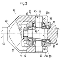
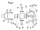
- Fig. 1 is an embodiment of a steering gear 10 of a steering system according to the Invention shown in a side view. 2, the steering gear 10 is in a cross section along the bent line B - B (i.e. through the first axis of rotation 50 and the fourth axis of rotation 56), and FIG. 3 shows an exploded drawing the steering gear 10.
- the steering gear 10 shown in Figures 1 to 3 has a first Rotation axis 50 rotatable drive member 20, which with an intermediate member 30 an output member 40 rotatable about a second axis of rotation 52 is coupled.
- the Drive member 20 is pivotable about a third axis of rotation 54 on the intermediate member 30 articulated.
- the intermediate member 30 is in turn about a fourth axis of rotation 56 hinged to the output member 40.
- the drive member 20 has a fork-shaped portion, which is similar to a bicycle fork has two fork legs (fork blades) 21, 22.
- the two fork legs 21, 22 have each have a bore 23, 24, which is provided with an internal thread.
- In these Bores 23, 24 are each an axle pin 25, 26 provided with an external thread screwable.
- the axle journals 25, 26 each have an outer, thicker section, the is provided with an external thread in order to match the internal thread of the bores 23, 24 interact, and an inner, slimmer section, which on the inside of the drive member 20 protrude beyond the inside of the fork arms 21, 22.
- the inner ones Batches of the axle journals 25, 26 fit into first tapered roller bearings 27, 28, which in corresponding Bores in the intermediate member 30 are arranged.
- Through the joint arrangement 23, 24, 25, 26, 27, 28 is the drive member 20 via the two fork legs 21, 22 pivoted about the third axis of rotation 54 on the intermediate member 30.
- the play of the tapered roller bearings 27, 28 and thus of the pivotable about the axis of rotation 54 The swivel joint can be adjusted by screwing the axle journals 25, 26.
- the fork legs are used to fix the axle journals 25, 26 in a set position 21, 22 with from the bores 23, 24 to the spar tips Longitudinal slots 23a, 24a and one each arranged across the slot Provide bore 29a, 29b, into each of which a fixing screw can be screwed.
- the output member 40 has a first leg section 41 and a second leg section 42 and a web portion 43 connecting the two leg portions 41, 42. To the two leg portions 41, 42 each have an axle 44, 45 is arranged.
- This Axle journals 44, 45 fit into third tapered roller bearings (not shown) around the output member 40 to be rotatable about the second axis of rotation 52.
- This third tapered roller bearing can interact with bearing bushes, e.g. on a support rod of a vehicle are attached.
- journal 31 is fixed on one side to the web portion 43 of the output member 40 arranged.
- the intermediate member 30 is around the fourth by means of tapered roller bearings 32, 33 Axis of rotation 56 is rotatably supported on the journal 31.
- the only one-sided attachment of the journal 31 on the output member 40 has the advantage that it is a great freedom of movement of the steering gear 10 guaranteed by no carrier or support means at the free (flying) end of the journal 31 the movement of the Steering gear 10 hinder.
- the axle journal 31 has a conical section 34.
- the journal 31 For axial displacement and fixing the tapered roller bearings 23, 33 to the journal 31 mounted intermediate member 30, the journal 31 at its flying end 35th an external thread.
- Face nut 36 can be screwed onto the flying end 35 of the axle journal in order to do this to fix the intermediate member 30 mounted on the journal in its axial position.
- the game of tapered roller bearings 23, 33 and thus the order fourth axis of rotation 56 pivotable swivel joint can be set.
- the drive member 20 is relative to the driven member 40 arranged such that the first axis of rotation 50 with respect to the second axis of rotation 52 includes an angle ⁇ deviating from zero degrees of 70 degrees.
- This will a in function of the angular position ⁇ (angle of rotation of the drive member 20 by the first Axis of rotation 50) varying transmission ratio d ⁇ / d ⁇ (ratio between Angle of rotation d ⁇ of the drive member 20 and angle of rotation d ⁇ of the output member 40) generated, ⁇ the angular position of the output member 40 (angle of rotation of the output member 40 about the second axis of rotation 52).
- an angle ⁇ of 75 degrees is included between the second axis of rotation 52 and the fourth axis of rotation 56.
- the angle ⁇ between the first axis of rotation 50 and the third axis of rotation 54 is 90 degrees, which means that when the steering gear 10 is actuated, the angle included between the first axis of rotation 50 and the fourth axis of rotation 56 has a minimum value v is reached as soon as the fourth axis of rotation 56 lies in the plane spanned by the first axis of rotation 50 and the second axis of rotation 52.
- the transmission ratio d ⁇ / d ⁇ described below also reaches its maximum.
- the steering gear 10 shown in Figures 1 to 3 is such in one Steering according to the invention arranged that between the first axis of rotation 50 and the second axis of rotation 52 included angle ⁇ is approximately 70 degrees.
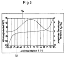
- the kinematics 92 i.e. the dependence of the angular position ⁇ of the output member 40 from the angular position ⁇ of the drive member 20
- the transmission ratio d ⁇ / d ⁇ 94 ratio between the angle of rotation increment d ⁇ of the drive element and Angle of rotation increment d ⁇ of the output member of the steering gear 10 shown shown as diagrams 92, 94 in FIG. 6.
- the stop of the steering gear 10 is both with right and left rotation of the drive member 20 by an angle of rotation d ⁇ of approximately 104 degrees from its zero position.
- the output member 40 is around rotated an angle of rotation d ⁇ of 90 degrees from its zero position.
- the big usable one Angle range from -104 degrees to +104 degrees is a result of the arrangement of the Intermediate member 30 on the output member 40 such that the angle ⁇ between the second axis of rotation 52 and the fourth axis of rotation 56 deviates from 90 degrees.
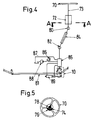
- FIG. 4 shows a preferred embodiment of a steering system according to the invention shown schematically with a device for servo assistance of the steering is provided.
- a steering wheel 70 is rotatably attached to a steering wheel shaft 73 which is rotatable in a steering wheel bracket 72 is mounted.
- the steering is provided with rotation angle limiting means 74.
- the rotation angle limiting means 74 comprise a fixed to the steering wheel shaft 73 attached cam 78, which with a on the steering wheel bracket 72nd attached cam stop 76 cooperates to both the rotational movement of the Steering wheel 70 to the right and to limit that to the left.
- the steering wheel shaft 73 is via universal joints 80, 82, a so-called crash absorber 84 and a hydraulic rotary valve 85 coupled to the steering gear 10, which A steering linkage is actuated via a tie rod 81 to control the steerable wheels To steer the vehicle.
- a servo device is operated via the hydraulic rotary valve 85 controlled, which is essentially a pressure relief valve 86, a hydraulic tank 87, includes a hydraulic pump 88 and a power cylinder 89.
- the hydraulic rotary valve 85 is arranged on the drive side on the steering gear 10 and the working cylinder 89 is arranged on the output side of the steering gear 10.
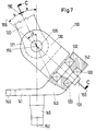
- FIG. 7 is a steering gear 110 according to a second preferred embodiment the invention in a simplified, partially sectioned side view analogous to the Representation shown in Fig. 1.
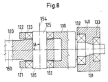
- 8 is the steering gear 110 shown in FIG. 7 in a cross section along the kinked line C - C (i.e. through the first Axis of rotation 150 and the fourth axis of rotation 156) analogous to the illustration in FIG Fig. 2 shown.
- the steering gear 110 shown in Figures 7 and 8 represents one structurally particularly simple and compact embodiment of a Steering gear according to the invention.
- the steering gear 110 shown in Figures 7 and 8 has a first Rotation axis 150 rotatable drive member 120, which with an intermediate member 130 an output member 140 rotatable about a second axis of rotation 152 is coupled.
- the Drive member 120 is pivotable about a third axis of rotation 154 on intermediate member 130 articulated.
- the intermediate member 130 is in turn about a fourth axis of rotation 156 hinged to the output member 140.
- the hinge-side end of the elongate drive member 120 has two flat ones Outside sides, of which one journal 125, 126 protrudes.
- the joint side The end of the elongated drive member 120 is between two plate-shaped extensions 121, 122 of the intermediate piece 130 arranged.
- the journals 125, 126 are in matching bearings 132, 133 added, which in corresponding holes in the plate-shaped extensions 121, 122 of the intermediate piece 130 are arranged to the drive member 120 is pivotable about the third axis of rotation 154 on the intermediate member 130 to steer.
- Intermediate piece 130 At its end opposite the plate-shaped extensions 121, 122 that is Intermediate piece 130 is provided with a protruding journal 131, which is in bearings 132, 133, which are arranged in corresponding bearing bushes on the output member 140, is recorded. As a result, the intermediate member 130 is about the fourth axis of rotation 156 hinged to the output member 140.
- the output member 140 is angular and has a first leg portion 141 and a second leg portion 143.
- the second leg section 143 are the Above-mentioned bearing bushes and bearings 132, 133 arranged with the Axle pin 131 of the intermediate member 130 cooperate.
- On the first Leg portion 141 of the output member 140 an axle pin 145 is arranged.
- This Axle journal 145 fits into bearings (not shown) around the output member 140 second axis of rotation 152 to be rotatably supported, these bearings in corresponding Bearing bushes can be attached to the chassis of a vehicle, which means of the steering gear 110 is steered.
- the first leg portion 141 has one of the Connection angle with the second leg portion 143 via the second axis of rotation 152 extending extension 146, which for actuating the steering linkage of the the steering gear 110 comprehensive steering is used.
- the drive member 120 is relative to the output member 140 arranged such that the first axis of rotation 150 with respect to the second Axis of rotation 152 includes an angle ⁇ of approximately 30 degrees. Between the second The axis of rotation 152 and the fourth axis of rotation 156 is an angle ⁇ of approximately 60 degrees locked in. The angle ⁇ between the first axis of rotation 150 and the third The axis of rotation 154 is 90 degrees. So for the one between the first Rotation axis 150 and the fourth rotation axis 156 included a minimum angle Value ⁇ of approximately 30 degrees.
- Steering gear 210 is characterized by an optionally adjustable angle ⁇ between the second axis of rotation 252 and the fourth axis of rotation 256 and thus an optional adjustable gear ratio.
- the steering gear 210 shown in FIG. 9 has - similar to that in FIG. 1 to 3 shown steering gear 10 - a rotatable about a first axis of rotation 250
- Drive member 220 which has an intermediate member 230 with a about a second axis of rotation 252 rotatable output member 240 is coupled.
- the drive member 220 is around a third axis of rotation 254 pivotally articulated on the intermediate member 230.
- the Intermediate member 230 in turn is pivotable about a fourth axis of rotation 256 Output link 240 articulated.
- the articulated end of the elongated drive member 220 is with two fork legs Mistake.
- the two fork legs are each provided with a hole and bearings, in which two journals 226 essentially between the two fork legs arranged intermediate member 230 are added to the drive member 220 about the third axis of rotation 254 pivotable on the intermediate member 230.
- the output member 240 has a first leg portion 241, a second leg portion 242 and one connecting the two leg parts 241, 242. in the side view 9 essentially semicircular web portion 243.
- On the two Leg portions 241, 242 each have a journal 244, 245 arranged.
- This Axle journals 244, 245 fit in bearings 246, 247 around the output member 240 second axis of rotation 252 to be rotatably supported, these bearings 246, 247 in corresponding bearing bushes on the chassis of a vehicle can, which is steered by means of the steering gear 210.
- the first The leg portion 241 has one of the web portion 143 over the second axis of rotation 252 extending extension 246, which for actuating the steering linkage of the the steering gear 210 comprehensive steering is used.
- the web portion 243 is surrounded by an essentially semi-cylindrical wall 243 formed, the wall 243 being arranged so as to pass through the cylinder axis Intersection of the four axes of rotation 250, 252, 254, 256 runs through.
- a circumferential slot is formed in such a way that the plane defined by the arcuate slot is defined by the Intersection of the four axes of rotation 250, 252, 254, 256 runs through. Is in the slot by means of a mounting flange 239 optionally releasable and lockable again Axle journal 231 fastened in such a way that it in turn passes through the intersection of the four Axes of rotation 250, 252, 254, 256 runs through.
- axles 231 which can always be arranged radially, can thus be attached to any Positions along the slot are attached to the cylindrical wall 243.
- the fourth axis of rotation 256 defined by the journal 231 always by the common intersection of the four axes of rotation 250, 252, 254, 256 runs through. This makes the optional setting of the angle ⁇ between the second Axis of rotation 252 and the fourth axis of rotation 256 and thus the Gear ratio of the steering gear 210 allows.
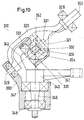
- FIG. 10 is a steering gear 310 according to a fourth preferred embodiment the invention in a simplified, partially sectioned side view analogous to the Representations shown in Figures 1 and 9.
- the one shown in FIG Steering gear 310 is characterized by a storage of the elongated drive member 320 on both sides outside of the intermediate member 330.
- the steering gear 310 shown in FIG. 10 has - similar to that in the figures 1 to 3 shown steering gear 10 - a rotatable about a first axis of rotation 350
- Drive member 320 which has an intermediate member 330 with a about a second axis of rotation 352 rotatable output member 340 is coupled.
- the drive member 320 is around a third axis of rotation 354 is pivotally articulated on the intermediate member 330.
- the Intermediate member 330 is in turn pivotable about a fourth axis of rotation 356 Output link 340 articulated.
- the drive member 320 is arcuate formed, the intermediate member 330 substantially within that of arcuate portion of the drive member 320 is included.
- the drive member 320 is in bearings 328, 329 on both sides of the intermediate link mounted rotatably about the first axis of rotation 350.
- the bearing bushes of bearings 328, 329 are in corresponding bushings on part 390 of the chassis Vehicle attached, which is steered by means of the steering gear 310.
- the arcuate portion of the elongated drive member 320 is two provided tab-shaped projections 321.
- the two tabs 321 are each with one Provided bore and bearings in which two journals 326 of the substantially between the two lobes arranged intermediate member 330 is added are pivotable about the drive member 320 about the third axis of rotation 354 To link intermediate member 330.
- the output member 340 is angular and has a first leg portion 341 and a second leg portion 343. On the second leg portion 343 is a Axle journal 331 formed.
- tapered roller bearings 332, 333 that is with a central intermediate member provided with the journal 331 corresponding bore 330 rotatable about the fourth axis of rotation defined by the journal 331 on the Axle journal 331 mounted.
- An axle journal 345 is located on the first leg portion 341 of the output member 340 arranged. This journal 345 fits in bearings 347, 348 around the output member 340 to rotatably support the second axis of rotation 352, these bearings 347, 348 in corresponding bearing bushes attached to part 390 of the chassis of the vehicle are, which is steered by means of the steering gear 310.
- the first leg section 341 is from the connection angle with the second leg portion 343 over the second
- the axis of rotation 352 also extends to actuate the steering linkage Steering gear 110 comprehensive steering to serve.
- the invention steers the vehicle with variable transmission ratio and a steering gear for such steering be provided, the steering gear essentially consisting solely of a drive member, an intermediate link and an output link consists of joint means for pivotable articulation of the drive member on the intermediate member and the Intermediate link on the output link.
- the steering gear according to the invention thus has an extremely simple construction.
- the steering gear according to the invention essentially over the entire steering range adjustable without play, and it enables the achievement of one for vehicle steering sufficient gear ratio.
Landscapes
- Engineering & Computer Science (AREA)
- Mechanical Engineering (AREA)
- Chemical & Material Sciences (AREA)
- Combustion & Propulsion (AREA)
- Transportation (AREA)
- General Engineering & Computer Science (AREA)
- Power Steering Mechanism (AREA)
Abstract
Description
- Fig. 1
- ein Lenkgetriebe gemäss einer ersten bevorzugten Ausführungsform der Erfindung in einer Seitenansicht;
- Fig. 2
- einen Querschnitt entlang der Linie B - B durch das Lenkgetriebe in Fig. 1;
- Fig. 3
- eine Explosionszeichnung des Lenkgetriebes in Fig. 1;
- Fig. 4
- eine schematische Darstellung einer Servo-Lenkung gemäss einer bevorzugten Ausführungsform der Erfindung;
- Fig. 5
- eine teilweise geschnittene Ansicht entlang der Linie A - A durch die Lenkung in Fig. 5;
- Fig. 6
- eine Diagrammdarstellung der Kinematik und des Übersetzungsverhältnisses des in den Figuren 1 bis 3 dargestellten Lenkgetriebes;
- Fig. 7
- ein Lenkgetriebe gemäss einer zweiten bevorzugten Ausführungsform der Erfindung in einer vereinfachten, teilweise geschnittenen Seitenansicht;
- Fig. 8
- einen Querschnitt entlang der Linie C - C durch das Lenkgetriebe in Fig. 7;
- Fig. 9
- ein Lenkgetriebe gemäss einer dritten bevorzugten Ausführungsform der Erfindung in einer vereinfachten, teilweise geschnittenen Seitenansicht;
- Fig. 10
- ein Lenkgetriebe gemäss einer vierten bevorzugten Ausführungsform der Erfindung in einer vereinfachten, teilweise geschnittenen Seitenansicht.

Claims (10)
- Fahrzeuglenkung mit variablem Übersetzungsverhältnis, mit einem Lenkgetriebe (10; 110; 210; 310), das ein um eine erste Drehachse (50; 150; 250; 350) drehbares Antriebsglied (20; 120; 220; 320) aufweist, welches über ein Zwischenglied (30; 130; 230; 330) mit einem um eine zweite Drehachse (52; 152; 252; 352) drehbaren Abtriebsglied (40; 140; 240; 340) gekuppelt ist, wobei das Antriebsglied (20; 120; 220; 320) um eine dritte Drehachse (54; 154; 254; 354) schwenkbar am Zwischenglied (30; 130; 230; 330) und dieses um eine vierte Drehachse (56; 156; 256; 356) schwenkbar am Abtriebsglied (40; 140; 240; 340) angelenkt ist, gekennzeichnet durch eine Anordnung der vier Drehachsen derart, dass sich die vier Drehachsen in einem einzigen Punkt schneiden und der zwischen der ersten Drehachse (50; 150; 250; 350) und der vierten Drehachse (56; 156; 256; 356) eingeschlossene minimale Winkel (ν) in einem Bereich von 0.1 Grad bis 40 Grad liegt.
- Fahrzeuglenkung nach Anspruch 1, dadurch gekennzeichnet, dass das Antriebsglied (20; 320) bezüglich des Abtriebsgliedes (40; 340) derart angeordnet ist, dass der zwischen der ersten Drehachse (50; 350) und der zweiten Drehachse (52; 352) eingeschlossene Winkel (κ) in einem Bereich zwischen 50 Grad und 89.9 Grad liegt.
- Fahrzeuglenkung nach einem der Ansprüche 1 oder 2, dadurch gekennzeichnet, dass sie zur Betätigung der Lenkung weiter ein Lenkrad (70) umfasst, welches zur Begrenzung der Drehbewegungen des Lenkrades (70) mit Drehwinkel-Begrenzungsmitteln (74, 76, 78) versehen ist.
- Lenkgetriebe (10; 110; 210; 310) für Fahrzeuglenkung nach einem der Ansprüche 1 bis 3, mit einem um eine erste Drehachse (50; 150; 250; 350) drehbaren Antriebsglied (20; 120; 220; 320), welches über ein Zwischenglied (30; 130; 230; 330) mit einem um eine zweite Drehachse (52; 152; 252; 352) drehbaren Abtriebsglied (40; 140; 240; 340) gekuppelt ist, wobei das Antriebsglied (20; 120; 220; 320) um eine dritte Drehachse (54; 154; 254; 354) schwenkbar am Zwischenglied (30; 130; 230; 330) und dieses um eine vierte Drehachse (56; 156: 256; 356) schwenkbar am Abtriebsglied (40; 140; 240; 340) angelenkt ist, dadurch gekennzeichnet dass die vier Drehachsen derart anzuordnen sind, dass sich die vier Drehachsen in einem einzigen Punkt schneiden und der zwischen der ersten Drehachse (50; 150; 250; 350) und der vierten Drehachse (56; 156; 256; 356) eingeschlossene minimale Winkel (ν) in einem Bereich von 0.1 Grad bis 40 Grad liegt.
- Lenkgetriebe (10; 110; 210; 310) nach Anspruch 4, dadurch gekennzeichnet. dass das Zwischenglied (30; 130; 230; 330) bezüglich des Abtriebsgliedes (40; 140; 240; 340) derart angeordnet ist, dass die vierte Drehachse (56; 156; 256; 356) bezüglich der zweiten Drehachse (52; 152; 252; 352) einen Winkel (λ) im Bereich von 25 Grad bis 85 Grad einschliesst.
- Lenkgetriebe (210) nach Anspruch 4 oder 5, gekennzeichnet durch Mittel (239, 243) zur wahlweisen Einstellung des zwischen der vierten Drehachse (256) und der zweiten Drehachse (252) eingeschlossenen Winkels (λ).
- Lenkgetriebe (10) nach einem der Ansprüche 4 bis 6, dadurch gekennzeichnet, dass das Antriebsglied (20) eine gabelförmige Partie mit zwei Gabelholmen (21. 22) umfasst und die beiden Gabelholme (21, 22) je mit ersten Gelenkmitteln (23, 24, 25, 26, 27, 28) zur schwenkbaren Anlenkung der Gabelholme (21, 22) am Zwischenglied (30) versehen sind.
- Lenkgetriebe (10) nach einem der Ansprüche 4 bis 7, dadurch gekennzeichnet, dass zur schwenkbaren Anlenkung des Zwischengliedes (30) am Abtriebsglied (40) ein Achszapfen (31) einseitig fest an einem der beiden Teile eines Teilepaares bestehend aus dem Zwischenglied (30) und dem Abtriebsglied (40) angeordnet ist und das andere der beiden Teile dieses Teilepaares mittels Lagermitteln (32, 33) drehbar auf dem Achszapfen (31) gelagert ist.
- Lenkgetriebe (10) nach Anspruch 8, dadurch gekennzeichnet, dass der Achszapfen (31) einen kegelförmigen Abschnitt (34) aufweist, die Lagermittel (32, 33) ein oder mehrere Kegelrollenlager (32, 33) umfassen und das auf dem Achszapfen (31) gelagerte Teil (30) mittels axial verschieblichen Festhaltemitteln (36) in seiner axialen Position arretierbar ist, wobei mittels axialer Verschiebung der Festhaltemittel (36) das Spiel der Lagermittel (32, 33) einstellbar ist.
- Lenkgetriebe (10) nach Anspruch 8 oder 9, dadurch gekennzeichnet, dass das Abtriebsglied (40) eine erste Schenkelpartie (41), eine zweite Schenkelpartie (42) sowie eine die beiden Schenkelpartien (41, 42) verbindende Stegpartie (43) aufweist, wobei der Achszapfen (31) einseitig fest an der Stegpartie (43) angeordnet ist und die beiden Schenkelpartien (41, 42) je mit dritten Gelenkmitteln (44, 45) zur um die zweite Drehachse (52) drehbaren Lagerung des Abtriebsgliedes (40) versehen sind.
Priority Applications (1)
| Application Number | Priority Date | Filing Date | Title |
|---|---|---|---|
| EP19980811100 EP0915003B1 (de) | 1997-11-07 | 1998-11-03 | Fahrzeuglenkung |
Applications Claiming Priority (3)
| Application Number | Priority Date | Filing Date | Title |
|---|---|---|---|
| EP97810839A EP0915002A1 (de) | 1997-11-07 | 1997-11-07 | Fahrzeuglenkung |
| EP97810839 | 1997-11-07 | ||
| EP19980811100 EP0915003B1 (de) | 1997-11-07 | 1998-11-03 | Fahrzeuglenkung |
Publications (2)
| Publication Number | Publication Date |
|---|---|
| EP0915003A1 true EP0915003A1 (de) | 1999-05-12 |
| EP0915003B1 EP0915003B1 (de) | 2002-02-27 |
Family
ID=26148093
Family Applications (1)
| Application Number | Title | Priority Date | Filing Date |
|---|---|---|---|
| EP19980811100 Expired - Lifetime EP0915003B1 (de) | 1997-11-07 | 1998-11-03 | Fahrzeuglenkung |
Country Status (1)
| Country | Link |
|---|---|
| EP (1) | EP0915003B1 (de) |
Cited By (6)
| Publication number | Priority date | Publication date | Assignee | Title |
|---|---|---|---|---|
| WO2004102039A1 (de) * | 2003-05-15 | 2004-11-25 | Bless Werner M | Progressiver übersetzungsmechanismus |
| EP1637436A1 (de) * | 2004-09-17 | 2006-03-22 | Lorenz Zellweger | Fahrzeuglenkung |
| EP1726507A1 (de) * | 2005-05-27 | 2006-11-29 | ZF Lenksysteme GmbH | Lenkwelle mit Gleichlaufgelenk |
| US7258364B2 (en) * | 2002-06-20 | 2007-08-21 | Werner Bless | Progressive translation mechanism |
| WO2008114161A1 (de) | 2007-03-20 | 2008-09-25 | Endes Management Gmbh | Zahnstangengetriebe |
| WO2024160119A1 (zh) * | 2023-01-30 | 2024-08-08 | 北京车和家汽车科技有限公司 | 角度调节机构、转向系统以及车辆 |
Citations (3)
| Publication number | Priority date | Publication date | Assignee | Title |
|---|---|---|---|---|
| EP0008305A1 (de) | 1978-08-09 | 1980-03-05 | Bayerische Motoren Werke Aktiengesellschaft | Lenkgetriebe mit veränderlichem Übersetzungsverhältnis für Kraftfahrzeuge |
| DE19519588A1 (de) | 1994-05-30 | 1995-12-07 | Honda Motor Co Ltd | Lenkvorrichtung mit variablem Übersetzungsverhältnis |
| EP0737612A2 (de) | 1995-04-10 | 1996-10-16 | Caterpillar Inc. | Lenkung für ein Knickrahmenfahrzeug |
-
1998
- 1998-11-03 EP EP19980811100 patent/EP0915003B1/de not_active Expired - Lifetime
Patent Citations (3)
| Publication number | Priority date | Publication date | Assignee | Title |
|---|---|---|---|---|
| EP0008305A1 (de) | 1978-08-09 | 1980-03-05 | Bayerische Motoren Werke Aktiengesellschaft | Lenkgetriebe mit veränderlichem Übersetzungsverhältnis für Kraftfahrzeuge |
| DE19519588A1 (de) | 1994-05-30 | 1995-12-07 | Honda Motor Co Ltd | Lenkvorrichtung mit variablem Übersetzungsverhältnis |
| EP0737612A2 (de) | 1995-04-10 | 1996-10-16 | Caterpillar Inc. | Lenkung für ein Knickrahmenfahrzeug |
Cited By (8)
| Publication number | Priority date | Publication date | Assignee | Title |
|---|---|---|---|---|
| US7258364B2 (en) * | 2002-06-20 | 2007-08-21 | Werner Bless | Progressive translation mechanism |
| WO2004102039A1 (de) * | 2003-05-15 | 2004-11-25 | Bless Werner M | Progressiver übersetzungsmechanismus |
| EP1637436A1 (de) * | 2004-09-17 | 2006-03-22 | Lorenz Zellweger | Fahrzeuglenkung |
| WO2006029547A1 (de) * | 2004-09-17 | 2006-03-23 | Cygnus Ag | Fahrzeuglenkung |
| EP1726507A1 (de) * | 2005-05-27 | 2006-11-29 | ZF Lenksysteme GmbH | Lenkwelle mit Gleichlaufgelenk |
| WO2008114161A1 (de) | 2007-03-20 | 2008-09-25 | Endes Management Gmbh | Zahnstangengetriebe |
| DE102008014494A1 (de) | 2007-03-20 | 2008-10-16 | Endes Management Gmbh | Zahnstangengetriebe |
| WO2024160119A1 (zh) * | 2023-01-30 | 2024-08-08 | 北京车和家汽车科技有限公司 | 角度调节机构、转向系统以及车辆 |
Also Published As
| Publication number | Publication date |
|---|---|
| EP0915003B1 (de) | 2002-02-27 |
Similar Documents
| Publication | Publication Date | Title |
|---|---|---|
| DE3510536C2 (de) | ||
| EP0915002A1 (de) | Fahrzeuglenkung | |
| DE4403521C2 (de) | Vorrichtung zum Ändern eines Lenkwinkelverhältnisses für ein Fahrzeug | |
| DE2952536C2 (de) | ||
| DE3121196A1 (de) | Lenkeinrichtung fuer fahrzeuge | |
| DE3040144A1 (de) | Einrichtung zur steuerung der fahrgeschwindigkeit und regelung der leerlaufdrehzahl in kraftfahrzeugen mit ottomotor | |
| DE1093224B (de) | Steuerventilbetaetigungsvorrichtung fuer eine hydraulische Hilfskraftlenkeinrichtung | |
| DE4102913C2 (de) | Vorderradlenkeinrichtung | |
| DE3711618C2 (de) | ||
| EP0915003B1 (de) | Fahrzeuglenkung | |
| DE2214001C3 (de) | Servolenkung für Fahrzeuge | |
| DE3600539C2 (de) | ||
| DE3344446A1 (de) | Steuersystem fuer fahrzeuge | |
| DE102013201276B4 (de) | Kardangelenk und damit ausgestattete Lenksäule | |
| DE3820967A1 (de) | Allradlenkeinrichtung fuer kraftfahrzeuge | |
| EP2421741B1 (de) | Fahrzeug-lenksystem der by-wire-bauart | |
| DE3320001A1 (de) | Lenksystem fuer ein fahrzeug mit lenkbaren vorder- und hinterraedern | |
| DE4030625A1 (de) | Servolenkgetriebe | |
| DE3913809C2 (de) | Lenkeinrichtung | |
| DE2104037A1 (de) | Servolenksystem | |
| DE4131785A1 (de) | Lenkvorrichtung fuer die hinterraeder eines kraftfahrzeuges | |
| DE10254687B4 (de) | Hydraulische Servolenkung für Kraftfahrzeuge | |
| DE69201977T2 (de) | Lenksteuereinrichtung für mehrere lenkbare Achsen. | |
| DE3035407C2 (de) | Hilfskraftlenkung für Kraftfahrzeuge | |
| DE2810970C3 (de) | Hydrostatische Hilfskraftlenkeinrichtung für Fahrzeuge |
Legal Events
| Date | Code | Title | Description |
|---|---|---|---|
| PUAI | Public reference made under article 153(3) epc to a published international application that has entered the european phase |
Free format text: ORIGINAL CODE: 0009012 |
|
| AK | Designated contracting states |
Kind code of ref document: A1 Designated state(s): AT CH DE ES FR GB IT LI SE |
|
| AX | Request for extension of the european patent |
Free format text: AL;LT;LV;MK;RO;SI |
|
| 17P | Request for examination filed |
Effective date: 19990712 |
|
| RAP1 | Party data changed (applicant data changed or rights of an application transferred) |
Owner name: WANDFLUH HOLDING AG |
|
| AKX | Designation fees paid |
Free format text: AT CH DE ES FR GB IT LI SE |
|
| RAP1 | Party data changed (applicant data changed or rights of an application transferred) |
Owner name: WANDFLUH AUTOMOTIVE AG |
|
| GRAG | Despatch of communication of intention to grant |
Free format text: ORIGINAL CODE: EPIDOS AGRA |
|
| 17Q | First examination report despatched |
Effective date: 20010523 |
|
| GRAG | Despatch of communication of intention to grant |
Free format text: ORIGINAL CODE: EPIDOS AGRA |
|
| GRAG | Despatch of communication of intention to grant |
Free format text: ORIGINAL CODE: EPIDOS AGRA |
|
| GRAH | Despatch of communication of intention to grant a patent |
Free format text: ORIGINAL CODE: EPIDOS IGRA |
|
| GRAH | Despatch of communication of intention to grant a patent |
Free format text: ORIGINAL CODE: EPIDOS IGRA |
|
| REG | Reference to a national code |
Ref country code: GB Ref legal event code: IF02 |
|
| GRAA | (expected) grant |
Free format text: ORIGINAL CODE: 0009210 |
|
| AK | Designated contracting states |
Kind code of ref document: B1 Designated state(s): AT CH DE ES FR GB IT LI SE |
|
| REF | Corresponds to: |
Ref document number: 213707 Country of ref document: AT Date of ref document: 20020315 Kind code of ref document: T |
|
| REG | Reference to a national code |
Ref country code: CH Ref legal event code: EP |
|
| REG | Reference to a national code |
Ref country code: CH Ref legal event code: NV Representative=s name: KELLER & PARTNER PATENTANWAELTE AG |
|
| REF | Corresponds to: |
Ref document number: 59803181 Country of ref document: DE Date of ref document: 20020404 |
|
| GBT | Gb: translation of ep patent filed (gb section 77(6)(a)/1977) |
Effective date: 20020530 |
|
| ET | Fr: translation filed | ||
| REG | Reference to a national code |
Ref country code: ES Ref legal event code: FG2A Ref document number: 2172111 Country of ref document: ES Kind code of ref document: T3 |
|
| PLBE | No opposition filed within time limit |
Free format text: ORIGINAL CODE: 0009261 |
|
| STAA | Information on the status of an ep patent application or granted ep patent |
Free format text: STATUS: NO OPPOSITION FILED WITHIN TIME LIMIT |
|
| 26N | No opposition filed |
Effective date: 20021128 |
|
| PGFP | Annual fee paid to national office [announced via postgrant information from national office to epo] |
Ref country code: GB Payment date: 20051018 Year of fee payment: 8 |
|
| PGFP | Annual fee paid to national office [announced via postgrant information from national office to epo] |
Ref country code: FR Payment date: 20051028 Year of fee payment: 8 |
|
| PGFP | Annual fee paid to national office [announced via postgrant information from national office to epo] |
Ref country code: SE Payment date: 20051116 Year of fee payment: 8 |
|
| PGFP | Annual fee paid to national office [announced via postgrant information from national office to epo] |
Ref country code: AT Payment date: 20051124 Year of fee payment: 8 |
|
| PGFP | Annual fee paid to national office [announced via postgrant information from national office to epo] |
Ref country code: ES Payment date: 20051125 Year of fee payment: 8 |
|
| PGFP | Annual fee paid to national office [announced via postgrant information from national office to epo] |
Ref country code: DE Payment date: 20051202 Year of fee payment: 8 |
|
| REG | Reference to a national code |
Ref country code: CH Ref legal event code: PUE Owner name: WANDFLUH AG HYDRAULIK + ELEKTRONIK Free format text: WANDFLUH AUTOMOTIVE AG#RECKENTAL#3716 KANDERGRUND (CH) -TRANSFER TO- WANDFLUH AG HYDRAULIK + ELEKTRONIK#HELKENSTRASSE 13#3714 FRUTIGEN (CH) |
|
| PG25 | Lapsed in a contracting state [announced via postgrant information from national office to epo] |
Ref country code: AT Free format text: LAPSE BECAUSE OF NON-PAYMENT OF DUE FEES Effective date: 20061103 |
|
| PG25 | Lapsed in a contracting state [announced via postgrant information from national office to epo] |
Ref country code: SE Free format text: LAPSE BECAUSE OF NON-PAYMENT OF DUE FEES Effective date: 20061104 |
|
| PGFP | Annual fee paid to national office [announced via postgrant information from national office to epo] |
Ref country code: IT Payment date: 20061130 Year of fee payment: 9 |
|
| PG25 | Lapsed in a contracting state [announced via postgrant information from national office to epo] |
Ref country code: DE Free format text: LAPSE BECAUSE OF NON-PAYMENT OF DUE FEES Effective date: 20070601 |
|
| EUG | Se: european patent has lapsed | ||
| GBPC | Gb: european patent ceased through non-payment of renewal fee |
Effective date: 20061103 |
|
| REG | Reference to a national code |
Ref country code: FR Ref legal event code: ST Effective date: 20070731 |
|
| PG25 | Lapsed in a contracting state [announced via postgrant information from national office to epo] |
Ref country code: GB Free format text: LAPSE BECAUSE OF NON-PAYMENT OF DUE FEES Effective date: 20061103 |
|
| REG | Reference to a national code |
Ref country code: ES Ref legal event code: FD2A Effective date: 20061104 |
|
| PG25 | Lapsed in a contracting state [announced via postgrant information from national office to epo] |
Ref country code: FR Free format text: LAPSE BECAUSE OF NON-PAYMENT OF DUE FEES Effective date: 20061130 Ref country code: ES Free format text: LAPSE BECAUSE OF NON-PAYMENT OF DUE FEES Effective date: 20061104 |
|
| PGFP | Annual fee paid to national office [announced via postgrant information from national office to epo] |
Ref country code: CH Payment date: 20081017 Year of fee payment: 11 |
|
| PG25 | Lapsed in a contracting state [announced via postgrant information from national office to epo] |
Ref country code: IT Free format text: LAPSE BECAUSE OF NON-PAYMENT OF DUE FEES Effective date: 20071103 |
|
| REG | Reference to a national code |
Ref country code: CH Ref legal event code: PL |
|
| PG25 | Lapsed in a contracting state [announced via postgrant information from national office to epo] |
Ref country code: LI Free format text: LAPSE BECAUSE OF NON-PAYMENT OF DUE FEES Effective date: 20091130 Ref country code: CH Free format text: LAPSE BECAUSE OF NON-PAYMENT OF DUE FEES Effective date: 20091130 |