EP0915466A2 - Servosektor-Architektur für Wechselmedienplatte mit hoher Speicherdichte - Google Patents
Servosektor-Architektur für Wechselmedienplatte mit hoher Speicherdichte Download PDFInfo
- Publication number
- EP0915466A2 EP0915466A2 EP98650070A EP98650070A EP0915466A2 EP 0915466 A2 EP0915466 A2 EP 0915466A2 EP 98650070 A EP98650070 A EP 98650070A EP 98650070 A EP98650070 A EP 98650070A EP 0915466 A2 EP0915466 A2 EP 0915466A2
- Authority
- EP
- European Patent Office
- Prior art keywords
- disk
- field
- improvement
- servo
- address field
- Prior art date
- Legal status (The legal status is an assumption and is not a legal conclusion. Google has not performed a legal analysis and makes no representation as to the accuracy of the status listed.)
- Withdrawn
Links
Images


Classifications
-
- G—PHYSICS
- G11—INFORMATION STORAGE
- G11B—INFORMATION STORAGE BASED ON RELATIVE MOVEMENT BETWEEN RECORD CARRIER AND TRANSDUCER
- G11B5/00—Recording by magnetisation or demagnetisation of a record carrier; Reproducing by magnetic means; Record carriers therefor
- G11B5/48—Disposition or mounting of heads or head supports relative to record carriers ; arrangements of heads, e.g. for scanning the record carrier to increase the relative speed
- G11B5/58—Disposition or mounting of heads or head supports relative to record carriers ; arrangements of heads, e.g. for scanning the record carrier to increase the relative speed with provision for moving the head for the purpose of maintaining alignment of the head relative to the record carrier during transducing operation, e.g. to compensate for surface irregularities of the latter or for track following
- G11B5/596—Disposition or mounting of heads or head supports relative to record carriers ; arrangements of heads, e.g. for scanning the record carrier to increase the relative speed with provision for moving the head for the purpose of maintaining alignment of the head relative to the record carrier during transducing operation, e.g. to compensate for surface irregularities of the latter or for track following for track following on disks
- G11B5/59633—Servo formatting
- G11B5/59655—Sector, sample or burst servo format
-
- G—PHYSICS
- G11—INFORMATION STORAGE
- G11B—INFORMATION STORAGE BASED ON RELATIVE MOVEMENT BETWEEN RECORD CARRIER AND TRANSDUCER
- G11B27/00—Editing; Indexing; Addressing; Timing or synchronising; Monitoring; Measuring tape travel
- G11B27/10—Indexing; Addressing; Timing or synchronising; Measuring tape travel
- G11B27/19—Indexing; Addressing; Timing or synchronising; Measuring tape travel by using information detectable on the record carrier
- G11B27/28—Indexing; Addressing; Timing or synchronising; Measuring tape travel by using information detectable on the record carrier by using information signals recorded by the same method as the main recording
- G11B27/30—Indexing; Addressing; Timing or synchronising; Measuring tape travel by using information detectable on the record carrier by using information signals recorded by the same method as the main recording on the same track as the main recording
- G11B27/3027—Indexing; Addressing; Timing or synchronising; Measuring tape travel by using information detectable on the record carrier by using information signals recorded by the same method as the main recording on the same track as the main recording used signal is digitally coded
-
- G—PHYSICS
- G11—INFORMATION STORAGE
- G11B—INFORMATION STORAGE BASED ON RELATIVE MOVEMENT BETWEEN RECORD CARRIER AND TRANSDUCER
- G11B20/00—Signal processing not specific to the method of recording or reproducing; Circuits therefor
- G11B20/10—Digital recording or reproducing
- G11B20/12—Formatting, e.g. arrangement of data block or words on the record carriers
- G11B20/1217—Formatting, e.g. arrangement of data block or words on the record carriers on discs
-
- G—PHYSICS
- G11—INFORMATION STORAGE
- G11B—INFORMATION STORAGE BASED ON RELATIVE MOVEMENT BETWEEN RECORD CARRIER AND TRANSDUCER
- G11B20/00—Signal processing not specific to the method of recording or reproducing; Circuits therefor
- G11B20/10—Digital recording or reproducing
- G11B2020/1087—Digital recording or reproducing wherein a selection is made among at least two alternative ways of processing
- G11B2020/10879—Digital recording or reproducing wherein a selection is made among at least two alternative ways of processing the kind of record carrier being the selection criterion
-
- G—PHYSICS
- G11—INFORMATION STORAGE
- G11B—INFORMATION STORAGE BASED ON RELATIVE MOVEMENT BETWEEN RECORD CARRIER AND TRANSDUCER
- G11B2220/00—Record carriers by type
- G11B2220/20—Disc-shaped record carriers
Definitions
- This invention relates generally to removable media-type disks for rotational use in a floppy disk drive and, more particularly, it relates to formatting of servo sector architecture on a high-density, removable media-type disk for rotational use in a floppy disk drive and to the floppy disk itself.
- accurately positioning the heads at the desired position over the disk in a hard disk drive is generally accomplished by formatting certain servo information on one or more of the disk surfaces for use by the magnetic heads in determining the head's positional orientation over the disk.
- stepper motors were used to position the actuator and the head.
- sector-servo also known as embedded servo
- the servo information is interspersed with data on each disk surface.
- the sector servo approach has the advantage of providing the positioning information close to the data sectors the positioning information identifies, thereby eliminating sources of track misregistration which otherwise tend to limit track density.
- a disadvantage of the sector servo format as generally used today is that the sector servo incurs additional overhead storage requirements in order to permit smooth transitions between data regions and servo regions.
- no-ID or headerless format uses servo sectors to identify the data sectors and completely eliminate the use of a data ID region.
- each sector on a track is composed of two regions: a servo region and a data region.
- the servo sectors are located using a servo ID mark or address mark.
- Each data sector is identified with the servo sector's cylinder, head, and sector number counted from an index location. No separate data ID field is required since all address information is in the servo field.
- This format is the same for all sectors on all tracks of the disk.
- ZBR zone bit recording
- a servo sector architecture which effectively combines the ZBR and no-ID formats in a high density, removable media-type disk drive for rotational use in a floppy disk drive, which specific servo sector architecture enables the data recording head to locate and identify data sectors for both read and write operations.
- the present invention is an improvement for a high density, removable media-type disk for rotational use in a floppy disk drive having a read/write head.
- the disk includes one or more servo sectors.
- the improvement comprises certain magnetically written servo information on the disk readable by the read/write head during normal operation of the disk drive, the information includes a constant frequency field, a gap and servo timing mark field, a gray encoded address field, a binary address field, and a position field.
- the improvement comprises the gap and servo timing mark field being positioned downstream from the constant frequency field, the gray encoded address field being positioned downstream from the gap and servo timing mark field, the binary address field being positioned downstream from the gray encoded address field, and the position field being positioned downstream from the binary address field.
- the improvement comprises the information within each of said servo sectors consisting essentially of the constant frequency field, the gap and servo timing mark field being positioned downstream from the constant frequency field, the gray encoded address field being positioned downstream from the gap and servo timing mark field, the address field being positioned downstream from the gray code field, and the position field being positioned downstream from the address field.
- the disk includes a plurality of servo sectors and wherein the servo sectors are equally angularly spaced.
- the disk has between approximately eighty (80) and approximately two hundred (200) servo sectors per track or servo wedges.
- the disk has ninety (90) equally angularly spaced servo sectors.
- the information in the servo sector can be described in terms of clock cells.
- One clock cell can be referenced to a physical location on the disk as a unit of rotational arc.
- the physical length of one clock cell is 2 ⁇ /360,000.
- the gap and servo timing mark field has a first space, a first pulse downstream from the first space, a second space downstream from the first pulse, and a second pulse downstream from the second space.
- the first space has a length of twelve (12) clock cells and the second space has a length of six (6) clock cells. It is to be understood that one angular measurement unit, as used herein, equals 2 ⁇ /360,000.
- the first pulse is a positive pulse and the second pulse is a negative pulse.
- the gray encoded address field has a length of approximately seventy-two (72) clock cells.
- the binary address field has a length of approximately seventy-two (72) clock cells. Furthermore, preferably, the binary address field has sector information, head information, index information, and at least one (1) reserved bit for each servo sector. In a preferred embodiment, the binary address field has one (1) head bit, seven (7) sector bits, one (1) index bit, and at least one (1) reserved bit (where one bit is equal to six encoded clock cells).
- the position field has a length of approximately eighty (80) clock cells. Furthermore, preferably, the position field comprises four (4) position sub-fields within the position field and further comprises a two (2) clock cell space between each of the position sub-fields.
- the disk includes a data section containing data fields and wherein none of the data fields includes identification information thereby providing additional data density on the disk.
- the data field comprises between approximately one (1) and sixteen (16) data zones.
- the data field comprises eight (8) data zones.
- the improvement further comprises eight (8) clock cells between the position field and the data field.
- the improvement also comprises a disk cover or cartridge surrounding the disk.
- the disk and disk cartridge are configured to operate within a high density disk drive with the disk cartridge being sized and shaped to conform to the size and shape of a standard 3.5 inch disk cartridge whereby the size and shape of the standard disk and disk cartridge will not preclude it from being properly operated within the high density drive.
- the present invention is also an improvement to a high density, removable media-type disk for rotational use in a floppy disk drive.
- the disk has at least one servo sector field and at least one data field per track.
- the improvement comprises identification information in the servo sector field with the data field being free from identification information.
- the present invention is further an improvement to a high density, removable media-type disk drive.
- the disk drive has a recording head for writing information on and reading information from the disk.
- the improvement comprises read/write means operating in a high density mode for reading from or writing to a high density disk and alternatively operating in a low density mode for reading from and writing to a low density disk.
- the means for reading from or writing to a high density disk and alternatively for reading from and writing to a low density disk include a rotating mechanism which rotates at a first slower speed when operating in the low density mode and a second faster speed when operating in said high density mode.
- the read/write means include operating the rotating mechanism such that the rotating mechanism rotates at the slower speed first and then increases to the second faster speed.
- the improvement further comprises a spin mechanism for reading the disk in a high density mode and determining whether a low or high density disk is present while the spin mechanism operates at the low density speed. If the disk is a high density disk, the spin mechanism will then rotate the disk at the second faster speed.
- the improvement comprises the first speed being approximately 600 rpm and the second speed being approximately 1000 rpm.
- the present invention further includes a method of operating a disk drive.
- the method comprises the steps of providing a high density, removable media-type disk drive which is configured to receive a high density disk or a low density disk, inserting a low density disk into a predetermined operating position within a receiving chamber of the disk drive and reading information from and/or writing information to the low density disk, and alternatively inserting a high density disk into a predetermined operating position within the same receiving chamber of the disk drive and reading information from and/or writing information to the high density disk.
- the method further includes the step of initially operating the disk drive in a predetermined manner to allow the disk drive to determine whether the disk is a high density disk or a low density disk.
- the present invention is a high density, removable media-type disk for rotational use in a floppy disk drive having a read/write head.
- the disk has at least one servo sector and at least one data field.
- the disk comprises between approximately eighty (80) and approximately two hundred (200) servo sectors or servo wedges per track.
- the servo sectors are equally angularly spaced.
- the disk has ninety (90) servo sectors or servo wedges per track.
- the disk further comprises certain information readable by the read/write head during normal operation of the disk drive.
- the information includes a constant frequency field, a gap and servo timing mark field being positioned downstream from the constant frequency field, a gray encoded address field being positioned downstream from the gap and servo timing mark field, a binary address field being positioned downstream from the gray code field, and a position field being positioned downstream from the address field.
- the present invention is an improvement to a high density, removable media-type disk for rotational use in a floppy disk drive.
- the disk includes one or more servo sectors per track.
- the improvement comprises means on the disk for identifying if the disk is a low density disk or a high density disk.
- the means comprise certain information within the servo sector.
- the present invention is a disk drive system having a floppy disk drive for rotating a high density, removable media-type disk.
- the disk has at least one servo sector and at least one data field per track.
- the system comprises a disk drive having a read/write head, a high density, removable media-type disk operated by the disk drive with the disk containing certain information readable by the read/write head during normal operation of the disk drive.
- the information includes a constant frequency field, a gap and servo timing mark field, a gray encoded address field, a binary address field, and a position field.
- each data field is free from identification information thereby providing additional data density on the disk.
- the position field comprises four (4) position sub-fields within the position field.
- a pad is positioned between each of the position sub-fields.
- a pad is positioned between the position field and the data field.
- the system further comprises a disk cartridge surrounding the disk.
- the disk and disk cartridge are configured to operate within a high density disk drive with the disk cartridge being sized and shaped to conform to the size and shape of the standard 3.5 inch disk cartridge whereby the standard disk and disk cartridge is also receivable within the high density drive.
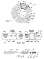
- the present invention is a high density, removable media-type disk, indicated generally at 10, for rotational use in a high density, removable media-type floppy disk drive 12, as illustrated in FIG. 5.
- the disk 10 is formatted using a fixed block architecture with sector servo and zone-bit recording.
- the disk 10 of the present invention allows greater track density derived from the use of a voice coil actuator instead of a stepper motor.
- the disk drive 12 includes the data recording disk 10, a voice coil actuator arm 21, a data recording transducer 17 (also called a recording head), a voice coil motor 23, servo electronics, read/write electronics, interface electronics, formatter electronics, all of which are generally indicated at 9, a microprocessor 19 including RAM.
- the data recording disk 10 includes a center of rotation 14, and is divided for head positioning purposes into a set of radially spaced tracks 15. The tracks are grouped radially into a number of constant frequency regions or zones, six of which are shown as 16, 18, 20, 22, 24, and 26.
- the disk 10 of the present invention contains a plurality of servo wedges or sectors 28 per track, which extend across the tracks 15 in a generally radial direction from the center of rotation 14. It is preferred that the number of servo wedges or sectors 28 per track be maintained at a minimum to maximize the data density capacity of the disk 10.
- the disk 12 includes between approximately eighty (80) and approximately two hundred (200) equally angularly spaced servo sectors or wedges 28 per track although a disk having less than approximately eighty (80) servo wedges or sectors per track and greater than approximately two hundred (200) servo wedges or sectors per track is within the scope of the present invention.
- the tracks 15 are also circumferentially divided into a number of data fields or sectors 30.
- the data fields 30 contain no sector ID fields thereby providing additional data density on the data recording disk 10.
- the identification information needed by the disk drive to correctly position the transducer 17 over the disk 10 is provided entirely within the servo sectors 28 on the data recording disk 10. The actual information and configuration of the servo sectors 28 of the disk 10 of the present invention will be discussed in further detail below.
- the data recording disk 10 of the present invention has a plurality of data zones 16-26 thereby increasing the data storage capacity of the data recording disk 10 as contrasted with a typical low density, single zone floppy disk.
- the disk 10 of the present invention there are as many as sixteen (16) zones 16-26, although a disk 10 having greater than sixteen (16) data zones 16-26 is within the scope of the present invention. Since a small number of zones 16-26 reduces the amount of data storable on the disk 10 and a high number of data zones 16-26 requires more microcode to implement and maintain, the inventors of the present invention have discovered that the optimum number of data zones 16-26 for optimum functionality of the disk drive 12 is actually approximately eight (8) data zones 16-26.
- a constant frequency field 31 assists the read/write electronics in synchronizing stored data in the data sector 30 on the disk 10.
- the length and positioning of the constant frequency field 31 is directly related to the rotational spin speed of the disk 10 and the data rate in the data zones 16-26.
- all data sectors 30 on the data recording disk 10 are substantially the same size, expressed in bytes of data. However, it is within the scope of the present invention to have variation in the data sector size, such as from 128 bytes per data sector 30 to 4098 bytes per data sector 30, in the event that such a configuration is desirable for a particular implementation.
- the number of data sectors 30 per track 15 varies from zone to zone, and some of the data sectors 30 do not begin immediately following a particular servo sector 28. Further, some of the data sectors 30 are split by servo sectors 28, as best illustrated in FIG. 1.
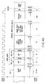
- FIG. 2a a detailed schematic diagram of the servo sector architecture for an exemplary track 15 from a data recording disk 10 in accordance with the present invention is provided.
- a portion of the track 15 is illustrated at 32, containing a servo sector 28 and part of a data sector 30.
- the data sectors 30 are separated from one another by the servo sectors 28.
- a constant frequency field 34 is used to allow the read/write electronics to switch from a data writing operation to a servo reading operation, and to allow for fluctuations in the data recording disk's 10 rotational speed.
- the transducer 17 reads information from the servo sector 28 to locate the correct address for the transducer 17 to read from or write to the disk surface of the data recording disk 10. Basically, the transducer 17 reads the position from the servo sector 28 and the microprocessor 19 instructs the transducer 17 where to go on the data recording disk 10.
- the sector servo 28 of the disk 10 of the present invention comprises certain information readable by the read/write head during normal operation of the disk drive.
- the information includes a constant frequency field 34, a gap and servo timing mark field 36, a gray encoded address field 38, a binary address field 40, and a position field 42.
- the information is in a specific sequentially readable order with the constant frequency field 34 being read first.
- the gap and servo timing mark field 36 is positioned downstream from the constant frequency field 34
- the gray encoded address field 38 is positioned downstream from the gap and servo timing mark field 36
- the binary address field 40 is positioned downstream from the gray encoded address field 38
- the position field 42 is positioned downstream from the binary address field 40.
- the constant frequency field 34 of the sector servo 28 of the disk 10 of the present invention is a signal having a continuous frequency which allows the disk drive 12 to synchronize the read/write signal to the rotational data in order to detect and acquire the gap and servo timing mark 36 of the servo sector 28.
- the final size of the constant frequency field 34 is determined by the read/write electronics within the disk drive. It should be noted that when the sector servos 28 of the disk 10 are initially servo written on the disk 10, the constant frequency field 34 is written between each servo field. As data sectors are written to the disk, the constant frequency field 34 is overwritten except for a portion required by the read/write electronics.
- the gap and servo timing mark 36 of the servo sector 28 of the disk 10 of the present invention allows the disk drive to read the address information necessary to correctly position the transducer 17 over the data recording disk 10 and to determine that the transducer is at the beginning of the servo sector 28.
- the gap and servo timing mark field 36 of the present invention comprises a first space 46, a first pulse 47 downstream from the first space 46, a second space 48 downstream from the first pulse 47, and a second pulse 49 downstream from the second space 48.
- the time between the last constant frequency pulse and the first servo timing mark pulse 47 and the time between the first timing mark pulse 47 and the second pulse 49 is critical for synchronizing the disk drive since the servo control state machine must validate the gap and servo timing mark 36 for a particular data recording disk 10. Both the first space 46 and the second space 48 must be exactly positioned for proper timing determination and should not be repeated in the data sectors 30 to allow for maintaining servo synchronization.
- the servo timing mark 36 precisely identifies a specific position within the servo sector 28 which is used as a timing reference.
- the inventors in the subject application have determined that, preferably, the first space 46 has a length of twelve (12) clock cells and the second space 48 has a length of six (6) clock cells.
- the first pulse 47 is a positive pulse and the second pulse is a negative pulse 49, although it is within the scope of the present invention to switch the negative and positive pulses.
- the gray encoded address field 38 of the servo sector 28 of the disk 10 of the present invention provides a gray encoded address field to the disk drive for correctly positioning the transducer 17 over the correct cylinder on the data recording disk 10.
- the gray encoded address field 38 has a length of approximately seventy-two (72) clock cells.
- the binary address field 40 of the servo sector 28 of the disk 10 of the present invention provides sector information, head information, and index information to the transducer 17 of the disk drive 12 for correctly positioning the transducer over the data recording disk 10 and to determine the rotational position of the disk 10 thereby allowing the data sector 30 to be free from identification information.
- the binary address field 40 has a length of approximately seventy-two (72) clock cells.
- the binary address field 40 has a reserved portion which is used by the manufacturer to specify a particular format for the data recording disk 10.
- the reserved portion allows different products and different formats for different users.
- the reserved portion has at least one (1) reserved bit 56 for each servo sector 28.
- the binary address field 40 has one (1) head bit 50, seven (7) sector bits 52, one (1) index bit 54, and at least three (3) reserved bits 56 (where one (1) bit is equal to six (6) encoded clock cells.
- the position field 42 of the servo sector 28 of the disk 10 of the present invention contains the actual servo information used to position the transducer 17, typically including a quadrature position error signal comprised of four (4) equal sub-fields.
- the position field 42 has a length of approximately eighty (80) clock cells.
- the position field 42 comprises four (4) position sub-fields 58, 60, 62, and 64 within the position field 42 .
- the four position sub-fields 58, 60, 62, and 64 have a two (2) clock cell space between them and are for a position system using quadrature detection.
- the servo sector 28 of the disk 10 of the present invention further comprises a space 68 of eight (8) clock cells positioned downstream from the position field 42.
- the disk 10 of the present invention further comprises a disk cover or cartridge 10a surrounding the data recording disk 10 thereby forming an overall disk assembly 10b.
- the data recording disk 10 and the disk cartridge are configured to operate within a high density disk drive 12 with the disk cartridge being sized and shaped to conform to the size and shape of a standard 3.5 inch disk cartridge 13. In this way, the size and shape of the standard disk and disk cartridge 13 will not preclude it from being properly operated within the high density disk drive 12 of the present invention.
- the disk drive of the present invention comprises a read/write mechanism for reading from and writing to either a high density disk or a low density disk.
- the read/write mechanism includes a rotating mechanism which rotates at a first slower speed when operating in the low density mode and a second faster speed when operating in the high density mode.
- the rotating mechanism comprises a spindle motor and a hub with a chucking mechanism. Since a standard 3.5 inch standard disk has certain specifications which are not appropriate for rotating at faster speeds, it is important to maintain the slower speed for these disks when rotatingly operating within the disk drive.
- the rotating mechanism of the present invention rotates the data recording disk 10 within the disk drive at the first slower speed and then increases to the second faster speed, if the disk drive determines that the disk is a high density disk.
- the first slower speed is approximately six hundred (600) rpm and the second faster speed is approximately one thousand (1000) rpm. It is within the scope of the present invention, however, to have a faster or slower first speed and a faster or slower second speed.
- the disk drive of the present invention further comprises a mechanism for determining whether a low or high density disk is operating within the disk drive.
- the determination mechanism determines whether a low or high density disk is present in the disk drive while the read/write mechanism operates in the low density mode. This is because a high density disk can operate without damage at a low density disk speed but the reverse is not true.
- the determination mechanism forms part of the electronics illustrated in FIG. 5 and generally at 9. It includes an arrangement for attempting to read the servo information on a high density floppy disk (low density disks have no sectored servo data). If there is servo information written, this information can be read safely at the slower speed and then the disk is presumed to be a high density disk, the read/write mechanism operates at the high density mode causing the rotating mechanism to rotate the data recording disk 10 at the second faster speed.
- the disk drive 12 of the present invention preferably includes a carriage assembly which is described in European Patent Application No. corresponding to U.S. Patent Application No. 08/965233 filed concurrently herewith and incorporated herein by reference. Furthermore, preferably, the disk drive 12 of the present invention includes a magnetic recording encoder system for a (1,7) channel having a 2/3 coding rate which is described in European Patent Application No. corresponding to U.S. Patent Application No. 08/965112 filed concurrently herewith and incorporated herein by reference.
- the disk drive of the present invention operates in a high density mode for reading from or writing to a high density disk and alternatively operating in a low density mode for reading from and writing to a low density disk.
- the disk drive of the present invention is able to determine whether the disk rotatingly operating therein is a low density disk or a high density disk. If the disk is a low density disk, the disk drive maintains a slower speed and operates similar to a standard disk drive. If the disk is a high density disk, the disk drive increases its speed to write information on and read information from the high density disk.
Landscapes
- Signal Processing For Digital Recording And Reproducing (AREA)
- Moving Of The Head To Find And Align With The Track (AREA)
- Moving Of Head For Track Selection And Changing (AREA)
Applications Claiming Priority (2)
| Application Number | Priority Date | Filing Date | Title |
|---|---|---|---|
| US96511197A | 1997-11-06 | 1997-11-06 | |
| US965111 | 1997-11-06 |
Publications (2)
| Publication Number | Publication Date |
|---|---|
| EP0915466A2 true EP0915466A2 (de) | 1999-05-12 |
| EP0915466A3 EP0915466A3 (de) | 2000-06-14 |
Family
ID=25509466
Family Applications (1)
| Application Number | Title | Priority Date | Filing Date |
|---|---|---|---|
| EP98650070A Withdrawn EP0915466A3 (de) | 1997-11-06 | 1998-11-06 | Servosektor-Architektur für Wechselmedienplatte mit hoher Speicherdichte |
Country Status (3)
| Country | Link |
|---|---|
| EP (1) | EP0915466A3 (de) |
| JP (1) | JPH11265556A (de) |
| SG (1) | SG97769A1 (de) |
Family Cites Families (9)
| Publication number | Priority date | Publication date | Assignee | Title |
|---|---|---|---|---|
| US4195320A (en) * | 1978-05-15 | 1980-03-25 | International Business Machines Corporation | Record track identification and following |
| JP2946636B2 (ja) * | 1990-05-21 | 1999-09-06 | ソニー株式会社 | 磁気ディスク装置のトラックアドレスパターン |
| US5420730A (en) * | 1990-08-17 | 1995-05-30 | Moon; Ronald R. | Servo data recovery circuit for disk drive having digital embedded sector servo |
| US5459623A (en) * | 1990-12-19 | 1995-10-17 | Integral Peripeherals, Inc. | Servo field scheme for high sampling rate and reduced overhead embedded servo systems in disk drives |
| DE69226571T2 (de) * | 1991-06-04 | 1999-04-22 | Quantum Corp., Milpitas, Calif. | Servodatenrückgewinnungsschaltung für Plattenspeicher mit digitalen eingelassenen Servosektoren |
| US5379171A (en) * | 1991-09-25 | 1995-01-03 | Integral Peripherals | Microminiature hard disk drive |
| JP3059068B2 (ja) * | 1995-01-31 | 2000-07-04 | 株式会社東芝 | データ記録再生装置及びその制御装置 |
| WO1997015047A1 (en) * | 1995-10-20 | 1997-04-24 | Syquest Technology, Inc. | Disk drive servo system |
| US6118603A (en) * | 1995-11-01 | 2000-09-12 | Syquest Technology, Inc. | Disk with fault-tolerant sample-data servo pattern |
-
1998
- 1998-11-03 SG SG9804424A patent/SG97769A1/en unknown
- 1998-11-06 JP JP10353729A patent/JPH11265556A/ja active Pending
- 1998-11-06 EP EP98650070A patent/EP0915466A3/de not_active Withdrawn
Also Published As
| Publication number | Publication date |
|---|---|
| EP0915466A3 (de) | 2000-06-14 |
| SG97769A1 (en) | 2003-08-20 |
| JPH11265556A (ja) | 1999-09-28 |
Similar Documents
| Publication | Publication Date | Title |
|---|---|---|
| US6181497B1 (en) | System and method for providing nonadjacent redundancy synchronization bytes | |
| EP0631277A2 (de) | Datensektorformat ohne Identitätskode und Daten-Steuereinheit für Plattenantrieb | |
| JP2657960B2 (ja) | ディスク駆動装置 | |
| US5956196A (en) | Disk drive employing dynamically reconfigured read channel to process a read signal at two different frequencies | |
| US6927930B1 (en) | Adaptive data format method integrating spare sectors | |
| US6590728B1 (en) | Hard disk having extended data region | |
| US5499232A (en) | Track format and record carrier system for split data field support | |
| US5963387A (en) | Method for forming and processing data address mark for hard disk drive | |
| KR100311991B1 (ko) | 디스크장치및데이터재배치방법 | |
| US4896240A (en) | Magnetic disk having an index area and a limited number of radially extending servo sections | |
| US6067202A (en) | Method and apparatus for controlling spindle motor commutation switching times in a disk drive | |
| US7511912B2 (en) | Writing multiple servo sector patterns to improve servo sector alignment on multiple surfaces | |
| US5751512A (en) | Data storage format for data storage devices having a radial offset between read and write elements | |
| US6108150A (en) | Formation of servo information and method for servo control therefor in disk drive data storage system | |
| EP0806042B1 (de) | Doppelte identifizierung für datenfelder eines plattenantriebgeräts | |
| US5581418A (en) | Magnetic disk drive unit capable of determining data region position of data region that does not include position identification data | |
| JP3446289B2 (ja) | ディスク駆動装置 | |
| US6064535A (en) | Servo error response system on a magnetic disk device | |
| US6865042B2 (en) | Embedded servo patterning methods and apparatus | |
| EP0915466A2 (de) | Servosektor-Architektur für Wechselmedienplatte mit hoher Speicherdichte | |
| US6259577B1 (en) | Method and apparatus for organizing servo data to expand data region and counting sector numbers from headerless servo format in a disk drive | |
| US6665138B1 (en) | Technique for detecting head position in hard disk drive | |
| US6034830A (en) | Information recording medium having divided cylinder address storage | |
| US5793552A (en) | Method and apparatus for high speed searching in arcuate scan tape drives | |
| EP0491264B1 (de) | Magnetplatte |
Legal Events
| Date | Code | Title | Description |
|---|---|---|---|
| PUAI | Public reference made under article 153(3) epc to a published international application that has entered the european phase |
Free format text: ORIGINAL CODE: 0009012 |
|
| AK | Designated contracting states |
Kind code of ref document: A2 Designated state(s): AT BE CH CY DE DK ES FI FR GB GR IE IT LI LU MC NL PT SE |
|
| AX | Request for extension of the european patent |
Free format text: AL;LT;LV;MK;RO;SI |
|
| PUAL | Search report despatched |
Free format text: ORIGINAL CODE: 0009013 |
|
| AK | Designated contracting states |
Kind code of ref document: A3 Designated state(s): AT BE CH CY DE DK ES FI FR GB GR IE IT LI LU MC NL PT SE |
|
| AX | Request for extension of the european patent |
Free format text: AL;LT;LV;MK;RO;SI |
|
| RIC1 | Information provided on ipc code assigned before grant |
Free format text: 7G 11B 20/12 A, 7G 11B 5/012 B, 7G 11B 5/596 B, 7G 11B 27/30 B |
|
| AKX | Designation fees paid | ||
| REG | Reference to a national code |
Ref country code: DE Ref legal event code: 8566 |
|
| STAA | Information on the status of an ep patent application or granted ep patent |
Free format text: STATUS: THE APPLICATION IS DEEMED TO BE WITHDRAWN |
|
| 18D | Application deemed to be withdrawn |
Effective date: 20001215 |