EP0915539B1 - Un dispositif d'amenée des conducteurs ayant un dispositif de changement pour un machine de traitement des conducteurs - Google Patents
Un dispositif d'amenée des conducteurs ayant un dispositif de changement pour un machine de traitement des conducteurs Download PDFInfo
- Publication number
- EP0915539B1 EP0915539B1 EP98120129A EP98120129A EP0915539B1 EP 0915539 B1 EP0915539 B1 EP 0915539B1 EP 98120129 A EP98120129 A EP 98120129A EP 98120129 A EP98120129 A EP 98120129A EP 0915539 B1 EP0915539 B1 EP 0915539B1
- Authority
- EP
- European Patent Office
- Prior art keywords
- conductor
- feeding apparatus
- transport
- stop
- roller
- Prior art date
- Legal status (The legal status is an assumption and is not a legal conclusion. Google has not performed a legal analysis and makes no representation as to the accuracy of the status listed.)
- Expired - Lifetime
Links
- 239000004020 conductor Substances 0.000 title claims 99
- 238000006073 displacement reaction Methods 0.000 claims description 9
- 230000005540 biological transmission Effects 0.000 claims description 7
- 238000003780 insertion Methods 0.000 claims description 4
- 230000037431 insertion Effects 0.000 claims description 4
- 238000011144 upstream manufacturing Methods 0.000 claims description 3
- 230000000694 effects Effects 0.000 claims description 2
- 239000000463 material Substances 0.000 claims description 2
- 244000208734 Pisonia aculeata Species 0.000 claims 3
- 238000010276 construction Methods 0.000 claims 1
- 238000000034 method Methods 0.000 description 4
- 230000001419 dependent effect Effects 0.000 description 2
- 235000003332 Ilex aquifolium Nutrition 0.000 description 1
- 241000209027 Ilex aquifolium Species 0.000 description 1
- 238000006243 chemical reaction Methods 0.000 description 1
- 238000011161 development Methods 0.000 description 1
- 230000018109 developmental process Effects 0.000 description 1
- 230000008030 elimination Effects 0.000 description 1
- 238000003379 elimination reaction Methods 0.000 description 1
- 238000009413 insulation Methods 0.000 description 1
- 238000004804 winding Methods 0.000 description 1
Images


Classifications
-
- H—ELECTRICITY
- H01—ELECTRIC ELEMENTS
- H01R—ELECTRICALLY-CONDUCTIVE CONNECTIONS; STRUCTURAL ASSOCIATIONS OF A PLURALITY OF MUTUALLY-INSULATED ELECTRICAL CONNECTING ELEMENTS; COUPLING DEVICES; CURRENT COLLECTORS
- H01R43/00—Apparatus or processes specially adapted for manufacturing, assembling, maintaining, or repairing of line connectors or current collectors or for joining electric conductors
- H01R43/28—Apparatus or processes specially adapted for manufacturing, assembling, maintaining, or repairing of line connectors or current collectors or for joining electric conductors for wire processing before connecting to contact members, not provided for in groups H01R43/02 - H01R43/26
-
- H—ELECTRICITY
- H01—ELECTRIC ELEMENTS
- H01R—ELECTRICALLY-CONDUCTIVE CONNECTIONS; STRUCTURAL ASSOCIATIONS OF A PLURALITY OF MUTUALLY-INSULATED ELECTRICAL CONNECTING ELEMENTS; COUPLING DEVICES; CURRENT COLLECTORS
- H01R43/00—Apparatus or processes specially adapted for manufacturing, assembling, maintaining, or repairing of line connectors or current collectors or for joining electric conductors
- H01R43/04—Apparatus or processes specially adapted for manufacturing, assembling, maintaining, or repairing of line connectors or current collectors or for joining electric conductors for forming connections by deformation, e.g. crimping tool
- H01R43/048—Crimping apparatus or processes
- H01R43/052—Crimping apparatus or processes with wire-feeding mechanism
Definitions
- Line processing machines are for more economical use have been developed that are not just a line or a line type, e.g. just a line of certain thickness or Process pattern or color or the like, but several can process different lines. Accordingly are also automatic line feeders with line changer for the line processing machines have been developed from several grouped or compiled Line storage Pull out lines and several Can store cables. With such a Line feeder is one line of which first processing station of a line processing machine, usually fed to a stripping and deflection station. Should e.g. after a stored line has been used up, the same, Management already provided from another supply processed or a line change to another provided cable type with e.g. other thickness and / or Strand and / or color or the like, the line change device the line feeder in operation set and the lines changed.
- line change device the line feeder in operation set and the lines changed.
- Each straightening station consists of two in the direction of transport Line one behind the other and grouped arranged roller sets, each set of rolls having diagonally opposite throat rolls has, the waves perpendicular to the transport direction of the Line are aligned. Form the roles of a role set a conduit.
- the waves of the rolls of a set of rolls are perpendicular to the waves of the other set of rollers.
- the Rollers are also adjustable in the direction of the line.
- the straightening devices have to be time-consuming individually by hand be adjusted or discontinued if, after using up a Stocking introduced a new line and / or on one another line type must be changed.
- the adjustment or Hiring or conversion requires experience and becomes empirical executed, that is, it is carried out with a lead of the line the straightening mechanism is adjusted until the line is sufficient is directed straight.
- a disadvantage of known feeders with a line changer are also complex and slow-working facilities for threading and withdrawing cables when changing, who also work relatively imprecisely, that is, not sufficient defined retraction or feed distances of the processed or line to be processed at the first or in the first processing station ensure the line processing machine can, especially because the distances are too long.
- the object of the invention is a fast and precise working Create feeder with line changer that in combination thus also a lower set-up effort requires.
- the feeder is said to have only one equipped with a fast and automatic straightening device be used for all lines to be processed.
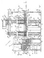
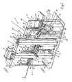
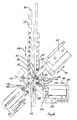
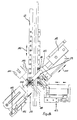
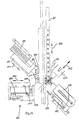
- Figures 1 to 3 is the overall structure of a line feed device 4 shown with line changer.
- line changer viewed from above - V-shaped and to each other mirror image of one between the two feeders lying vertical mirror plane 21 (Fig. 4, 5) compiled.
- the two line feed devices are expedient assembled with a line changer on a horizontal base plate 1, which is preferably trapezoidal, the a line feed device with line changer in the area 2 one side edge and the other in area 3 of the other Side edge of the base plate 1 is arranged. Is shown in 1 to 3 of these only the line feed device constructed in area 2 4th
- the line feeder with line changer 4 which in following, for the sake of simplicity, only with feed device 4 is referred to, points in the line transport direction 5 from behind (line inlet side) lined up to the front (line outlet side) a line straightening station 6, a line transport station 7 and a line withdrawal station 8.
- FIGS. 1 to 3 Lines 9, leading line paths 9a, one above the other vertically and horizontally parallel at a distance from each other through the Feeder 4 are performed. Of course you can more line paths 9a may be provided.
- the feeder shown 4 is for twelve superimposed line paths designed. In combination with the other not shown Feeder can thus twenty-four lines 9 are kept ready in line paths 9a.
- All lines 9 are from storage facilities, not shown deducted and on the straightening station side or in the transport direction inserted into the feed device 4 from behind and into Transport direction 5 horizontally through the entire feed device 4 performed.
- At the retraction end of the feeder 4 are each from a mouth of a nozzle 10 Lines 9 can be removed, the nozzles 10 also at a distance the lines 9 are arranged vertically one above the other.
- the nozzles 10 downstream of the transport direction 5 is the first processing station a line processing machine provided (not shown).
- the transport station 7 is stored with a storage slide system in each case 20 on the three next to each other transversely to the transport direction 5 standing support columns 12. It is designed such that they on line paths 9a of both feeders 4 in height a transport path 9c in which a selected line 9 to Line processing machine is transported, can act. Therefore, one line path can be seen in FIGS. 4 and 5 11, the feed device 4 and shown in FIGS. 1 to 3 the other line path 13 is arranged in mirror image other feed device, not shown, the conduction paths 11, 13 because of the V-shaped arrangement of the two Feeders also from the rear (line inlet side) run towards the front (line outlet side) in a V-shape.
- the transport station 7 consists essentially of a means of transport for two lines 9 with a conveyor system 21a drivable belts or conveyor belts endlessly guided around pulleys, the belt conveyor system 21a horizontal, the means with vertically aligned roller axes and upright standing belt is arranged.
- the belt conveyor system 21a has one between the in each a vertical line path level 129 lying line paths 11, 13 internally toothed conveyor belt or conveyor belt 14 on whose transport strand is actively working on the transportation of a line with some play between the tapered conduction paths 11, 13 sit and thus also run conically.
- the transport belt 14 wraps around the line outlet (in hereinafter referred to only on the outlet side) a drivable Gear 15 runs to the line inlet side (in the following only with inlet side or inlet side) with parallel to the line paths 11, 13 extending lateral Transport runs 14a, 14b to deflection rollers 17 and from there V-shaped to an inlet-side counter-bearing roller 18, which the Strap also wraps around.
- Between the gear 15 and the Deflection rollers 17 run the transport runs 14a, 14b between the support rollers 16 arranged on the strands 14a, 14b.
- the driving straps 19, 22 have the same structure and are mirror images arranged to each other. They each loop around the drive gear 15 laterally adjacent drivable drive gear 23 and each run with a conveyor belt side Transport strand 24, 25 and an outside return strand 26, 27 to a deflection roller 28, the deflection rollers 28 to the deflection rollers 17 are arranged laterally adjacent.
- the transport strands 24, 25 are guided over support rollers 29.
- the conveyor belt system stored on the central column 12 with the conveyor belt 14, the gear 15, the support rollers 16, the deflection rollers 17 and the counter-roller 18 is as a unit on a slide plate or a slide 30 of the Bearing slide system 20 mounted.
- the shift plate 30 is through a parallel displacement horizontally perpendicular to the Line paths 11, 13 (double arrow direction 31) can be moved guided stored so that the transport runs 14a, 14b vertically to a line path 11, 13 in a horizontal plane can be moved.
- This is used as a detail in FIG. 2
- a recognizable sliding gate system supported on the support column 12 32, which is shown schematically as detail B in FIG. 4 and 5 is shown.
- the link slide system 32 has a sliding block plate arranged on the sliding plate 30 33 with an angled to lying in the mirror plane 21 Sliding axis 34 extending slot 35, the one from a fixed part of the sliding plate 30 slidably supporting Bearing plate system 20 arranged bolt 36 is penetrated.
- the sliding block plate 33 is on the inlet side of a slide rod 36 arranged with e.g. a pneumatically operated one Piston-cylinder unit 37 communicates.
- the two are on one side Support column consisting of 12 driving belt systems from the driving belts 19 and 22, the drive gears 23, the guide rollers 28 and the support rollers 29 with one each the slide system 20 slidably mounted slide plate or a sliding carriage 40 is arranged.
- the sliding plates 40 are each with a e.g. pneumatically operated, piston cylinder unit supported on the bearing plate system 20 41, each with a push rod 42 with the Sliding plate 40 is connected, in the double arrow direction 43 slidably such that the conveyor belts or conveyor belts 19, 22 with their transport strands 24, 25 horizontally perpendicular to the respective line path 11, 13 are displaceable.
- the Transport station 7 are therefore the transport runs 14a, 14b, 24, 25 arranged parallel to the line paths 11, 13.
- the drive gears 23 are during the operation of the feed device 4 continuously driven so that the transport strands 24, 25 keep running.
- the direction of rotation of the continuously running drive gear 15 changes or reverses each during the shift from a line path 11 to the other line path 13 such that each of the transport runs or conveyor run 14a, 14b of the conveyor belt 14 with the Transport runs or conveyor runs 24, 25 of the driving belts 19, 22 run in the same direction and at the same speed.
- the drives are in accordance with this synchronization coupled, with telescopic drive shafts 44, insert their parts into each other in a rotationally fixed manner, underneath the drive gearwheels 15, 23 are connected to the drive gears and to a gear system arranged on the base plate 1 51 run (Fig. 6, 7).
- the drive shafts 44 enable each due to an upper universal joint 45 and a lower universal joint 46 and the telescopic displaceability an angle the drive shafts 44 when moving the belt systems in arrow directions 48, 49, 50 or 52, 53, 54 in particular also during the drive, that is, with rotating shafts 44th
- the transmission of the transmission system 51 is located on the middle one Drive shaft 44 of the conveyor belt system fixedly arranged Gear 55 and a toothed belt 56 with a not shown Engine connected.
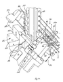
- FIG. 4 and 5 illustrate the changing conveyance of the funding or transport station 7.
- Fig. 4 it is shown that the Transport strand 14b of the conveyor belt system together with the Transport strand 24 of a drive belt system line 9 the conduction path 11 jams and promotes when the transport system is driven.
- Fig. 5 it is shown that the Transport belt system moved parallel to line path 13 is offset to the axis 34 and the transport strand 25 of the other Driving belt system the transport run 14a of the transport belt system is switched on, so that a line 9 of the line path 13 can be funded.
- the lines 9 are, as already described, in a vertical Level 129 at a distance above one another in line paths 9a or 11 and 13 held in the feed device 4.
- the two-part Mounted up and down mounted bracket consists of one in the transport direction 5 extending first inlet side Frame 57 and a second outlet-side frame 58, the transport station being between the two frames 57, 58 7 is located.
- the frame 57 points from the inlet side to the outlet side in succession a vertical first spar 59, one on top of it End attached, horizontally extending traverse 60, one downwardly arranged second upper traverse 62 and a second vertical, arranged at the end of the second cross member 62 Holm 63 up.
- a vertical intermediate beam 64 is provided on the cross member 60 and below the step edge 65 on the traverse set down 62 attached another vertical spar 66.
- the spars 66 and 63 are at their lower ends above a lower horizontal Truss 67 in a fixed connection, so that the trusses 65 and 67 with the spars 66 and 63 a first square frame 68 form, whose lower traverse 67 is approximately at the level of the bearing plate system 22 is located.
- the frame 58 downstream of the transport station 7 has another square frame 69, which is about the same size dimensioned and arranged at the same height as the frame 68.
- the further frame 69 consists of the upper horizontal Traverse 70, the lower horizontal traverse 71 and the two vertical side rails 72, 73. Stand approximately in their longitudinal center the trusses 70, 71 with a vertical intermediate spar 74 in Connection.
- the lower traverse 71 projects a bit beyond the attachment point of the vertical side member 73 and is telescopically supported a truss arm 75a, at its free outlet end a vertically upwardly extending nozzle bar 76 is arranged is.
- the connection between the truss arm 75a and the Nozzle strip 76 takes place by means of a joint, preferably one Ball joint, at least with a joint that is vertical Hinge axis.
- the spars 59, 64, 61, 63, 72, 73 and the nozzle bar 76 are for line paths 9a, 11, 13, respectively, aligned holes 77 provided so that the lines 9 in each of the feeders be stored horizontally.
- the ends of so-called Spring strands 78 which are tubular and made of Windings consist of helically wound wires.
- the spring strings are both flexible and stretchy. Instead of the spring strands 78, tubular strands can also be made another elastically bendable and stretchable material used become.
- the spring strands 78 stuck in the spar 72 are continuous to the nozzle bar 76 and are in the spars 74 and 73 and fixedly arranged in the nozzle bar 76 (FIGS. 8, 9). You can move a bit towards the transport station on the inlet side 7 protrude from the spar 72.
- the meaning and purpose of the elastic Tubes 78 will be discussed below.
- the trusses 62, 67 and the trusses 70, 71 are with guides 79 guided up and down on vertical rails 80.
- the rails 80 sit on vertically standing, in the area of Side edges 2 of the base plate 1 arranged columns 81.
- Die Columns 81 are at their head end with a cross member 82 in Connection that continues on the outlet side and above the Nozzle bar 76 ends.
- the traverse 82 carries in the free end region a bearing arm extending transversely to the transport direction 5 83, on which also extends transversely to the transport direction 5 upper slide 84 on guides 85 across movably supported (double arrow direction 84a).
- the base plate 1 also transversely to Transport direction 5 extending bearing bar 86 arranged, the a lower carriage 87 on guides 88 traversable outsourced.
- the slides 84, 87 are in a vertical zone arranged one below the other and standing above two vertical ones Rails 89, from which only that of the feeder 4 shown is because the other feeder is not shown together in connection.
- the other track of the second Feed device 4, not shown, extends parallel at a distance from the illustrated rail 89 and stored in the illustrated recess 90 of the carriage 84, 87. With this device, the rails 89 in the double arrow direction 84a are moved so that each nozzle 10 in front of the processing station 124 can be driven.
- this Drive means e.g. a piston cylinder assembly.
- the arm 75 is articulated on the bar 76 and elastically bendable and extensible spring strands 78 are used, the movability of the rails 98 is ensured.
- the pillars 81 each carry a bearing block in the free end region 94, 95.
- the bearing blocks 94, 95 are rotatably supported one to the other bracket horizontally and parallel to the direction of transport 5 extending shaft 96.
- the shaft 96 passes through the bearing blocks 94, 95 each one piece, on the outlet side protruding end of a drive gear 97 followed by a drive transmission gear 98 and on the inlet side protruding end of a driving gear 99 are attached.
- the foot area of the columns 81 is vertically below the columns each drive gear 97, 99 a deflection gear 100, 101 rotatable stored.
- a finite toothed belt 103 is guided over the toothed wheels 97, 101.
- the upper end of the toothed belt 102 is at 104 on the crossbar 62 and the lower end of this toothed belt is at 105 on the Traverse 67 attached.
- the drive gear 98 from an endless belt 93 wrapped around, which led upwards a gear 92 Drive device of a motor mounted on the traverse 82 91 wraps around.
- the drive device or the motor 91 rotates the shaft 96 and Depending on the direction of rotation, it raises or lowers vertically and synchronously the two frame frames 57, 58 with the lines stored therein 9 in the double arrow direction 116 and positioned in each case a predetermined line 9 between the conveyor belts fixed transport station 7.
- the transport device 7 is then used to transport the positioned line switched on and promotes a line section of this line the nozzle 10 of the nozzle bar 76.
- a the conveyed pipe section Corresponding line section is made at the same time the supply device on the inlet side into the feed device 4 drawn.
- the gripper 111 if it has a ring or gripping projection 114 of the clamping device 109 has gripped and pulled will, unclamp the line 9. After opening of the gripper 111 can the clamping device 109 under its own Return the spring force to line 9 and clamp the latter again.
- the meaning and purpose of the clamping device is explained below explained.
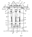
- the line withdrawal station 8 is located each outside of this room and outside of the respective line paths 9a and 11, 13 in the area between the two spars 74, 73 (Fig. 8, 9). In the spars 74, 73 are the Spring strands 78 clamped. Station 8 has a vertical one Bearing ledge 120, which is attached to the cross members 70, 71.
- the push bar 123 stands with the piston of a piston-cylinder unit 118 in Connection, which is supported on the bar 120 (not shown).
- the cylinder section 122 expediently has one Height that allows multiple conduction paths 9a, 11, 13 or To capture spring strands 78.
- the mouths of the nozzles 10 of the Line paths 9a and 11, 13 are in a vertical, plane extending transversely to the transport direction 5 (FIG. 8, 9).
- a knife device 124 of a not shown Processing device of a line processing machine their inlet-side limitation in the level of the mouths of the Nozzles 10 is. Since the knife of the knife device 124 Distance from the inlet-side boundary are arranged, remains after cutting a line 9 with the knives short line protrusion 9b that emerges from the mouth of the nozzle 10 protrudes. This projection 9b interferes with the vertical movement the frame frames 57, 58; the cable ends can be crushed or be bent so that they are uncontrolled during the later advance against equipment of the line processing machine encounter, which leads to accidents. For this reason, the Line changes, i.e.
- the line retraction station works for how follows (see Fig. 8, 9). If a line 9 is to be changed, the clamping devices 109 are expedient, at least in the spar 72 also activated in the spar 63 and the lines 9 clamped.
- the sheet forming device 121 is in the direction of Line paths 9a or 11, 13 advanced.
- the cylinder wall of the cylinder section presses arches directed towards the interior 117 in the spring strand areas 78a of the spring strands 78, which are located between the spars 74, 73 and clamped in the latter are. Bend and stretch the spring strand sections 78a becomes elastic, so that section 78a is extended.
- a line withdrawal station thus works a line deflection method with which a line from its straight axial orientation is deflected, being in Transport direction is clamped before the deflection, so that the line end arranged in the transport direction after the recess in the direction of deflection or against the transport direction is withdrawn.
- This can be the shape of the deflection be arbitrary.
- the return of the line end can be done by Elimination of the deflection when using the effect of self-elastic Leadership forces take place. But you can also by The deflection device acts by the deflection device the line from the deflection back to the starting position leads back or presses.
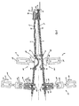
- the transport station 7 is a line straightening station on the inlet side 6 upstream, which as usual consists of two straightening roller sets 6a, 6b.
- Each straightening roller set 6a, 6b has an upper one and a lower roller conveyor 127, 128, each in the transport direction throat rolls arranged one behind the other as straightening rolls 125 on.
- the straightening rollers 125 are rotatable on perpendicular to Transport direction 5 arranged roller axes 126, the Axes 126 of the lower roller conveyor 128 to the axes 126 of the Upper roller conveyor 127 one path length in the transport direction "a" are arranged offset from one another (FIG. 14).
- the fillets of the rollers 125 of the roller conveyors that are driven against one another 127, 128 form a conduit in transport direction 5, through which a line 9 fits.
- the channel diameter is set to the diameter of the line 9 or to the line type, which should be processed.
- the straightening roller sets 6a, 6b are identical.
- the lower roller conveyor 128 of the straightening roller set 6a is stored in the roller-side free upper end area of a carriage 130 (Fig. 14), with the axes 126 of the rollers 125 in the transport direction 5 sit in side-by-side bearing blocks 131 and the bearing blocks 131 in the free end region in each case in one Run out guide web 132, which is beveled on the roller side towards the roller are so that an insertion funnel 133 for a line 9th is formed.
- the guide webs 132 engage between the Bearing blocks 131 provided gaps 132a.
- the rollers 125 are stuck in the transport direction 5 extending slots 134 of the Bearing blocks 131, their groove in the insertion funnel 133 empties.
- the carriage 130 is on a guide system 135 in the double arrow direction 136 on a slope to the vertical plane 129 slidably mounted and by means of a not shown Drive, e.g. one supported on the guide system 135, pneumatically operated piston-cylinder unit in the double arrow direction 136 procedure.
- the guidance system 135 is on one Bearing plate 137 attached, which in turn on one on the Base plate 1 arranged storage frame 138 rests (Fig. 3).
- the upper roller conveyor 127 of the straightening roller set 6b is supported like that lower roller conveyor 128 of the straightening roller set 6a in the roller side free lower end region of a carriage 139, wherein this free end area is designed in the same way as for the carriage 130.
- the carriage 139 is on a guide system 140 in the double arrow direction 141 on a slope mounted to the vertical plane 129 and also with a drive means, not shown, e.g. one on Guide system 140 supporting pneumatically operated piston-cylinder unit Move in double arrow direction 141.
- the guidance system 140 rests on one arranged on the base plate 1 Storage rack 142.
- the upper roller conveyor 127 of the straightening roller set 6a is on the roller side free end area of a carriage 143 in a Facility that resembles the one in the top Roller conveyor 127 of the straightening roller set 6b or in the lower one Roller conveyor 128 of straightening roller set 6a is seated.
- the carriage 143 is on a guide system 144 in the double arrow direction 145 slidable on a slope to the vertical plane 129 stored and by means of a drive, not shown, e.g. one pneumatically supported on the guide system 144 Working piston cylinder unit move, the carriage 143 against one arranged in the guide system 144, preferably fixed, but possibly also adjustable stop encounters.
- the guide system 144 is supported on a storage rack 147, which is arranged on the base plate 1.
- the lower roller conveyor 128 of the straightening roller set 6b is also supported the same means as the upper roller conveyor 127 of the straightening roller set 6a in the free roller-side end region of a carriage 148 on a guide system 149 in the double arrow direction 150 displaceable on a slope to the vertical plane 129 stored and by means of a drive, e.g. one on the management system 149 supporting pneumatic piston-cylinder unit 151 against one arranged in the guide system 149 Stop can be moved.
- the guidance system 149 supports itself on a storage rack 152 seated on the base plate 1 from.
- the straightening station 6 operates according to the invention automatically by changing the diameter of the conduit automatically is set.
- those are already described Fixed stops in the guide systems the carriage 143 and 148 provided.
- a stop system is provided which for each line has a stop.
- a stop device 153 according to the invention is on the side the vertical plane 129, on which the carriage 130, 139 are positioned between the carriages. she has one on the facing part of the storage racks 138, 142 supporting guide system 154 in which a stop slide 155 horizontally in the direction of the vertical plane 129 in Double arrow direction 156 slidably supports.
- the sledge 155 has a stop head at its vertical plane end 157 on. With a piston cylinder unit 158, the is supported on the guide system 154, the stop slide Movable in the double arrow direction 156.
- a stop screw is located in the free end area of each strip 159, 160 161, 162 rotatably screwed in, the stop head the screw 161 diagonally downwards and the stop head of the Screw 162 points obliquely upwards.
- the stop head 161 of the Stop bar 159 protrudes into the path of movement of the carriage 130, the one with a stop element or a stop edge is provided, which can abut the stop head 161.
- equally the stop head 162 of the stop bar 160 protrudes the path of movement of the carriage 139, which also with is provided with a stop element against which the stop head 162 can come across.
- the stop head 157 of the stop slide acts 155 with counter stop heads 163 one vertically on the spar 64 fixed counter stop bar 165 together.
- the counter stop heads 163 sit firmly on horizontally aligned pins 164, which carry a thread and in a corresponding Thread arranged perpendicular to the vertical plane 129 in the Counter stop bar 165 are screwed. It determines the Screw-in depth the width with which the counter stop head 163 protrudes from the counter stop bar 165. 11 is recognizable that the counter-stop heads 163 of different distances protrude from the strip 165.
- the heads 163 are at a height arranged, which corresponds to the height of a line path 9a, so that a head 163 each assigned to a line 9 is.
- the position of the heads 163 becomes the thickness or the type or the like of the assigned line selected in advance, so that during the operation of the line feed device 4 no further adjustment is required. Because the counter stop bar 165 is firmly attached to the vertical spar 64 proceed with this in double arrow direction 116.
- the carriage 155 For changing a line, the carriage 155 is removed from the Bar 165 moved away and all the slides of the straightening station 6 moved apart. By tilting the Travel carriage is created a space in which the Lines and the strip 165 with the heads 163 freely in the double arrow direction 116 are movable. After positioning one carriage 155 moves against the new line in its travel located head 163 and thus determines the location of the Stop heads of screws 161, 162. Then the Traversing slides move towards each other, with the traversing slides 130 and 139 against the heads of the stop screws 161, 162 butt, which determines the diameter of the duct becomes.
Landscapes
- Engineering & Computer Science (AREA)
- Manufacturing & Machinery (AREA)
- Structure Of Belt Conveyors (AREA)
- Tyre Moulding (AREA)
- Manufacture Of Motors, Generators (AREA)
Claims (49)
- Dispositif d'amenée de lignes avec changeur de lignes pour machines de traitement de lignes, présentant au moinscaractérisé en ce queune station de dressage (6)une station de transport (7)une station de retrait de lignes (8),a) plusieurs chemins de lignes (9a) horizontaux pour des lignes (9) s'étendant d'un côté entrée de lignes au côté sortie de lignes, en passant par le dispositif d'amenée de lignes (4), sont disposés les uns au-dessus des autres avec un écart dans le sens vertical et parallèlement les uns aux autres, et se terminent chacun côté sortie dans une buse de sortie (10),b) les chemins de ligne (9a) sont logés dans un bâti (57, 58) mobile verticalement vers le haut et vers le bas,c) la station de transport (7) est disposée en s'insérant dans un vide du bâti, à hauteur d'un chemin de transport (9c) d'une ligne (9),d) la station de retrait de lignes (8) est disposée en aval de la station de transport (7), dans la direction du transport (5), et présente un dispositif de déviation de lignes (121) qui provoque, par déviation de la ligne (9) se trouvant dans le chemin de transport (9c) et à remplacer, au moins, le retrait de la ligne concernée (9) dans la buse (10).
- Dispositif d'amenée de lignes selon la revendication 1,
caractérisé en ce que le dispositif de déviation de lignes (121) est conçu de façon à pouvoir dévier et retirer dans les buses plusieurs lignes (9) simultanément. - Dispositif d'amenée de lignes selon la revendication 1 et/ou 2,
caractérisé en ce que le dispositif de déviation de lignes (121) est un dispositif formant une courbe qui présente un tronçon cylindrique (122) orienté verticalement faisant saillie en forme de courbe en direction du chemin de ligne (11 à 13), qui est relié à une unité cylindre-piston (118) appuyée sur le châssis, de façon qu'il puisse être amené contre le chemin de ligne (11 à 13) et ramené. - Dispositif d'amenée de lignes selon une ou plusieurs des revendications 1 à 3,
caractérisé en ce que le chemin de ligne, dans la zone de la station de retrait de lignes, est un tube (78) réalisé dans un matériau élastiquement flexible et extensible, en particulier une barre élastique et le dispositif de déviation (121) agit sur un tronçon (78a) du tube (78), le tronçon de tube (78a) étant fixé de part et d'autre, de sorte qu'il est élastiquement cintré et allongé lors de la déviation. - Dispositif d'amenée de lignes selon la revendication 4,
caractérisé en ce que la ligne (9) guidée dans le tube (78) peut être coincée côté entrée du tronçon de tube (78a) avec un dispositif de serrage. - Dispositif d'amenée de lignes selon une ou plusieurs des revendications 1 à 5,
caractérisé en ce que la station de transport de lignes (7) est disposée de manière fixe à la hauteur du chemin de transport (9c) et est conçue de manière à agir sur les chemins de transport (9c) de deux dispositifs d'amenée (4) disposés l'un à côté de l'autre, dirigés l'un vers l'autre en forme de V. - Dispositif d'amenée de lignes selon la revendication 6,
caractérisé en ce que la station de transport (7) est essentiellement constituée d'un moyen de transport pour une ligne (9) avec un système à courroie de transport (21a) comportant des courroies pouvant être entraínées guidées sans fin autour de poulies de renvoi, le système de transport à courroie (21a) étant disposé horizontalement avec des axes de poulies orientés verticalement et des courroies se trouvant de chant. - Dispositif d'amenée de lignes selon la revendication 6 et/ou 7,
caractérisé en ce que le système de transport à courroie (21a) présente une courroie de transport (14) dentée à l'intérieur agencée entre les chemins de ligne (11, 13), dont les brins de transport (14a, 14b) fonctionnant de manière active lors du transport d'une ligne sont situés avec un faible jeu entre les chemins de ligne (11, 13) orientés en cône des deux dispositifs d'amenée de lignes (4) et sont orientés également en cône, la courroie de transport (14) passant, côté sortie de ligne, sur une roue dentée pouvant être entraínée (15), se dirigeant en direction du côté entrée de ligne avec des brins de transport latéraux (14a, 14b) qui s'étendent parallèlement aux chemins de ligne (11, 13) vers des poulies de renvoi (17) et de là, en formant un V, vers un galet de butée (18) côté entrée, autour duquel la courroie (14) passe également. - Dispositif d'amenée de lignes selon la revendication 8,
caractérisé en ce que les brins de transport (14a, 14b), entre la roue dentée (15) et les poulies de renvoi (17), passent sur des galets supports (16) disposés entre les brins. - Dispositif d'amenée de lignes selon une ou plusieurs des revendications 6 à 9,
caractérisé en ce qu'une courroie d'entraínement (19,22) pouvant être entraínée, montée de manière mobile horizontalement, perpendiculairement au chemin de ligne (11) à (13), est disposée à côté de la courroie de transport (14), de part et d'autre de celle-ci. - Dispositif d'amenée de lignes selon la revendication 10,
caractérisé en ce que les courroies d'entraínement (19, 22) sont conçues de manière identique et sont disposées symétriquement l'une par rapport à l'autre. - Dispositif d'amenée de lignes selon la revendication 10 et/ou 11,
caractérisé en ce que les courroies d'entraínement (19, 22) passent chacune sur une roue dentée motrice (23) pouvant être entraínée, située latéralement à côté de la roue dentée motrice (15) et chacune avec un brin de transport côté courroie de transport (24, 25) et un brin de retour côté extérieur (26, 27) va vers une poulie de renvoi (28), ladite poulie de renvoi (28) étant disposée à côté des poulies de renvoi (17) latéralement. - Dispositif d'amenée de lignes selon la revendication 12,
caractérisé en ce que les brins de transport (24, 25) sont guidés par l'intermédiaire de galets supports (29). - Dispositif d'amenée de lignes selon une ou plusieurs des revendications 6 à 13,
caractérisé en ce que le système à courroies de transport comprenant la courroie de transport (14), la roue dentée (15), les galets supports (16), les poulies de renvoi (17) et le galet de butée (18) est monté comme un ensemble sur un chariot mobile (30), lequel est monté guidé de façon à coulisser dans la direction horizontale, perpendiculairement aux chemins de ligne (11, 13). - Dispositif d'amenée de lignes selon la revendication 14,
caractérisé en ce qu'il est prévu, pour déplacer le chariot (30), un système de curseur coulissant (31) qui présente une plaque (33) disposée sur le chariot (30), munie d'un trou oblong (35) orienté avec un angle par rapport à l'axe de déplacement (34) situé dans le plan du niveau (21) et traversé par un goujon (36) s'appuyant sur une pièce fixée sur le châssis, la plaque du curseur coulissant étant agencée côté entrée sur une tige de curseur (36) qui est en liaison avec une unité cylindre-piston (37) appuyée sur le bâti. - Dispositif d'amenée de lignes selon une ou plusieurs des revendications 6 à 15,
caractérisé en ce que chaque système à courroie d'entraínement comprenant la courroie d'entraínement (19 à 22), la roue dentée motrice (23), la poulie de renvoi (28) et les galets supports (29) est disposée sur un chariot mobile (40) pouvant se déplacer avec une unité cylindre-piston (41) qui s'appuie sur le bâti de la machine de façon que les courroies de transport avec leurs brins de transport (24, 25) puissent se déplacer dans une direction horizontale perpendiculairement au chemin de ligne (11, 13) correspondant. - Dispositif d'amenée de lignes selon une ou plusieurs des revendications 6 à 16,
caractérisé en ce que les roues dentées motrices (23) sont entraínées de manière ininterrompue pendant le fonctionnement du dispositif d'amenée (4), de sorte que les brins de transport (24, 25) tournent en continu et que le sens de rotation de la roue dentée motrice (15) change, le sens de rotation des roues dentées motrices (23) changeant en sens contraire. - Dispositif d'amenée de lignes selon une ou plusieurs des revendications 6 à 17,
caractérisé en ce que des arbres de commande télescopiques (44), dont les pièces s'imbriquent les unes dans les autres de manière fixe en rotation, sont en liaison avec les roues dentées motrices (15, 23), au-dessous de celles-ci, et sont dirigés vers un système de réducteur (51) disposé sur une plaque de base (1), les arbres de commande (44) présentant chacun une articulation à cardan supérieure (45) et une articulation à cardan inférieure (46). - Dispositif d'amenée de lignes selon la revendication 18,
caractérisé en ce que le réducteur du système de réducteur (51) est en liaison avec un moteur par l'intermédiaire d'une courroie dentée (56). - Dispositif d'amenée de lignes selon une ou plusieurs des revendications 1 à 19,
caractérisé en ce que les chemins de ligne (9a) sont disposés dans un plan vertical (129) dans un support en deux parties, et en ce que le support présente un premier bâti (57) côté entrée s'étendant dans le sens du transport (5) et un deuxième bâti côté sortie (58), la station de transport (7) se trouvant entre les deux bâtis (57, 58). - Dispositif d'amenée de lignes selon la revendication 20,
caractérisé en ce que le bâti (57) présente successivement, du côté entrée vers le côté sortie, un premier montant vertical (59), une traverse (60) s'étendant horizontalement, fixée à l'extrémité supérieure dudit montant, une deuxième traverse supérieure (62) disposée en étages vers le bas, ainsi qu'un deuxième montant vertical (63) disposé à l'extrémité de la deuxième traverse (60), un montant intermédiaire vertical (64) qui se trouve sur la traverse (60), au-dessous du milieu de sa longueur (60), et un autre montant vertical (66) est fixé sur la traverse (62) étagée vers le bas et les montants (66 et 63) sont reliés de façon fixe à leurs extrémités inférieures par l'intermédiaire d'une traverse horizontale inférieure (67), de sorte que la traverse (65 et 67) avec les montants (66 et 63) forment un premier cadre rectangulaire (68), dont la traverse inférieure (67) se trouve à peu près à hauteur du chemin de transport (9c). - Dispositif d'amenée de lignes selon la revendication 20 et/ou 21,
caractérisé en ce que le bâti (58) présente un autre cadre rectangulaire (69) de dimensions à peu près identiques et disposé à la même hauteur que le cadre (68), constitué de la traverse horizontale supérieure (67) et de la traverse horizontale inférieure (61) et des deux montants latéraux verticaux (72, 73), un autre montant intermédiaire (74) étant disposé à peu près au milieu de la longueur des traverses (70, 71) et en ce que la traverse inférieure (71) dépasse un peu du point de montage du montant latéral vertical (73) et loge un bras de traverse (75a) télescopique à l'extrémité libre duquel est disposée, côté sortie, une barrette de buses (76), la liaison entre le bras de traverse (75a) et la barrette de buses (76) s'effectuant au moyen d'une articulation. - Dispositif d'amenée de lignes selon une ou plusieurs des revendications 1 à 22,
caractérisé en ce que des trous alignés (77) sont prévus dans les montants (59, 64, 61, 63, 72, 73) et la barrette de buses (76) pour les chemins de ligne (9a), de manière que les lignes (9) soient logées horizontalement dans chacun des dispositifs d'amenée (4). - Dispositif d'amenée de lignes selon une ou plusieurs des revendications 1 à 23,
caractérisé en ce que les extrémités de barres élastiques (78), de forme tubulaire et constituées d'enroulements de fils enroulés en forme de ressort à boudin, sont insérées dans les trous (77) des montants (61 et 63), ainsi que dans les montants (72, 74, 73) et la barrette à buses (76), formant les chemins de lignes. - Dispositif d'amenée de lignes selon une ou plusieurs des revendications 1 à 24,
caractérisé en ce que les barres élastiques (78) insérées dans le montant (72) sont traversantes jusqu'à la barrette à buses (76) et sont disposées de façon fixe dans les montants (74 et 73) ainsi que dans la barrette à buses (76). - Dispositif d'amenée de lignes selon une ou plusieurs des revendications 1 à 25,
caractérisé en ce que les traverses (62, 67), ainsi que les traverses (70, 71), sont guidées avec des guides (79) sur des rails verticaux (80) de manière à pouvoir descendre et monter. - Dispositif d'amenée de lignes selon la revendication 26,
caractérisé en ce que les rails (80) sont disposés sur des colonnes verticales (81) qui sont en liaison à leur extrémité supérieure avec une traverse (82) qui se poursuit du côté sortie et se termine au-dessus de la barrette à buses (76), la traverse (82) portant, dans la zone d'extrémité libre, un bras de palier (83) s'étendant dans le sens transversal à la direction de transport (5), sur lequel un chariot de déplacement (84) supérieur qui s'étend également transversalement à la direction de transport (5), est logé mobile transversalement sur des guides (85) et en ce que, au-dessous du bras de palier (83), sur la plaque de base (1), est disposée une poutre d'appui (86) s'étendant également dans le sens transversal à la direction de transport (5), qui loge de manière mobile dans le sens transversal un chariot de déplacement inférieur (87) sur des guides (88), les chariots (84, 87) étant disposés l'un au-dessous de l'autre dans une zone verticale et étant en liaison l'un avec l'autre par l'intermédiaire de deux rails verticaux (89), sur lesquels les barrettes à buses (76) sont logées mobiles vers le haut et vers le bas. - Dispositif d'amenée de lignes selon la revendication 26 et/ou 27,
caractérisé en ce que, dans la zone d'extrémité libre, les colonnes (81) portent chacune un support de palier (94, 95), lesdits supports de paliers logeant, de manière à pouvoir tourner, un arbre (96) s'étendant d'un support de palier à l'autre dans une direction horizontale et parallèle à la direction de transport (5), en ce que l'arbre (96) traverse en partie les supports de paliers (94, 95) et une roue dentée d'entraínement (97), suivie par une roue dentée de report de l'entraínement (98), sont fixées à l'extrémité dépassant du côté sortie et une roue dentée d'entraínement (59) est fixée à l'extrémité dépassant du côté entrée, une roue dentée de renvoi (100, 101) étant montée dans la zone inférieure des colonnes (81) de manière mobile en rotation sur les colonnes verticalement au-dessous de chaque roue dentée d'entraínement (97, 99). - Dispositif d'amenée de lignes selon la revendication 28,
caractérisé en ce qu'une courroie dentée à bout libre (102) est guidée par l'intermédiaire des roues dentées (99, 100) et une courroie dentée à bout libre (103) est guidée par l'intermédiaire des roues dentées (97, 101), l'extrémité supérieure de la courroie dentée (102) étant fixée sur la traverse (62) et l'extrémité inférieure de la courroie dentée (103) se trouve sur la traverse (70) et l'extrémité inférieure de la courroie dentée (103) se trouve sur la traverse (71). - Dispositif d'amenée de lignes selon la revendication 29,
caractérisé en ce qu'une courroie sans fin (93) passe sur la roue dentée motrice (98), est guidée vers le haut et passe sur une roue dentée (92) du dispositif de commande d'un moteur (91) reposant sur la traverse (82). - Dispositif d'amenée de lignes selon une ou plusieurs des revendications 1 à 30,
caractérisé en ce que des dispositifs de serrage (109) des lignes (9) sont disposés sur les montants (63 et 72). - Dispositif d'amenée de lignes selon la revendication 31,
caractérisé en ce qu'il est prévu, pour le dispositif de serrage (109), un orifice de serrage (108) qui débouche perpendiculairement dans un trou de passage de ligne (77), un verrou de blocage (109a) chargé par ressort qui se trouve dans l'orifice de serrage (108) et agit contre un contre-palier (109b), le verrou de blocage traversant un évidement prévu à cet effet dans la barre élastique (78) jusqu'au chemin de ligne (9a) et pouvant serrer une ligne (9). - Dispositif d'amenée de lignes selon la revendication 32,
caractérisé en ce qu'un dispositif de traction (110) fixé sur le bâti est monté en amont des dispositifs de serrage (109), à hauteur du chemin de transport (9c), et présente une pince (111) qui peut saisir le dispositif de serrage (109), la pince (111) étant en liaison avec une unité piston-cylindre (112) qui l'active. - Dispositif d'amenée de lignes selon une ou plusieurs des revendications 1 à 33,
caractérisé en ce qu'une station de dressage de lignes (6) montée en amont de la station de transport (7) côté entrée est constituée de deux jeux de rouleaux de dressage (6a, 6b), qui présentent chacun une voie de rouleaux supérieure et inférieure (127, 128), les voies de rouleaux étant disposées mobiles sur une inclinaison par rapport au plan vertical (129) dans lequel les chemins de ligne (9a) sont disposés. - Dispositif d'amenée de lignes selon la revendication 34,
caractérisé en ce que les voies de rouleaux (127, 128) sont équipées de rouleaux à gorge comme rouleaux de dressage (125) disposés les uns derrière les autres dans le sens de transport et en ce que les rouleaux de dressage (125) sont montés mobiles en rotation sur des axes de rouleaux (126) disposés perpendiculairement à la direction de transport (5), les axes (126) de la voie de rouleaux inférieure (128) étant disposés décalés d'une longueur de course (a) dans le sens du transport par rapport aux axes (126) de la voie de rouleaux supérieure (127). - Dispositif d'amenée de lignes selon la revendication 34 et/ou 35,
caractérisé en ce que les axes (126) des rouleaux de dressage (125) sont disposés avec un angle β de 45° de préférence par rapport au plan vertical (129), tous les axes (126) d'un jeu de rouleaux de dressage (6a à 6b) étant parallèles les uns aux autres et les axes (126) du jeu de rouleaux de dressage (6a) étant orientés perpendiculairement aux axes (126) du jeu de rouleaux de dressage (6b). - Dispositif d'amenée de lignes selon une ou plusieurs des revendications 34 à 36,
caractérisé en ce que les jeux de rouleaux de dressage (61, 6b) sont réalisés de manière identique. - Dispositif d'amenée de lignes selon une ou plusieurs des revendications 34 à 37,
caractérisé en ce que la voie de rouleaux inférieure (128) du jeu de rouleaux de dressage (6a) est située dans la zone d'extrémité supérieure libre côté rouleaux d'un chariot mobile (130), les axes (126) des rouleaux (125) dans la direction de transport (5) étant montés dans des supports de paliers (131) disposés les uns à côté des autres, qui se terminent chacun dans la zone d'extrémité libre par une aile de guidage (132) qui est biseautée côté rouleau en direction du rouleau, de façon à former un entonnoir d'introduction (133) pour une ligne (9). - Dispositif d'amenée de lignes selon la revendication 38,
caractérisé en ce que les ailes de guidage (132) s'insèrent dans des creux (132a) prévus entre les supports de palier (131), et les rouleaux sont enfoncés dans des fentes (134) des supports de paliers (131) s'étendant dans la direction du transport (5), leur gorge débouchant dans l'entonnoir d'introduction (133). - Dispositif d'amenée de lignes selon la revendication 38 et/ou 39,
caractérisé en ce que le chariot mobile (130) est monté de manière à coulisser sur un système de guidage (135) sur une partie inclinée par rapport au plan vertical (129) et est mobile au moyen d'un entraínement non représenté, le système de guidage (135) étant fixé sur une plaque de palier (137) qui repose, à son tour, sur un châssis de palier (138) agencé sur la plaque de base (1). - Dispositif d'amenée de lignes selon une ou plusieurs des revendications 34 à 40,
caractérisé en ce que la voie de rouleaux supérieure (127) du jeu de rouleaux de dressage (6b) est logée dans la zone d'extrémité libre inférieure côté rouleaux d'un chariot mobile (139), la zone d'extrémité libre étant formée de la même manière que pour le chariot mobile (130) et en ce que le chariot mobile (139) est monté de façon à coulisser avec un moyen d'entraínement sur un système de guidage (140) sur une partie inclinée par rapport au plan vertical (129), le système de guidage étant situé sur un châssis (142) disposé sur la plaque de base (1). - Dispositif d'amenée de lignes selon une ou plusieurs des revendications 34 à 41,
caractérisé en ce que la voie de rouleaux supérieure (127) du jeu de rouleaux (6a) est logée dans la zone d'extrémité libre côté rouleaux d'un chariot mobile (143) dans un dispositif qui est identique à celui dans lequel se trouve la voie de rouleaux supérieure (127) du jeu de rouleaux de dressage (6b), respectivement dans lequel se trouve la voie de rouleaux inférieure (128) du jeu de rouleaux de dressage (6a), le chariot mobile (143) étant monté de façon à coulisser sur un système de guidage (144) sur une partie inclinée par rapport au plan vertical (129) et pouvant se déplacer au moyen d'un moyen d'entraínement s'appuyant sur le système de guidage (144), le chariot (143) pouvant reposer contre une butée réglable disposée dans le système de guidage (144) et en ce que le système de guidage (144) est logé sur un châssis de palier (147) qui est disposé sur la plaque de base (1). - Dispositif d'amenée de lignes selon une ou plusieurs des revendications 34 à 42,
caractérisé en ce que la voie de rouleaux inférieure (128) du jeu de rouleaux de dressage (6b) est logée avec les mêmes moyens que ceux de la voie de rouleaux supérieure (127) du jeu de rouleaux de dressage (6a) dans la zone d'extrémité libre côté rouleaux d'un chariot mobile (148) qui est logé sur un système de guidage (149) sur une partie inclinée par rapport au plan vertical (129) et peut se déplacer au moyen d'un entraínement s'appuyant sur le système de guidage (149) contre une butée disposée dans le système de guidage (149) et en ce que le système de guidage (149) s'appuie sur un châssis de palier (152) situé sur la plaque de base (1). - Dispositif d'amenée de lignes selon une ou plusieurs des revendications 34 à 43,
caractérisé en ce qu'un système de butée, qui présente une butée pour chaque ligne, est aménagé pour les chariots mobiles (130 et 139). - Dispositif d'amenée de lignes selon la revendication 44,
caractérisé en ce que le système de butée présente un dispositif de butée (153) qui est disposé du côté du plan vertical (129) duquel se trouvent les chariots mobiles (130, 139), le dispositif de butée étant positionné entre les chariots mobiles. - Dispositif d'amenée de lignes selon la revendication 45,
caractérisé en ce que le dispositif de butée (153) présente un système de guidage (154) s'appuyant sur la partie en regard des châssis de palier (138, 142), dans laquelle un chariot de butée (155) est logé mobile horizontalement dans la direction du plan vertical (129), le chariot de butée (155) présentant à son extrémité côté plan vertical une tête de butée (157) et pouvant se déplacer avec une unité cylindre-piston (158) qui s'appuie sur le système de guidage (154). - Dispositif d'amenée de lignes selon la revendication 46,
caractérisé en ce que, de part et d'autre de la tête de butée (157), une nervure de contre-butée (159, 160) s'étendant horizontalement à partir de la tête et parallèlement à la direction de transport (5) est placée à la tête, la nervure (159) étant avantageusement orientée par rapport à la nervure (160) en tournant de 90° à la manière d'un vantail autour d'un axe longitudinal horizontal et en ce que les nervures (159, 160) portent des éléments de butée pour les chariots (130, 139). - Dispositif d'amenée de lignes selon la revendication 47,
caractérisé en ce que dans la zone d'extrémité libre de chaque nervure (159, 160) une vis de butée (161, 162) est vissée de manière à pouvoir tourner, la tête de butée de la vis (161) regardant à l'oblique vers le bas et la tête de butée de la vis (162) regardant à l'oblique vers le haut et les têtes de butée pénétrant dans le trajet de déplacement du chariot mobile (130 à 139) et coopérant avec un élément de butée disposé sur ce chariot. - Dispositif d'amenée de lignes selon une ou plusieurs des revendications 44 à 48,
caractérisé en ce que la tête de butée (147) coopère avec des têtes de contre-butée (163) d'une nervure de contre-butée (165) disposée fixe verticalement sur le montant (64), les têtes de contre-butée (163) étant vissées dans des filetages disposés dans la nervure de contre-butée, (165) perpendiculairement au plan vertical (129).
Applications Claiming Priority (2)
| Application Number | Priority Date | Filing Date | Title |
|---|---|---|---|
| DE19749114A DE19749114A1 (de) | 1997-11-06 | 1997-11-06 | Leitungszuführeinrichtung mit Leistungswechsler für Leistungsverarbeitungsmaschinen |
| DE19749114 | 1997-11-06 |
Publications (3)
| Publication Number | Publication Date |
|---|---|
| EP0915539A2 EP0915539A2 (fr) | 1999-05-12 |
| EP0915539A3 EP0915539A3 (fr) | 2000-05-24 |
| EP0915539B1 true EP0915539B1 (fr) | 2002-09-18 |
Family
ID=7847854
Family Applications (1)
| Application Number | Title | Priority Date | Filing Date |
|---|---|---|---|
| EP98120129A Expired - Lifetime EP0915539B1 (fr) | 1997-11-06 | 1998-10-26 | Un dispositif d'amenée des conducteurs ayant un dispositif de changement pour un machine de traitement des conducteurs |
Country Status (2)
| Country | Link |
|---|---|
| EP (1) | EP0915539B1 (fr) |
| DE (2) | DE19749114A1 (fr) |
Families Citing this family (3)
| Publication number | Priority date | Publication date | Assignee | Title |
|---|---|---|---|---|
| JP6010131B2 (ja) * | 2011-11-11 | 2016-10-19 | シュロニガー ホールディング アーゲー | 線材輸送装置 |
| CN109246578B (zh) * | 2018-10-16 | 2023-09-05 | 南京闻新声学科技有限公司 | 扬声器磁体剥离装配机 |
| CN114901576B (zh) * | 2020-01-13 | 2025-11-28 | 施洛伊尼格股份公司 | 导线进料装置 |
Family Cites Families (3)
| Publication number | Priority date | Publication date | Assignee | Title |
|---|---|---|---|---|
| WO1982000423A1 (fr) * | 1980-07-31 | 1982-02-18 | Petrov P | Dispositif de bobinage pour articles de forme allongee |
| US4493233A (en) * | 1983-06-22 | 1985-01-15 | Artos Engineering Company | Apparatus for cutting and conveying segments of wire or cable |
| EP0496049B1 (fr) * | 1991-01-21 | 1995-05-17 | Ttc Technology Trading Company | Perfectionnement au dispositif pour l'alimentation d'un câble dans un automate pour façonner des câbles |
-
1997
- 1997-11-06 DE DE19749114A patent/DE19749114A1/de not_active Withdrawn
-
1998
- 1998-10-26 DE DE59805596T patent/DE59805596D1/de not_active Expired - Fee Related
- 1998-10-26 EP EP98120129A patent/EP0915539B1/fr not_active Expired - Lifetime
Also Published As
| Publication number | Publication date |
|---|---|
| EP0915539A3 (fr) | 2000-05-24 |
| EP0915539A2 (fr) | 1999-05-12 |
| DE59805596D1 (de) | 2002-10-24 |
| DE19749114A1 (de) | 1999-05-12 |
Similar Documents
| Publication | Publication Date | Title |
|---|---|---|
| DE69002243T2 (de) | Stromabwärts einer Biegeeinrichtung angeordnete Ziehvorrichtung und Verfahren zum Biegen der hinteren Enden von Stangen. | |
| DE3903270C2 (de) | Vorrichtung zum lagerichtigen Aufschieben mehrerer Wickelhülsen auf spreizbare Wellen | |
| WO1991004113A1 (fr) | Dispositif de pliage de barres en acier afin de façonner des elements d'armatures en beton | |
| EP0623542A1 (fr) | Dispositif pour empiler un chant de feuilles imprimées | |
| EP0552144B1 (fr) | Dispositif d'amenee et de remplacement d'une pluralite de cables | |
| EP1079478A1 (fr) | Procédé et dispositif pour couper et/ou dénuder des fils isolés | |
| AT401360B (de) | Biegeanlage für stäbe | |
| DE2723846A1 (de) | Biegemaschine fuer draht | |
| CH684374A5 (de) | Kabelzuführungs- und -wechseleinrichtung für eine Kabelverarbeitungsmaschine. | |
| DE3727339A1 (de) | Vorrichtung zum wechseln von auf eine vorratsrolle aufgewickelten folienbahnen | |
| EP2774735A1 (fr) | Station et procédé de traitement pour l'application d'un élément profilé | |
| DE4040167C2 (de) | Anlage zum kontinuierlichen Schneiden von Kunststoffblöcken | |
| EP3331792B1 (fr) | Dispositif de remplissage d'un pot de filature avec un ruban de fibres | |
| DE1635182A1 (de) | Klammer-Vorrichtung fuer biaxiale Gewebestreckmaschine | |
| EP0915538B1 (fr) | Dispositif d'alignement, notamment pour un dispositif d'amenée des conducteurs ayant un dispositif de changement pour un machine de traitement des conducteurs | |
| DE4323820C2 (de) | Vorrichtung zum Herstellen von Abstandhalterrahmen für Isolierglasscheiben aus Hohlprofilleisten | |
| EP0915539B1 (fr) | Un dispositif d'amenée des conducteurs ayant un dispositif de changement pour un machine de traitement des conducteurs | |
| DE69414644T2 (de) | Vorrichtung zur Herstellung von Bauelementen | |
| DE69805446T2 (de) | Ladevorrichtung einer werkzeugmaschine mit zuarbeitungs-stangen | |
| AT393641B (de) | Vorrichtung zum biegen von stahlstaeben zu betonbewehrungselementen | |
| AT394959B (de) | Schneidanlage zum abschneiden von stuecken waehlbarer laenge von einem gitterrost | |
| EP3126071B1 (fr) | Dispositif d'avance et de dressage | |
| AT394324B (de) | Verfahren und anlage zum entzundern von rundstahlstaeben | |
| DE2431790A1 (de) | Verfahren und vorrichtung zum kehlnahtschweissen der laengsglieder von rahmenkonstruktionen | |
| DE2408158A1 (de) | Vorrichtung zum gleichzeitigen absondern und umsetzen von gegenstaenden |
Legal Events
| Date | Code | Title | Description |
|---|---|---|---|
| PUAI | Public reference made under article 153(3) epc to a published international application that has entered the european phase |
Free format text: ORIGINAL CODE: 0009012 |
|
| AK | Designated contracting states |
Kind code of ref document: A2 Designated state(s): CH DE FR GB IT LI |
|
| AX | Request for extension of the european patent |
Free format text: AL;LT;LV;MK;RO;SI |
|
| PUAL | Search report despatched |
Free format text: ORIGINAL CODE: 0009013 |
|
| AK | Designated contracting states |
Kind code of ref document: A3 Designated state(s): AT BE CH CY DE DK ES FI FR GB GR IE IT LI LU MC NL PT SE |
|
| AX | Request for extension of the european patent |
Free format text: AL;LT;LV;MK;RO;SI |
|
| 17P | Request for examination filed |
Effective date: 20001018 |
|
| AKX | Designation fees paid |
Free format text: CH DE FR GB IT LI |
|
| GRAG | Despatch of communication of intention to grant |
Free format text: ORIGINAL CODE: EPIDOS AGRA |
|
| 17Q | First examination report despatched |
Effective date: 20020129 |
|
| GRAG | Despatch of communication of intention to grant |
Free format text: ORIGINAL CODE: EPIDOS AGRA |
|
| GRAH | Despatch of communication of intention to grant a patent |
Free format text: ORIGINAL CODE: EPIDOS IGRA |
|
| GRAH | Despatch of communication of intention to grant a patent |
Free format text: ORIGINAL CODE: EPIDOS IGRA |
|
| GRAA | (expected) grant |
Free format text: ORIGINAL CODE: 0009210 |
|
| AK | Designated contracting states |
Kind code of ref document: B1 Designated state(s): CH DE FR GB IT LI |
|
| REG | Reference to a national code |
Ref country code: GB Ref legal event code: FG4D Free format text: NOT ENGLISH |
|
| REG | Reference to a national code |
Ref country code: CH Ref legal event code: EP |
|
| REG | Reference to a national code |
Ref country code: CH Ref legal event code: NV Representative=s name: BRAUN & PARTNER PATENT-, MARKEN-, RECHTSANWAELTE |
|
| REF | Corresponds to: |
Ref document number: 59805596 Country of ref document: DE Date of ref document: 20021024 |
|
| GBT | Gb: translation of ep patent filed (gb section 77(6)(a)/1977) |
Effective date: 20021212 |
|
| ET | Fr: translation filed | ||
| PLBE | No opposition filed within time limit |
Free format text: ORIGINAL CODE: 0009261 |
|
| STAA | Information on the status of an ep patent application or granted ep patent |
Free format text: STATUS: NO OPPOSITION FILED WITHIN TIME LIMIT |
|
| 26N | No opposition filed |
Effective date: 20030619 |
|
| PGFP | Annual fee paid to national office [announced via postgrant information from national office to epo] |
Ref country code: GB Payment date: 20041027 Year of fee payment: 7 |
|
| PGFP | Annual fee paid to national office [announced via postgrant information from national office to epo] |
Ref country code: FR Payment date: 20041029 Year of fee payment: 7 |
|
| PGFP | Annual fee paid to national office [announced via postgrant information from national office to epo] |
Ref country code: CH Payment date: 20051024 Year of fee payment: 8 |
|
| PGFP | Annual fee paid to national office [announced via postgrant information from national office to epo] |
Ref country code: DE Payment date: 20051025 Year of fee payment: 8 |
|
| PG25 | Lapsed in a contracting state [announced via postgrant information from national office to epo] |
Ref country code: IT Free format text: LAPSE BECAUSE OF NON-PAYMENT OF DUE FEES;WARNING: LAPSES OF ITALIAN PATENTS WITH EFFECTIVE DATE BEFORE 2007 MAY HAVE OCCURRED AT ANY TIME BEFORE 2007. THE CORRECT EFFECTIVE DATE MAY BE DIFFERENT FROM THE ONE RECORDED. Effective date: 20051026 Ref country code: GB Free format text: LAPSE BECAUSE OF NON-PAYMENT OF DUE FEES Effective date: 20051026 |
|
| GBPC | Gb: european patent ceased through non-payment of renewal fee |
Effective date: 20051026 |
|
| PG25 | Lapsed in a contracting state [announced via postgrant information from national office to epo] |
Ref country code: FR Free format text: LAPSE BECAUSE OF NON-PAYMENT OF DUE FEES Effective date: 20060630 |
|
| REG | Reference to a national code |
Ref country code: FR Ref legal event code: ST Effective date: 20060630 |
|
| PG25 | Lapsed in a contracting state [announced via postgrant information from national office to epo] |
Ref country code: LI Free format text: LAPSE BECAUSE OF NON-PAYMENT OF DUE FEES Effective date: 20061031 Ref country code: CH Free format text: LAPSE BECAUSE OF NON-PAYMENT OF DUE FEES Effective date: 20061031 |
|
| PG25 | Lapsed in a contracting state [announced via postgrant information from national office to epo] |
Ref country code: DE Free format text: LAPSE BECAUSE OF NON-PAYMENT OF DUE FEES Effective date: 20070501 |
|
| REG | Reference to a national code |
Ref country code: CH Ref legal event code: PL |