EP0915544A1 - Appareil électrique, en particulier dérivateur de surtensions, muni d'un dispositif indiquant un courant de défaut - Google Patents
Appareil électrique, en particulier dérivateur de surtensions, muni d'un dispositif indiquant un courant de défaut Download PDFInfo
- Publication number
- EP0915544A1 EP0915544A1 EP98811058A EP98811058A EP0915544A1 EP 0915544 A1 EP0915544 A1 EP 0915544A1 EP 98811058 A EP98811058 A EP 98811058A EP 98811058 A EP98811058 A EP 98811058A EP 0915544 A1 EP0915544 A1 EP 0915544A1
- Authority
- EP
- European Patent Office
- Prior art keywords
- housing
- electrical apparatus
- thermocolor
- information carrier
- fault current
- Prior art date
- Legal status (The legal status is an assumption and is not a legal conclusion. Google has not performed a legal analysis and makes no representation as to the accuracy of the status listed.)
- Granted
Links
- 239000000463 material Substances 0.000 claims abstract description 4
- 230000003287 optical effect Effects 0.000 claims abstract description 4
- 230000001965 increasing effect Effects 0.000 claims abstract 2
- 239000012212 insulator Substances 0.000 claims description 6
- 239000011810 insulating material Substances 0.000 claims description 3
- 230000000694 effects Effects 0.000 abstract description 2
- 238000010438 heat treatment Methods 0.000 abstract 1
- 230000001012 protector Effects 0.000 abstract 1
- 239000004020 conductor Substances 0.000 description 5
- 238000004804 winding Methods 0.000 description 3
- 238000001514 detection method Methods 0.000 description 2
- 239000002360 explosive Substances 0.000 description 2
- 229920001296 polysiloxane Polymers 0.000 description 2
- 229910052573 porcelain Inorganic materials 0.000 description 2
- 239000004593 Epoxy Substances 0.000 description 1
- 230000001680 brushing effect Effects 0.000 description 1
- 239000000969 carrier Substances 0.000 description 1
- 230000002950 deficient Effects 0.000 description 1
- 239000000945 filler Substances 0.000 description 1
- 238000004519 manufacturing process Methods 0.000 description 1
- 229910044991 metal oxide Inorganic materials 0.000 description 1
- 150000004706 metal oxides Chemical class 0.000 description 1
- 238000012544 monitoring process Methods 0.000 description 1
- 239000002245 particle Substances 0.000 description 1
- 229920000642 polymer Polymers 0.000 description 1
- 239000002994 raw material Substances 0.000 description 1
- 230000011664 signaling Effects 0.000 description 1
- 238000005507 spraying Methods 0.000 description 1
- 230000000007 visual effect Effects 0.000 description 1
Images
Classifications
-
- H—ELECTRICITY
- H01—ELECTRIC ELEMENTS
- H01T—SPARK GAPS; OVERVOLTAGE ARRESTERS USING SPARK GAPS; SPARKING PLUGS; CORONA DEVICES; GENERATING IONS TO BE INTRODUCED INTO NON-ENCLOSED GASES
- H01T1/00—Details of spark gaps
- H01T1/12—Means structurally associated with spark gap for recording operation thereof
Definitions
- the invention is based on an electrical apparatus, in particular a surge arrester, according to the generic term of Claim 1.
- the invention takes on a state of the art of electrical apparatus Reference as specified in EP 0 564 334 A1.
- One in this state of the art Electrical apparatus described which is preferably used as a surge arrester or is designed as an insulator for high or medium voltage networks, contains one of the monitoring of the electrical apparatus for a fault current serving detection and display device. This device has one Isolierstoffgeophuse with an easily breakable window.
- the insulating housing is a power connection of the electrical apparatus guided.
- the part of the power connection inside the housing is from surround a magnetic core, which the secondary winding of the Bears current connection as a primary winding current transformer.
- the Secondary winding is connected to an ohmic resistor, which is in an im Explosive charge arranged inside the housing is embedded.
- the object of the invention is as set out in the claims based on specifying an electrical apparatus of the type mentioned at which the faulty condition of the electrical apparatus with extremely simple Medium and can still be recognized with great certainty.
- a fault current Incorrect operating state caused by an information carrier indicated which at least part of the outer surface of an insulating material housing of the apparatus contains.
- This information carrier is provided by the Fault current heated to a limit temperature that is above the permissible Operating temperature of the device is. When the limit temperature is exceeded this information carrier gives an easy and safe to detect optical Signal off. Since such an information carrier is advantageously a Insulated housing contains provided thermal color (Thermocolor), can be can produce and can such apparatus in a simple and inexpensive manner existing equipment without much effort by applying the Thermocolors can be retrofitted to the housing.
- Thermal color Thermocolor
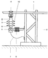
- the single figure shows a phase conductor of a high-voltage line, which with a surge arrester and a device to display fault currents containing electrical apparatus according to the Invention is electrically connected.
- reference numeral 1 denotes a phase conductor on one grounded mast 2 electrically insulated high voltage line.
- a surge arrester 3 is suspended.
- the surge arrester 3 is galvanic with a current connection 4 with the phase conductor 1 connected and is attached to the mast 2 by means of a post insulator 6.
- a second Power connection 5 of the surge arrester 3 is connected via a grounding cable 7 the mast 2 galvanically connected.
- a high-voltage insulated housing 8 encloses a, not shown, between the power connections 4, 5 arranged stacks of non-linear resistance elements on the base of metal oxides and carries a device designed as an information carrier 9 for the visual display of a faulty one caused by a fault current State of the surge arrester.
- the housing 8 is advantageously made of a porcelain or a filler-filled polymer, such as one in particular Silicone and / or an epoxy, and preferably has porcelain or silicone existing screens 10 on.
- the information carrier 9 is on part of the outer surface of the insulating material housing 8 provided. This part of the outer surface of the insulating housing 8 is when a fault current carried in the resistance stack occurs to a Temperature heated, which is above an allowable operating temperature of the Apparatus. When a temperature above the permissible operating temperature is exceeded (e.g. 105 ° C) limit temperature of typically 150 up to 500 ° C, the information carrier 9 emits an optically detectable signal.
- the information carrier 9 is advantageously on one of the temperature-increasing Effect of the fault current exposed and good from the outside recognizable part of the outer surface of the housing 8, in particular below or arranged above one of the screens 10.
- the information carrier 9 preferably contains a thermocolor, for example [Co (NH 3 ) 6 ] ⁇ PO 4 , which is applied to the outer surface or at least part of the outer surface of the housing 9.
- This thermocolor changes its color above the limit temperature, [Co (NH 3 ) 6 ] ⁇ PO 4, for example at 200 ° C. from yellow to blue, and retains this color even after the temperature has dropped below the limit temperature.
- the color change permanently indicates that the surge arrester 3, which can be identified by the color change, is defective.
- thermocolor can be used in the production of the housing-forming material material-forming raw materials are mixed.
- the housing 8 formed then also represents the information carrier 9
- Thermocolor can be used to retrofit an existing appliance but also in the form of a ribbon or a strip to form one heat-transferring contact surface at least on part of the outer surface of the Housing 8 are applied. This can be done in a particularly simple manner Thermocolor by spraying or brushing at least part of the Be applied to the outer surface of the housing 9.
- the information carrier 9 In order to be able to recognize the information carrier 9 particularly well in the dark , it is advisable to make them luminous and / or reflective. In this can be achieved in a particularly advantageous manner by admixing a fluorescent color or reflective particles can be reached to the Thermocolor.
- the information carrier can also be attached to one other electrical apparatus, for example an isolator of a switch or a transformer, or an insulator of a high-voltage system, for example, the post insulator 6.
- one other electrical apparatus for example an isolator of a switch or a transformer, or an insulator of a high-voltage system, for example, the post insulator 6.
Landscapes
- Thermistors And Varistors (AREA)
- Testing Electric Properties And Detecting Electric Faults (AREA)
- Gas-Insulated Switchgears (AREA)
Applications Claiming Priority (2)
| Application Number | Priority Date | Filing Date | Title |
|---|---|---|---|
| DE19749522A DE19749522A1 (de) | 1997-11-08 | 1997-11-08 | Elektrischer Apparat, insbesondere Überspannungsableiter, mit einer Vorrichtung zur Anzeige eines Fehlerstromstroms |
| DE19749522 | 1997-11-08 |
Publications (2)
| Publication Number | Publication Date |
|---|---|
| EP0915544A1 true EP0915544A1 (fr) | 1999-05-12 |
| EP0915544B1 EP0915544B1 (fr) | 2003-12-03 |
Family
ID=7848106
Family Applications (1)
| Application Number | Title | Priority Date | Filing Date |
|---|---|---|---|
| EP98811058A Expired - Lifetime EP0915544B1 (fr) | 1997-11-08 | 1998-10-22 | Dérivateur de surtensions, muni d'un dispositif indiquant un courant de défaut |
Country Status (3)
| Country | Link |
|---|---|
| US (1) | US6028759A (fr) |
| EP (1) | EP0915544B1 (fr) |
| DE (2) | DE19749522A1 (fr) |
Cited By (2)
| Publication number | Priority date | Publication date | Assignee | Title |
|---|---|---|---|---|
| WO2007117163A1 (fr) * | 2006-04-12 | 2007-10-18 | Abb Sp. Z O.O. | Parafoudre basse tension comprenant un indicateur visuel d'anomalie |
| CN105762650A (zh) * | 2016-04-19 | 2016-07-13 | 国家电网公司 | 带雷击放电计数装置的防雷内置柱式限压器 |
Families Citing this family (3)
| Publication number | Priority date | Publication date | Assignee | Title |
|---|---|---|---|---|
| CZ29574U1 (cs) * | 2016-05-03 | 2016-06-21 | Saltek S.R.O. | Přepěťová ochrana se signalizací překročení provozní teploty |
| WO2017191566A1 (fr) * | 2016-05-03 | 2017-11-09 | Saltek S.R.O. | Protection de surtension avec indication de température de fonctionnement dépassée |
| CA178834S (en) | 2017-08-01 | 2019-02-28 | The Trustees For The Time Being Of The Live Line Int Trust | Drop out electrical surge arrestor |
Citations (6)
| Publication number | Priority date | Publication date | Assignee | Title |
|---|---|---|---|---|
| GB798918A (en) * | 1956-08-22 | 1958-07-30 | Siemens Ag | Improvements in or relating to electric surge arresters |
| JPH0256884A (ja) * | 1988-08-22 | 1990-02-26 | Ngk Insulators Ltd | 避雷碍子装置における動作表示装置 |
| JPH05190252A (ja) * | 1992-01-17 | 1993-07-30 | Nichiyu Giken Kogyo Kk | アーク発生検知具 |
| EP0564334A1 (fr) * | 1992-03-30 | 1993-10-06 | Sediver, Societe Europeenne D'isolateurs En Verre Et Composite | Dispositif pour la détection et la signalisation d'un courant de défaut dans un parafoudre ou un isolateur |
| JPH0870522A (ja) * | 1994-08-29 | 1996-03-12 | Yazaki Corp | 素子作動確認用窓を備えた電気接続箱 |
| EP0729209A1 (fr) * | 1995-02-23 | 1996-08-28 | ABB Management AG | Dispositif d'indication d'un état défectueux d'un appareil électrique, en particulier un dérivateur de surtensions |
Family Cites Families (3)
| Publication number | Priority date | Publication date | Assignee | Title |
|---|---|---|---|---|
| GB9005827D0 (en) * | 1990-03-15 | 1990-05-09 | Raychem Gmbh | Electrical protection apparatus |
| US5237482A (en) * | 1991-07-10 | 1993-08-17 | Joslyn Corporation | High voltage surge arrester with failed surge arrester signaling device |
| US5341271A (en) * | 1992-06-22 | 1994-08-23 | Minnesota Mining And Manufacturing Company | Surge arrester fault indicator |
-
1997
- 1997-11-08 DE DE19749522A patent/DE19749522A1/de not_active Withdrawn
-
1998
- 1998-10-22 DE DE59810327T patent/DE59810327D1/de not_active Expired - Fee Related
- 1998-10-22 EP EP98811058A patent/EP0915544B1/fr not_active Expired - Lifetime
- 1998-11-06 US US09/186,887 patent/US6028759A/en not_active Expired - Fee Related
Patent Citations (6)
| Publication number | Priority date | Publication date | Assignee | Title |
|---|---|---|---|---|
| GB798918A (en) * | 1956-08-22 | 1958-07-30 | Siemens Ag | Improvements in or relating to electric surge arresters |
| JPH0256884A (ja) * | 1988-08-22 | 1990-02-26 | Ngk Insulators Ltd | 避雷碍子装置における動作表示装置 |
| JPH05190252A (ja) * | 1992-01-17 | 1993-07-30 | Nichiyu Giken Kogyo Kk | アーク発生検知具 |
| EP0564334A1 (fr) * | 1992-03-30 | 1993-10-06 | Sediver, Societe Europeenne D'isolateurs En Verre Et Composite | Dispositif pour la détection et la signalisation d'un courant de défaut dans un parafoudre ou un isolateur |
| JPH0870522A (ja) * | 1994-08-29 | 1996-03-12 | Yazaki Corp | 素子作動確認用窓を備えた電気接続箱 |
| EP0729209A1 (fr) * | 1995-02-23 | 1996-08-28 | ABB Management AG | Dispositif d'indication d'un état défectueux d'un appareil électrique, en particulier un dérivateur de surtensions |
Non-Patent Citations (3)
| Title |
|---|
| PATENT ABSTRACTS OF JAPAN vol. 014, no. 225 (E - 0927) 14 May 1990 (1990-05-14) * |
| PATENT ABSTRACTS OF JAPAN vol. 017, no. 608 (E - 1457) 9 November 1993 (1993-11-09) * |
| PATENT ABSTRACTS OF JAPAN vol. 096, no. 007 31 July 1996 (1996-07-31) * |
Cited By (3)
| Publication number | Priority date | Publication date | Assignee | Title |
|---|---|---|---|---|
| WO2007117163A1 (fr) * | 2006-04-12 | 2007-10-18 | Abb Sp. Z O.O. | Parafoudre basse tension comprenant un indicateur visuel d'anomalie |
| CN105762650A (zh) * | 2016-04-19 | 2016-07-13 | 国家电网公司 | 带雷击放电计数装置的防雷内置柱式限压器 |
| CN105762650B (zh) * | 2016-04-19 | 2018-03-09 | 国家电网公司 | 带雷击放电计数装置的防雷内置柱式限压器 |
Also Published As
| Publication number | Publication date |
|---|---|
| EP0915544B1 (fr) | 2003-12-03 |
| US6028759A (en) | 2000-02-22 |
| DE59810327D1 (de) | 2004-01-15 |
| DE19749522A1 (de) | 1999-05-12 |
Similar Documents
| Publication | Publication Date | Title |
|---|---|---|
| EP0016351B1 (fr) | Détecteur de gaz à utiliser dans un milieu menacé par des explosions | |
| DE2740695A1 (de) | Funkenstreckenabsicherung | |
| CH631296A5 (de) | Fehlersichere ueberspannungsschutzvorrichtung. | |
| EP0729209B1 (fr) | Dispositif d'indication d'un état défectueux d'un appareil électrique, en particulier un dérivateur de surtensions | |
| DE19717802A1 (de) | Funkenstrecke | |
| EP0387865B1 (fr) | Dispositif de protection contre des étincelles pour conducteurs isolés, en particulier pour lignes aériennes | |
| DE69300752T2 (de) | Nachweis- und Signalisierungsvorrichtung eines Fehlerstroms in einem Überspannungsableiter oder einem Isolator. | |
| DE69121702T2 (de) | Elektrische vorrichtung | |
| EP0915544A1 (fr) | Appareil électrique, en particulier dérivateur de surtensions, muni d'un dispositif indiquant un courant de défaut | |
| DE69511397T2 (de) | Vorrichtung zur anzeige eines fehlerhaften überspannungsableiters | |
| DE2928727C2 (de) | Kabelendverschluß für Mittelspannungs- und Hochspannungskabel | |
| DE4220259C2 (de) | Schutzanordnung zum Schutz elektrischer Einrichtungen gegen Überspannungen auf dem Stromversorgungsnetz | |
| EP1052665A2 (fr) | Court-circuiteur | |
| DE3631177A1 (de) | Vorrichtung zum schutz gegen ueberspannungen bei elektrogeraeten | |
| EP0915345A2 (fr) | Appareil électrique, en particulier un limiteur de surtension , pourvu d'un affichage de courants de fuite | |
| DE3829650A1 (de) | Kombinierte loeschfunkenstrecke | |
| EP0927445B1 (fr) | Appareil electrique, notamment dispositif de protection contre les surtensions, et systeme d'affichage de l'etat de cet appareil dans un dispositif d'evaluation central | |
| DE8025215U1 (de) | Niederspannungs-Ventilableiter | |
| DE3688777T2 (de) | Korrosionsschutzeinrichtung an der Kappe eines elektrischen Hängeisolators. | |
| US7256978B2 (en) | Gapped ground safety device | |
| EP0678961A1 (fr) | Circuit reconnaissant et affichant l'interruption d'un conducteur | |
| DE19626275A1 (de) | Niederspannungsableiter | |
| AT399601B (de) | Stromwandler für einen hochspannungsleiter | |
| DE1565284B2 (de) | Anordnung zur feststellung von fehlern in der induktions spule kernloser induktionsoefen waermeoefen u dgl | |
| DE3514686A1 (de) | Vorrichtung zur meldung eines kohlebuerstenverschleisses |
Legal Events
| Date | Code | Title | Description |
|---|---|---|---|
| PUAI | Public reference made under article 153(3) epc to a published international application that has entered the european phase |
Free format text: ORIGINAL CODE: 0009012 |
|
| AK | Designated contracting states |
Kind code of ref document: A1 Designated state(s): DE FR GB IT SE |
|
| AX | Request for extension of the european patent |
Free format text: AL;LT;LV;MK;RO;SI |
|
| 17P | Request for examination filed |
Effective date: 19990614 |
|
| AKX | Designation fees paid |
Free format text: DE FR GB IT SE |
|
| RAP1 | Party data changed (applicant data changed or rights of an application transferred) |
Owner name: ABB HOCHSPANNUNGSTECHNIK AG |
|
| RAP1 | Party data changed (applicant data changed or rights of an application transferred) |
Owner name: ABB SCHWEIZ AG |
|
| 17Q | First examination report despatched |
Effective date: 20020917 |
|
| RTI1 | Title (correction) |
Free format text: SURGE ARRESTER WITH A FAULT CURRENT INDICATING DEVICE |
|
| GRAH | Despatch of communication of intention to grant a patent |
Free format text: ORIGINAL CODE: EPIDOS IGRA |
|
| GRAS | Grant fee paid |
Free format text: ORIGINAL CODE: EPIDOSNIGR3 |
|
| GRAA | (expected) grant |
Free format text: ORIGINAL CODE: 0009210 |
|
| AK | Designated contracting states |
Kind code of ref document: B1 Designated state(s): DE FR GB IT SE |
|
| PG25 | Lapsed in a contracting state [announced via postgrant information from national office to epo] |
Ref country code: IT Free format text: LAPSE BECAUSE OF FAILURE TO SUBMIT A TRANSLATION OF THE DESCRIPTION OR TO PAY THE FEE WITHIN THE PRE;WARNING: LAPSES OF ITALIAN PATENTS WITH EFFECTIVE DATE BEFORE 2007 MAY HAVE OCCURRED AT ANY TIME BEFORE 2007. THE CORRECT EFFECTIVE DATE MAY BE DIFFERENT FROM THE ONE RECORDED.SCRIBED TIME-LIMIT Effective date: 20031203 Ref country code: FR Free format text: LAPSE BECAUSE OF FAILURE TO SUBMIT A TRANSLATION OF THE DESCRIPTION OR TO PAY THE FEE WITHIN THE PRESCRIBED TIME-LIMIT Effective date: 20031203 |
|
| REG | Reference to a national code |
Ref country code: GB Ref legal event code: FG4D Free format text: NOT ENGLISH |
|
| REF | Corresponds to: |
Ref document number: 59810327 Country of ref document: DE Date of ref document: 20040115 Kind code of ref document: P |
|
| PG25 | Lapsed in a contracting state [announced via postgrant information from national office to epo] |
Ref country code: SE Free format text: LAPSE BECAUSE OF FAILURE TO SUBMIT A TRANSLATION OF THE DESCRIPTION OR TO PAY THE FEE WITHIN THE PRESCRIBED TIME-LIMIT Effective date: 20040303 |
|
| GBT | Gb: translation of ep patent filed (gb section 77(6)(a)/1977) |
Effective date: 20040213 |
|
| PGFP | Annual fee paid to national office [announced via postgrant information from national office to epo] |
Ref country code: DE Payment date: 20041008 Year of fee payment: 7 |
|
| PLBE | No opposition filed within time limit |
Free format text: ORIGINAL CODE: 0009261 |
|
| STAA | Information on the status of an ep patent application or granted ep patent |
Free format text: STATUS: NO OPPOSITION FILED WITHIN TIME LIMIT |
|
| PGFP | Annual fee paid to national office [announced via postgrant information from national office to epo] |
Ref country code: GB Payment date: 20041011 Year of fee payment: 7 |
|
| 26N | No opposition filed |
Effective date: 20040906 |
|
| EN | Fr: translation not filed | ||
| PG25 | Lapsed in a contracting state [announced via postgrant information from national office to epo] |
Ref country code: GB Free format text: LAPSE BECAUSE OF NON-PAYMENT OF DUE FEES Effective date: 20051022 |
|
| PG25 | Lapsed in a contracting state [announced via postgrant information from national office to epo] |
Ref country code: DE Free format text: LAPSE BECAUSE OF NON-PAYMENT OF DUE FEES Effective date: 20060503 |
|
| GBPC | Gb: european patent ceased through non-payment of renewal fee |
Effective date: 20051022 |